
1
Instructions for useASA 3000
Active Antenna Splitter 2 x 1:8

2
Contents
Safety information ......................................................... 3
Delivery includes ............................................................. 3
Operating elements ........................................................ 4
Connection diagram ....................................................... 5
Trouble shooting ............................................................. 9
Accessories .................................................................... 10
Specifications ................................................................ 11
Manufacturer declarations ......................................... 12
Brief description
With the 2 x 1:8 active antenna splitter, up to eight recei-
vers (EM 3031) or twin receivers (EM 3032, EM 3532) can
be operated with only one pair of diversity antennas.
Each diversity section is fitted with a wideband input
module which can be exchanged for a selective input
module. Due to the built-in antenna boosters, the signals
are routed without loss the the connected receivers.
The active antenna splitter allows you to make receiver
systems with up to 16 channels.
Areas of application:
Multi-channel RF installations (fixed or mobile)
Permanent installations in small conference centres and
similar venues

3
Safety information
The 2 x 1:8 active antenna splitter must only be set up and
connected by an electrical engineering expert.
Never open electronic units! This must only be done by
authorized personnel and is all the more important for
units connected to AC outlets. If units are opened by custo-
mers in breach of this instruction, the warranty becomes
null and void!
Make sure that the air vents of the unit are not covered or
blocked. Keep the unit away from central heating radiators
and electric heaters!
Set up the unit on an even surface or mount it into a rack!
Lay the cables in such a way that no-one can stumble over
them!
Keep liquids and small parts which conduct electricity away
from the unit! Use a damp cloth for cleaning the unit. Do
not use any solvents or cleansing agents!
Delivery includes
1 active antenna splitter, 2 x 1:8
1 mains cable
1 rack-mounting kit
1 set of self-adhesive plastic feet
2 telescopic antennas
1 instruction manual
For accessories, please refer to page 10.
4
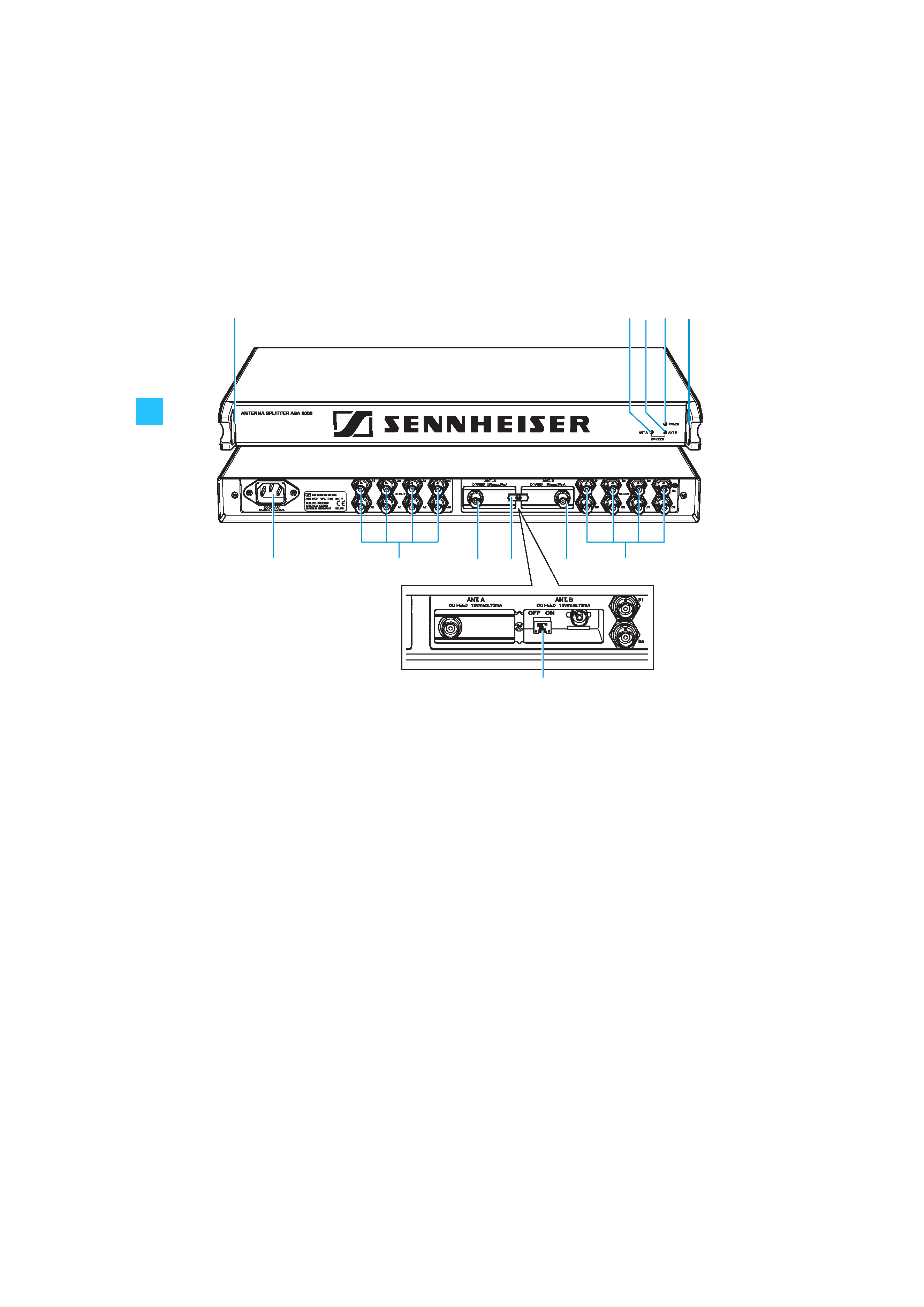
Operating elements
³ LED DC FEED ANT A (green)
· LED DC FEED ANT B (green)
» LED POWER (red)
¿ Threaded holes for rack-mounting
´ BNC sockets for antenna outputs, diversity section "B", B1 to B8
² Exchangeable wideband input module with BNC antenna input for diversity sec-
tion "B" ANT. B
¶ Catch for input modules
º Exchangeable wideband input module with BNC antenna input for diversity sec-
tion "A" ANT. A
¾ BNC sockets for antenna outputs, diversity section "A", A1 to A8
µ IEC mains socket
¸ Switches DC-Feed ANT A and DC-Feed ANT B for turning the DC supply voltage for
active antennas and antenna boosters on and off
(switches are located inside the input module slots
² and º)
´
¾
²
º
µ
·
³»
¿¿
¸
5
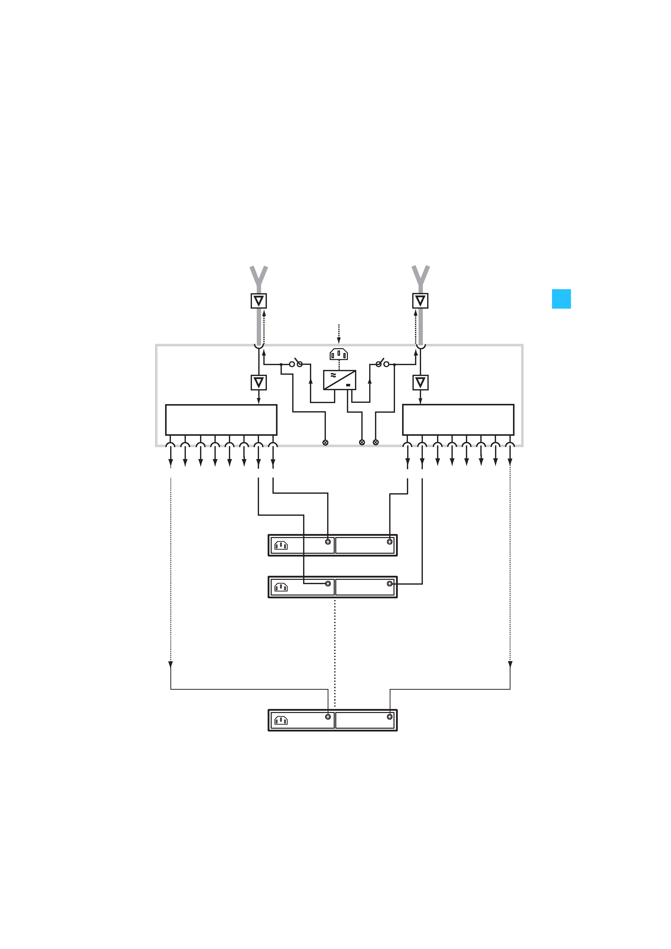
Connection diagram
The below connection diagram shows the connections for
an 8- or 16-channel system.
ASA 3000
ANT A
ANT B
Input B
ANT B
ANT A
Mains
Antenna booster
e.g. AB 1036
Antenna booster
e.g. AB 1036
Input A
POWER
B
A
B
A
B
A
1 : 8
1 : 8
1
2
3
4
5
6
7
8
8
7
6
5
4
3
2
1
EM 3000
EM 3000
EM 3000
1
2
8