Service Manual
FILE NO.
REFERENCE No.
SM5810290
CD Portable Radio
Cassette Recorder
MCD-ZX700F
(XE)
PRODUCT CODE No.
164 081 00
CONTENTS
Specification ..................................................................... 1
Laser beam safety precaution .......................................... 1
Tuner Adjustment ............................................................. 2
Tape Deck Adjustment ..................................................... 3
IC Block Diagram & Description ....................................... 3,7
Exploded View (Cabinet & Chassis) ................................ 4
Parts List .......................................................................... 5
Exploded View & Parts List(Tape Deck) ......................... 7
Wiring Connection ............................................................ 11
Schematic Diagram (Micom) ............................................ 12
Schematic Diagram (CD) ................................................. 14
Schematic Diagram (Radio) ............................................. 16
Schematic Diagram (Audio) ............................................. 18
Wiring Diagram (CD Main/Amp/Tu) ............................... 20
Wiring Diagram (Rectifier, Display, Power) .................... 21
- 1 -
CD CHANGER SECTION
Channels ..................................... 2-channel stereo
Sampling frequency .................... 44.1 kHz
Pick-up ........................................ semiconductor laser
Laser output ................................ 0.6 mW (Continuous wave max.)
Wave length ................................ 790 nm
Wow and Flutter .......................... Below measurable limits
Radio
Reception frequency
FM ........................................... 87.5 - 108 MHz (500 kHz step)
AM ........................................... 522 - 1,710 kHz (9 kHz step)
CASSETTE DECK
Track system ............................... 4 - track, 2 - channel stereo
Erasing system ........................... Magnet erase
Tape speed ................................. 4.75 cm/sec
Frequency response ................... 80 - 12,000 Hz
Fast forward and Rewind time .... Approx. 110 sec. (C - 60)
SPECIFICATIONS
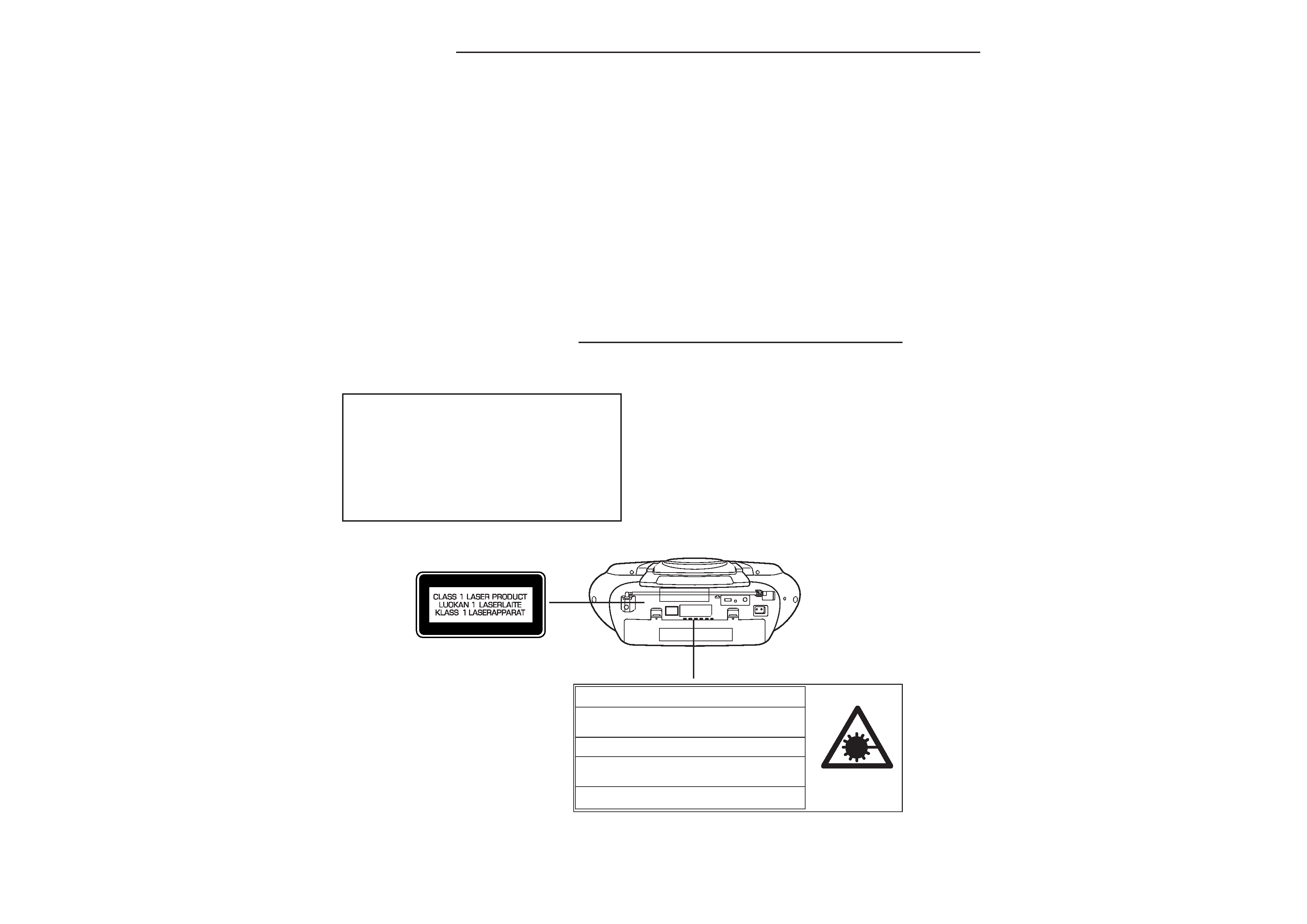
· Pickup that emits a laser beam is used on this CD section.
CAUTION :
USE OF CONTROLS OR ADJUSTMENTS OR
PERFORMANCE OF PROCEDURES OTHER
THAN THOSE SPECIFIED HEREIN MAY RESULT
IN HAZARDOUS RADIATION EXPOSURE.
LASER OUTPUT ................ 0.6 mW Max. (CW)
WAVE LENGTH ................. 790 nm
LASER BEAM SAFETY PRECAUTION
GENERAL SECTION
Output power .............................. 3 W/ch (DC max.)
Speaker ....................................... 10 cm X 2
Terminal ...................................... PHONE : 32
Power source .............................. AC : 110 - 120/220 - 240 V , 50/60 Hz
.................................................... DC : 12V, 8 "R20/D" batteries
Dimensions ................................. Approx. 480(W) x 167(H) x 258(D)
mm
Weight (approx.) ......................... 3.0 kg (without batteries)
Specifications subject to change without notice.
CAUTION INVISIBLE LASER RADIATION WHEN OPEN AND
INTERLOCKS DEFEATED. AVOID EXPOSURE TO BEAM.
ADVARSEL USYNLIG LASER STRÅLING VED ÅBNING, NÅR
SIKKERHEDSAFBRYDERE ER UDE AF FUNKTION, UNDGÅ UDS ÆTTELSE
FOR STRÅLING.
VARNING OSYNLIG LASER STRÅLNING NÄR DENNA DEL ÄR ÖPPNAD
OCH SPÄRR ÄR URKOPPLAD. STRÅLEN ÄR FARLIG.
VORSICHT UNSICHTBARE LASERSTRAHLUNG TRITT AUS, WENN
DECKEL GEÖFFNET UND WENN SICHERHEITSVERRIEGELUNG
ÜBERBRÜCKT IST. NICHT, DEM STRAHL AUSSETZEN.
VARO AVATTAESSA JA SUOJALUKITUS OHITETTAESSA OLET ALTTIINA
NÄKYMÄTTÖMÄLLE LASERSÄTEILYLLE. ÄLÄ KATSO SÄTEESEEN.
- 2 -
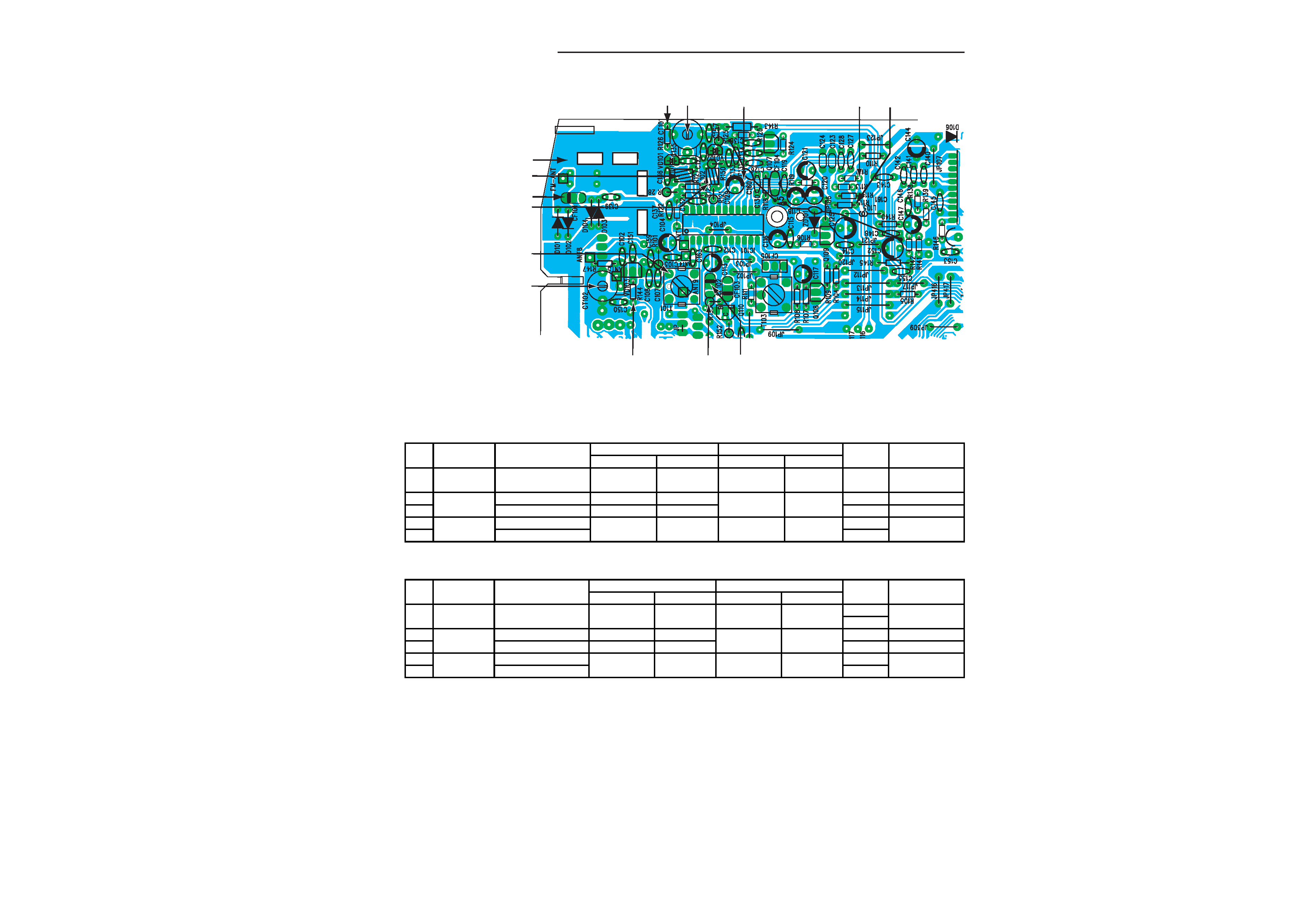
TP4
TP3
TP7
CT102
T101
L102
TP1
L101
TP2
TP6 CT101
TP5
TP8
TP9
· Use a plastic screw driver for adjustments.
· Adjust the intermediate frequency of AM and FM to the frequency of ceramic filter.
· Set of unit
Supply voltage
: DC 12V
Speaker
: 32
Function switch
: RADIO
PARTS LOCATION
TUNER ADJUSTMENTS
This is a basic adjustment.
1. AM ADJUSTMENT
Step
Adjusting
Tuning
Adjust-
VTVM
Circuit
Frequency
Instrument
Input
Instrument
Output
ment
Oscilloscope
1IF
999 KHz
AM sweep
Loop ANT.
VTVM
Speaker
T103
Max.
(450 KHz)
generator
oscilloscope
2
Tuning
522 KHz
---
---
Digital
TP7(H)
T101
1.5V±0.05V
3
coverage
1611 KHz
---
---
voltmeter
TP2(E)
---
7.4V±0.1V
4
Tracking
603 KHz
AM signal
Loop ANT.
VTVM
Speaker
AM COIL
Max.
5
1404 KHz
generator
oscilloscope
CT102
Input Connection
Output Connection
1. FM ADJUSTMENT
BAND SELECT SWITCH : FM
FM Dummy Antenna:75 unbalance
Step
Adjusting
Tuning
Adjust-
VTVM
Circuit
Frequency
Instrument
Input
Instrument
Output
ment
Oscilloscope
1IF98.0MHz
FM sweep
TP3(H)
VTVM
TP5(H)
---
Non Adjustment
10.7NHz
generator
TP4(E)
oscilloscope
TP4(E)
2
Tuning
87.5Hz
---
---
Digital
TP6(H)
L102
2.0V±0.1V
3
coverage
108.0MHz
---
---
voltmeter
TP2(E)
---
7.2V±0.1V
4
Tracking
90.0.MHz
FM signal
TP1(H)
VTVM
TP8(H)
L101
Max.
5
106.0MHz
generator
TP2(E)
oscilloscope
TP9(E)
CT103
Input Connection
Output Connection
- 3 -
2. HEAD AZIMUTH ADJUSTMENT
(1) Load the test tape(VTT-703, etc., 10 kHz) for azimuth
adjustment.
(2) Press the PLAY button.
(3) Use a cross-tip screwdriver to turn the screw for azimuth
adjustment so that the left and right output are maximized.
(4) Press the STOP button.
(5) After completion of the adjustment, use thread lock(TB-1401B)
to secure the azimuth-adjustment screw.
4. MOTOR SPEED ADJUSTMENT
(1) Insert the test tape(TCC-119, etc., 3,000 Hz).
(2) Press the PLAY button.
(3) Use a flat-tip screwdriver to turn the SVR(located inside the
rear of the motor) to adjust SVR so that the frequency counter
become 3,000 Hz.
5. CHECKING THE MECHANISM TORQUES AND TENSION
· Clean the head, capstan and pinch roller before making any measurement.
Measurement
Take-up torque
Back tension
Tape tension
Cassette for
PLAY : TW-211A
PLAY : TW-2111A
Drive-power cassete
measurement
F.FW/REW : TW-2231
TW-2412
PLAY
30 - 60 gr.cm
2.0 - 4.5 gr.cm
60 gr or more.
F.FWD
55 - 120 gr.cm.
-----
-----
REW
55 - 120 gr.cm.
-----
-----
1. HEAD REPLACEMENT
· After replacement, demagnetize the heads by using a degausser.
· Be sure to clean the heads before attempting to make any adjustments.
· All wiring should be returned to the original position after work is completed.
TAPE DECK ADJUSTMENTS
This is a basic adjustment.
3. AC BIAS FREQUENCY ADJUSTMENT
(1) Connect counter to T201(BS).
(2) R/P switch in recording state.
(3) Adjustment T801 a plastic screw , AC bias frequency : 80 kHz.
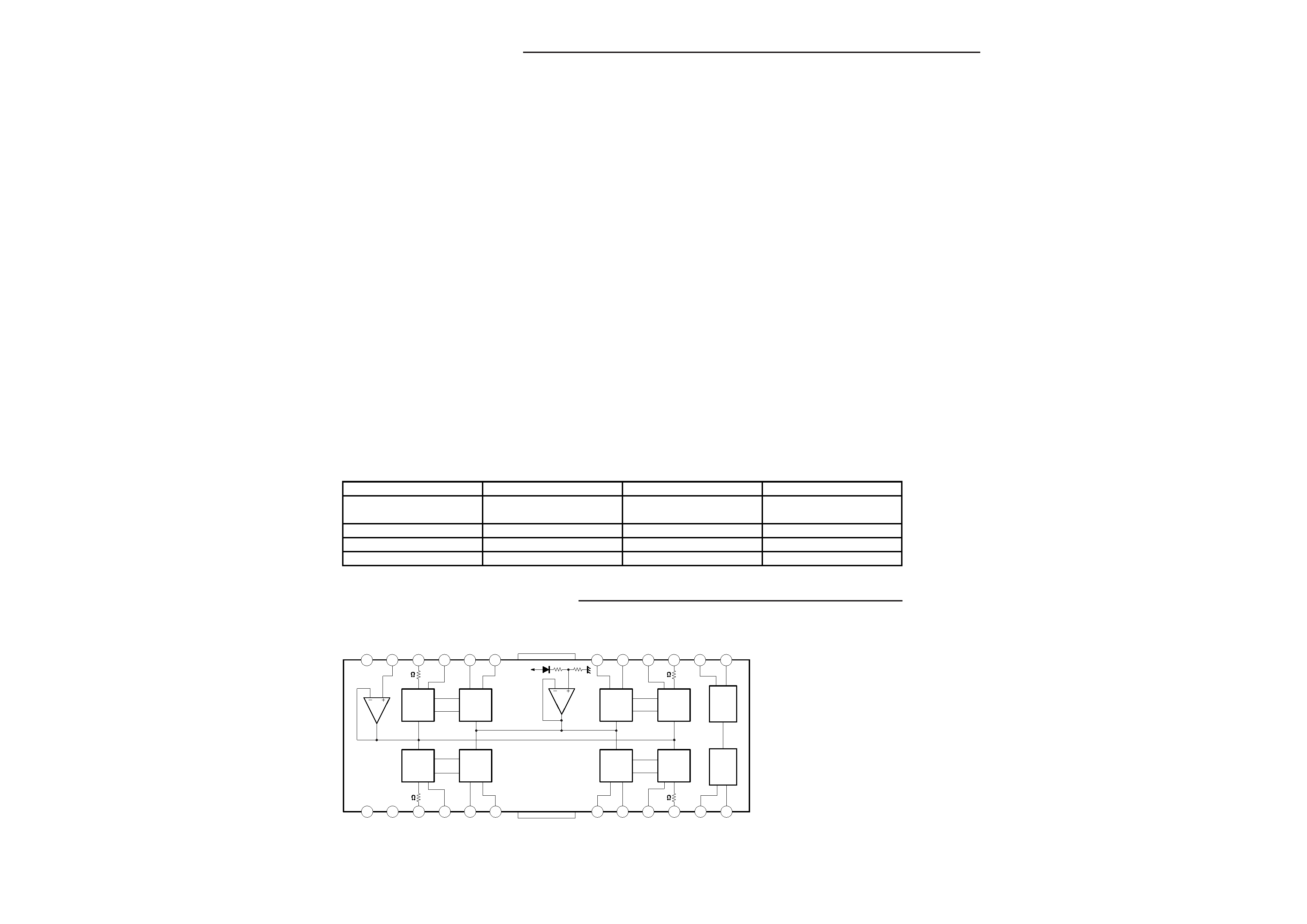
IC903 LA6541D(CD Driver)
12
3
4
56
789
10
11
12
13
14
15
16
17
18
19
20
21
22
23
24
Vcc
Vref
VIN4
VG4
Vo8
Vo7
GND
Vo6
Vo5
VG3
VIN3
CD
RES
Vcc
Mute
VIN1
VG1
Vo1
Vo2
GND
Vo3
Vo4
VG2
VIN2 Reg OUT Reg IN
Vcc
11k
11k
11k
11k
Level
Sift
BTL
Driver
BTL
Driver
Level
Sift
RESET
Regulator
Level
Sift
BTL
Driver
Level
Sift
BTL
Driver
IC BLOCK DIAGRAM & DESCRIPTION
-
4
-
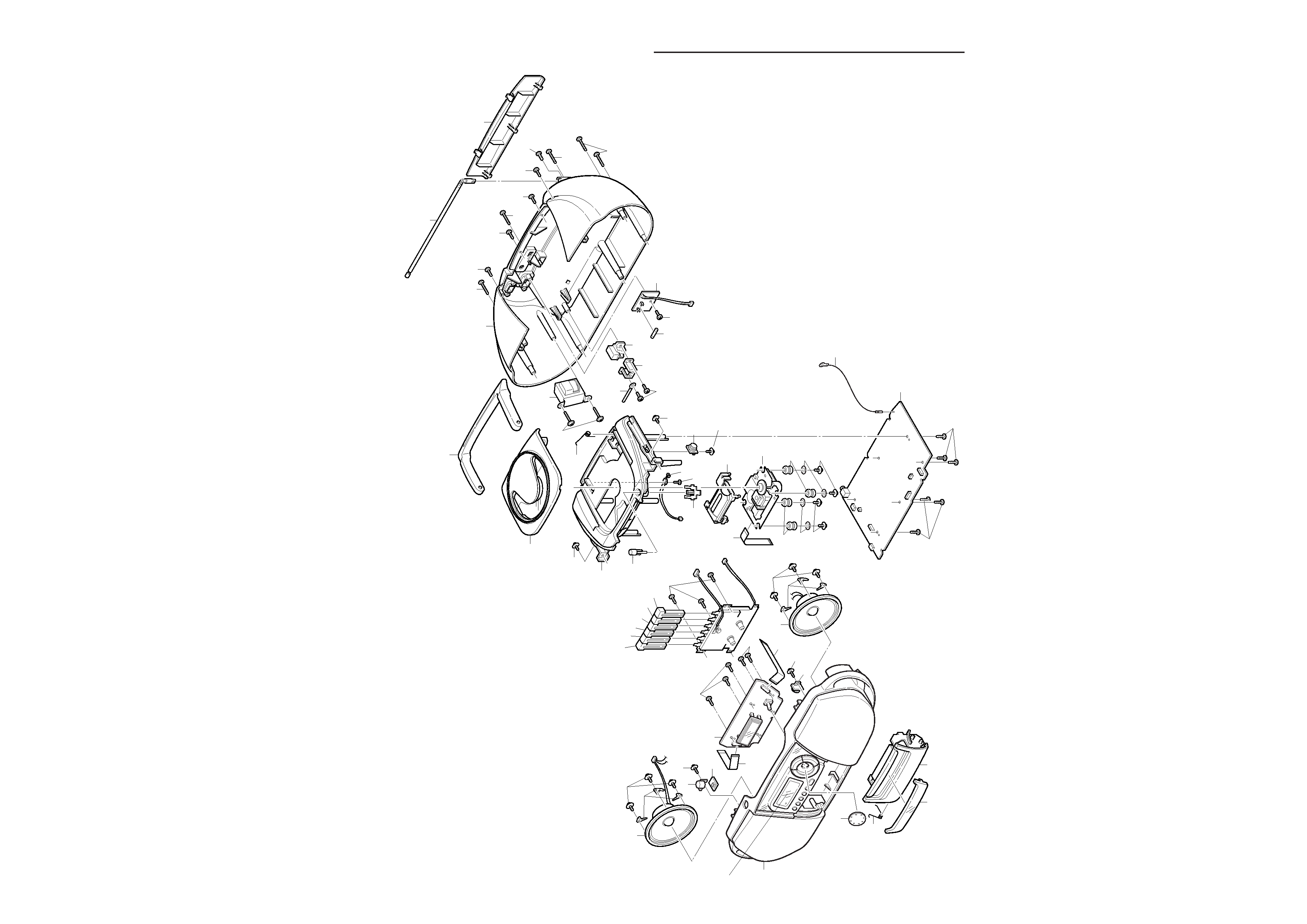
EXPLODED
VIEW(CABINET
&
CHASSIS)
12
3
7
8
Y01
Y01
Y02
Y04
Y05
Y09
Y09
Y14
Y16
Y17
Y15
Y18
Y18
Y18
60
Y20
Y20
Y18 Y21
Y18
Y18
Y10
Y11
Y11
Y12
Y13
Y13
Y12
Y03
Y03
8
9
51
51
52
53
71
72
15
14
17
18
19
21
23
27
28
29
31
74
56
73
32
33
58
59
57
34
38
32
30
54
55
26
16
11
4
39
40
Y06