Service Manual
FILE NO.
REFERENCE No.
SM5810282
PRODUCT CODE No.
164 083 03 300 (CA)
164 083 01 300F(XE)
164 083 04 350 (CA)
164 083 02 350F(XE)
CD Portable Radio
Cassette Recorder
MCD-ZX300 (CA)
MCD-ZX300F (XE)
MCD-ZX350 (CA)
MCD-ZX350F (XE)
MCD-ZX300
SERIES
MCD-ZX350
SERIES
SPECIFICATIONS
(CASSETTE SECTION)
Recording System ........... 4-track, , 2-channel stereo
Erasing System ............... Magnet erase
Tape speed ..................... 4.75 cm/sec.
Fast forward and
Rewind time .............. Approx. 110 sec. (C-60 tape)
Frequency range ............ 80 - 12,000 Hz (Normal tape)
(CD PLAYER SECTION)
Channels ......................... 2 channels stereo
S/N ratio .......................... 70 dB
Wow & Flutter .................. Below measurable limits
Sampling frequency ........ 44.1 kHz
Quantization .................... 16 bits linear/ch
Pickup light source .......... Semi-conductor laser
Pickup wave length ......... 790 nm
Laser output .................... Continuous wave max. 0.6 mW
(RADIO SECTION)
Tuning range ................... FM : 87.5 - 108 MHz (XE)
FM : 88.0 - 108 MHz (CA)
AM : 526.5 - 1,606.5 kHz (XE)
AM : 525.0 - 1,710.0 kHz (CA)
(GENERAL SECTION)
Power output ................... 2W/ch (DC max)
Speaker ........................... 10 cm x 2
Terminal impedance ....... PHONES : 32 ohms
Power source .................. AC : 230V, 50Hz (XE)
: 120V, 60Hz (CA)
DC : 12 V ("D"X8 batteries)
Dimensions ..................... 380 (W) x 170 (H) x 260 (D) mm
Weight (approx.) .............. 2.7 kg (Not including batteries)
Specifications subject to change without notice.
CONTENTS
Specification ..................................................................... Front
Laser beam safety precaution .......................................... 1
Tuner Adjustments ........................................................... 2
Tape Deck Adjustments ................................................... 3
Exploded View (Cabinet & Chassis) ................................ 4
Parts List .......................................................................... 5
Exploded View & Parts List(Tape Deck) ......................... 7
Block Diagram .................................................................. 7
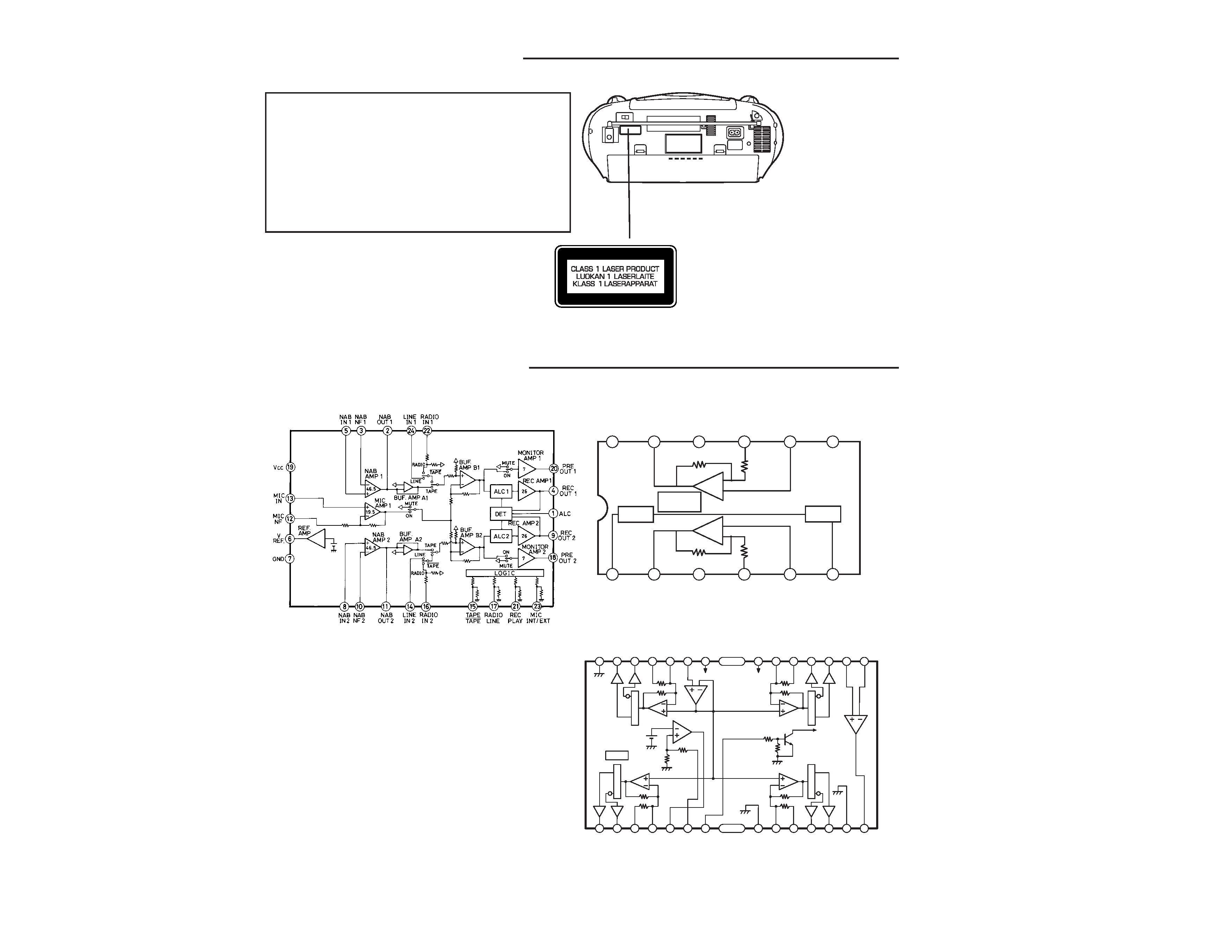
IC Block Diagram & Description ....................................... 8
Schematic Diagram (Main/CA) ........................................ 10
Schematic Diagram (Main/XE) ......................................... 12
Schematic Diagram (CD/CA) ........................................... 14
Schematic Diagram (CD/XE) ........................................... 16
Wiring Diagram (CD Main and Rec SW) ........................ 18
Wiring Diagram (Tuner, Display and Rectifier) .............. 19
Wiring Connection ........................................................... 20
- 1 -
CAUTION :
USE OF CONTROLS OR ADJUSTMENTS OR
PERFORMANCE OF PROCEDURES OTHER
THAN THOSE SPECIFIED HEREIN MAY RESULT
IN HAZARDOUS RADIATION EXPOSURE.
LASER OUTPUT ................ 0.6 mW Max. (CW)
WAVE LENGTH ................. 790 nm
IC301 LA4227(Power Amp.)
IC201 TA2068N (Cassette Preamp.)
+
STANDBY
SW
BIAS
CIRCUIT
Ch1
Ch2
THERMAL
SHUT DOWN
PROTECTION
-
+
-
1
2
3
4
5
6
7
8
9
10
11
12
STANDBY
OUT2
BS2
NF2
IN2
DC
(FILTER)
VCC
OUT1
BS1
NF1
IN1
PRE GND
IC903 MM1469XH (CD Driver)
IC BLOCK DIAGRAM & DESCRIPTION
28
27
26
25
24
23
22
21
20
19
18
17
16
15
123456
7
89
10
11
12
13
14
Vcc
Vcc
DRIVER MUTE
D.BUF
D.BUF
D.BUF
D.BUF
D.BUF
D.BUF
D.BUF
D.BUF
Le
ve
lshift
Le
ve
lshift
Le
ve
lshift
Le
ve
lshift
T.S.D
· Pickup that emits a laser beam is used on this CD section.
LASER BEAM SAFETY PRECAUTION
- 2 -
T103
T102
JW106
T101
T104
IC101 JW105 L101 VC102 VC103 L102 VC104 VC103
FM ANT
FM (E)
MW ANT
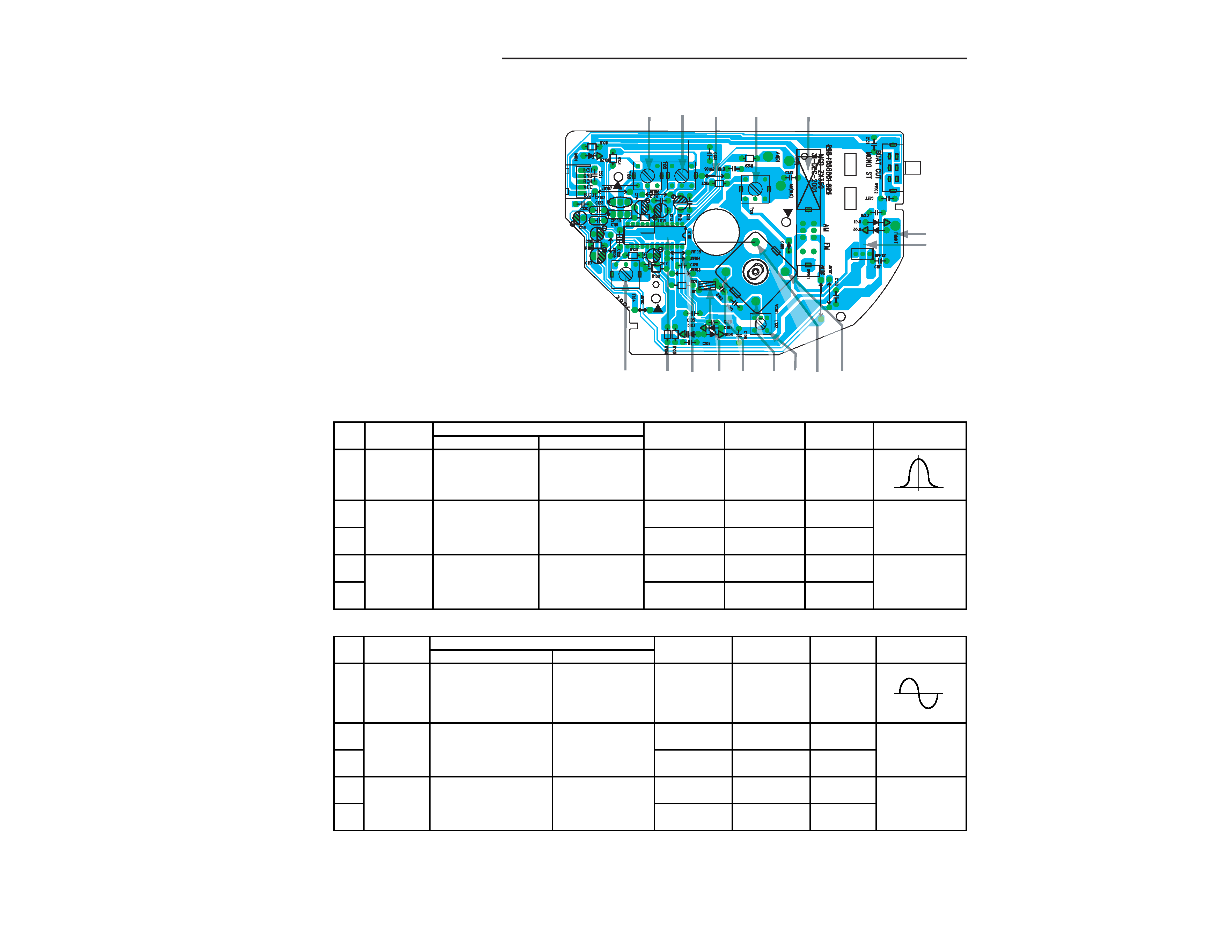
1. AM ADJUSTMENT
Band switch : MW
Step Adjusting
Connection
S G
Position of
Adjust-
VTVM
Circuit
Input
Output
Frequency
tuning dial
ment
Oscilloscope
Closed the output
Connect sweep
1IF
terminal by sweep
generator to
465 kHz
Low
T103
generator, it place
IC101(19(H)) and
to MW ANT.
C107(E).
2
515 kHz
Low end
T101
Tuning
Connect AM SG to
Connect VTVM to
Max.
3
coverage
TEST LOOP.
speaker terminals.
1640 kHz
High end
VC103
4
600 kHz
600 kHz
MW COIL
Tracking
Connect AM SG to
Connect VTVM to
Max.
5
TEST LOOP.
speaker terminals.
1400 kHz
1400 kHz
V104
· Use a plastic screw driver for adjustments.
· Adjust the intermediate frequency of AM and FM to the frequency of ceramic filter.
· Set of unit
Supply voltage
: DC 12V
Speaker
: 4 ohms
Standard output
: 50 mW (450 mV)
Function switch
: RADIO
PARTS LOCATION
TUNER ADJUSTMENTS
This is a basic adjustment.
2. FM ADJUSTMENT
Band switch : FM
FM Dummy antenna : 75 ohms unbalance
Step Adjusting
Connection
S G
Position of
Adjust-
VTVM
Circuit
Input
Output
Frequency
tuning dial
ment
Oscilloscope
T104 and
1
IF
10.7MHz
Low
T102
2
87MHz
Low end
L102
Tuning
Connect FM SG to
Connect VTVM to
Max.
3
coverage
FM ANT (H) & FM (E).
speaker terminals.
109MHz
High end
VC101
4
90.0MHz
90.0MHz
L101
Tracking
Connect FM SG to
Connect VTVM to
Max.
5
FM ANT (H) & FM (E).
speaker terminals.
106.0MHz
106.0MHz
VC102
Connect sweep
generator to
IC101 (24pin)
and C107(E)
Connect VTVM
generator to
IC101 (19PIN)
and C1075 (E).
- 3 -
2. HEAD AZIMUTH ADJUSTMENT
(1) Load the test tape(VTT-703, etc., 10 kHz) for azimuth
adjustment.
(2) Press the PLAY button.
(3) Use a cross-tip screwdriver to turn the screw for azimuth
adjustment so that the left and right output are maximized.
(4) Press the STOP button.
(5) After completion of the adjustment, use thread lock(TB-1401B)
to secure the azimuth-adjustment screw.
3. MOTOR SPEED ADJUSTMENT
(1) Insert the test tape(TCC-119, etc., 3,000 Hz).
(2) Press the PLAY button.
(3) Use a flat-tip screwdriver to turn the SVR(located inside the
rear of the motor) to adjust SVR so that the frequency counter
become 3,000 Hz.
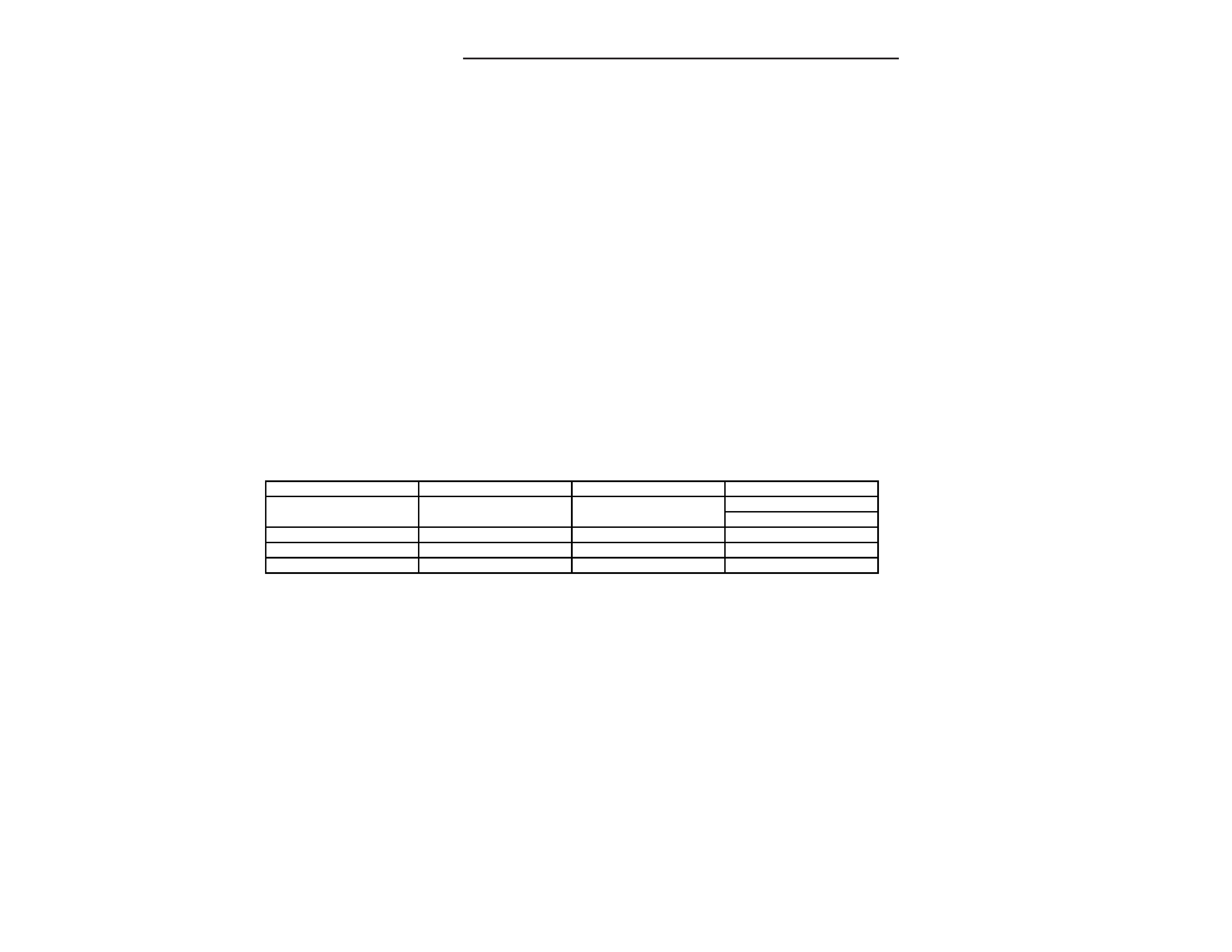
4. CHECKING THE MECHANISM TORQUES AND TENSION
· Clean the head, capstan and pinch roller before making any measurement.
Measurement
Take-up torque
Back tension
Tape tension
Cassette for
PLAY : TW-211A
PLAY : TW-2111A
Drive-power cassete
measurement
F.FW/REW : TW-2231
TW-2412
PLAY
30 - 60 gr.cm
2.0 - 4.5 gr.cm
60 gr or more.
F.FWD
55 - 120 gr.cm.
-----
-----
REW
55 - 120 gr.cm.
-----
-----
1. HEAD REPLACEMENT
· After replacement, demagnetize the heads by using a degausser.
· Be sure to clean the heads before attempting to make any adjustments.
· All wiring should be returned to the original position after work is completed.
TAPE DECK ADJUSTMENTS
This is a basic adjustment.
-
4
-
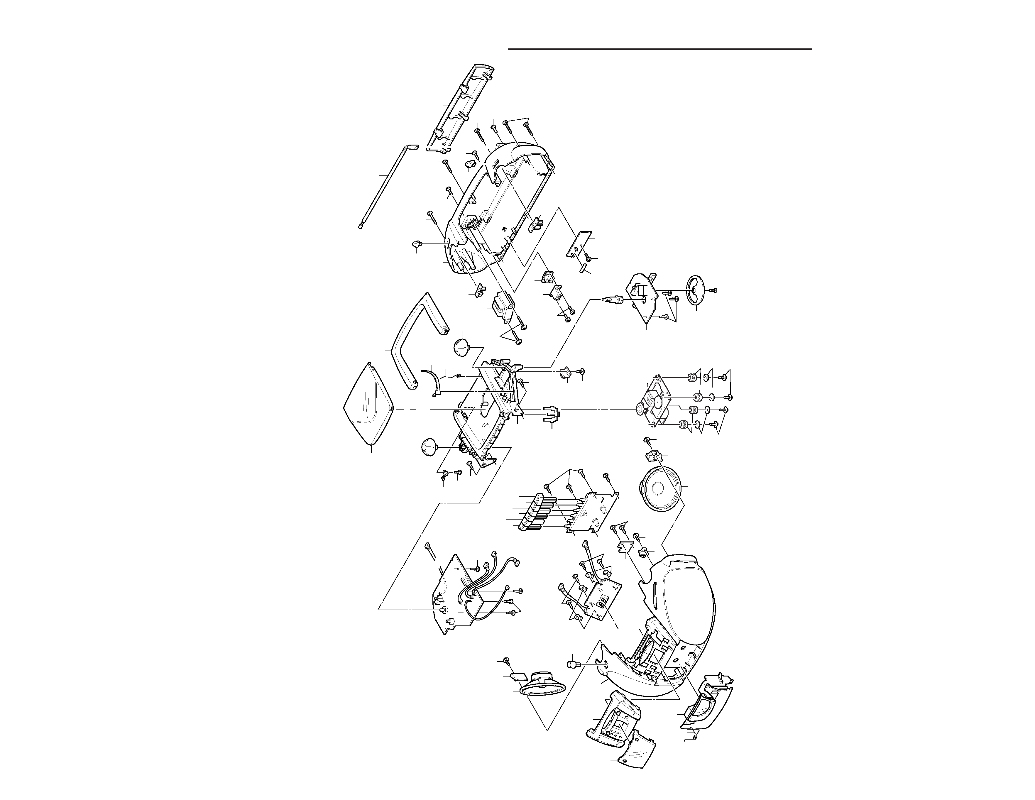
EXPLODED
VIEW(CABINET
&
CHASSIS)
10
10
12
11
11
71
72
13
14
15
16
17
18
33
33
30
29
28
27
20
26
36
37
34
56
35
38
39
40
31
1
25
9
44
51
51
54
53
55
57
73
75
74
Y01
Y01
Y02
Y02
Y03
Y04
Y05
Y05
Y14
Y14
Y13
Y13
Y12
Y07
Y07
Y10
Y11
Y11
Y17
Y18
Y20
Y21
Y21
Y21
Y21
Y22
Y23
Y23
Y16
Y15
3
4
5
6
7
8
2