Index
1. Safety instructions..................................................................................................................................................................................................1
2. WARNING .............................................................................................................................................................................................................1
3. Precaution against X-Rays .....................................................................................................................................................................................1
4. Technical characteristics........................................................................................................................................................................................2
5. Safety .....................................................................................................................................................................................................................2
6. EMC (Electromagnetic Compatibility).....................................................................................................................................................................2
7. Factory special mode..............................................................................................................................................................................................3
8. "HOTEL" and "RENTAL" modes............................................................................................................................................................................3
9. Automatic channel search reactivating ...................................................................................................................................................................3
10. Block diagram.......................................................................................................................................................................................................4
11. Power supply........................................................................................................................................................................................................5
12. Microprocessor and Teletext ................................................................................................................................................................................5
13. Video processor/Comb filter .................................................................................................................................................................................5
13.1 Video Intermediate Frequency Section ..........................................................................................................................................................5
13.2 Horizontal and vertical synchronisation..........................................................................................................................................................5
13.3 Geometry .......................................................................................................................................................................................................6
13.4 Filters and video switches..............................................................................................................................................................................6
13.5 Colour decoder ..............................................................................................................................................................................................6
13.6 RGB Processing............................................................................................................................................................................................6
13.7 RGB Control ..................................................................................................................................................................................................7
13.8 Supply and bandgap decoupling....................................................................................................................................................................7
14. Audio processor/A3D Surround/Output amplifiers/Sound IF................................................................................................................................7
15. Service menu........................................................................................................................................................................................................8
16. Adjustment and repair procedures .....................................................................................................................................................................10
16.1 Notes about the adjustment: ........................................................................................................................................................................10
16.2 Switch-on sequence. ...................................................................................................................................................................................11
16.3 Protect modes and failure indication ............................................................................................................................................................11
16.4 Protect mode inhibition ................................................................................................................................................................................11
16.5 Power supply repair procedure ....................................................................................................................................................................11
16.6 Non-volatile memory (NVM) replacement, IC125.........................................................................................................................................11
17. Failure location flow-charts.................................................................................................................................................................................12
18. Complete PCB codes for after sales service ......................................................................................................................................................15
19. CHASSIS ELECTRICAL PARTS LIST CE21FN1-E / CE25FN1-E / CE28FN1-E ...........................................................................................16
20. CE21FN1-E CABINET PARTS LIST ................................................................................................................................................................17
21. CE25FN1-E CABINET PARTS LIST ................................................................................................................................................................18
22. CE28FN1-E CABINET PARTS LIST ................................................................................................................................................................19
23. Parts List ............................................................................................................................................................................................................20
CE28FN1-E
CE25FN1-E
CE21FN1-E
Service Manual
Models:
CRT 28" A59EAK071X11
CRT 25" A66EAK071X11
CRT 21" A51EAL155X10
CRT 21" A51EAL155X11
CHASSIS No 2103
EB5-A
Colour Television
Ref. Nº MS CE25FN1-E
16-11-1998
Give complete "SERVICE PART No" for parts order or
servicing, it is shown on the rating sheet on the cabinet
back of the TV set.
Note
This TV receiver will not work properly in foreign
countries where the television transmission system and
power source differ from the design specifications. Refer
to the specifications for the design specifications.
Service Manual MS CE25FN1-E
1
1. Safety instructions
Read this page before doing any operation of adjustment, maintenance or repair the TV set described.
Only skilled personnel of Sanyo Technical Service should do the adjustment, maintenance or repair of TV set.
2. WARNING
For the correct and safe use of the TV set, it is essential that the service personnel follow the process of safety
generally accepted and the safety precautions specified in this manual.
An isolation transformer should be connected in the power line between the receiver and the AC line when a
service is performed on the primary side of the converter transformer of the set.
3. Precaution against X-Rays
The primary source of X-RADIATION in the television receiver is the picture tube. The picture tube is specially
constructed to limit X-RADIATION emissions. For continued X-RADIATION protection, the replacement tube
must be the same type as the original including suffix letter. Excessive high voltage may produce potentially
hazardous X-RADIATION. To avoid such hazards, the high voltage must be maintained within specified limit. If
high voltage exceeds specified limits, take necessary corrective action. Follow the instructions carefully for +B1
volt power supply adjustment, and high voltage adjustment to maintain the high voltage within the specified
limits.
COMPLIANCE TO STANDARDS
All of those marked with X or
must be
replaced with original parts
WARNING! This TV set contains components which
are particularly sensitive to static electricity (ESD).
It is recommended that all due precaution be taken
handling integrated circuits and semiconductors.

Service Manual MS CE25FN1-E
2
4. Technical characteristics
Cathode-ray tubes
21" (54 cm) Model CE21FN1-E
25" (65 cm) Model CE25FN1-E
28" (70 cm) Model CE28FN1-E
In-Line gun type. Black Matrix.
Tuning system
Voltage synthesis, 100 programs in non volatile memory, AFT, fine tuning (first
10 programs), automatic, semiautomatic and manual channel search.
Program selection
Sequential selection from the controls on the set. Direct selection of any
program from the remote-control device.
Receiving channels
(Cable and Aerial)
Band I channels E2 ... E4; S1 ... S10;
Band III channels E5 ... E12; S11 ... S41;
Band IV-V channels E21 ... E69.
TV system
B/G and D/K systems
Colour system
PAL, NTSC 4.43
Audio power
2 x 8 W rms, 10% distortion
Speakers
2 x 8
, full range
Aerial
External aerial-socket 75
IEC.
Headphones
Jack stereo 3,5 mm (with independent control).
AV connectors
1 SCART connector 21-pin, standard CENELEC AV and RGB.
1 SCART connector 21-pin, standard CENELEC AV and S-video.
1 RCA type Video input (front).
2 RCA type Audio R/L input (front).
Power source
220 Vac ... 240 Vac, 50 Hz.
Power consumption
CE25FN1-E and CE28FN1-E
108 W (maximum).
72 W (IEC 107-1)
2.5 W (stand-by).
Power consumption
CE21FN1-E
87 W (maximum).
65 W (IEC 107-1)
2.3 W (stand-by).
STEREO Systems
Nicam and A2.
Sound effects
Active 3D Surround. Pseudo Stereo. Bass boost. Auto volume
Comb Filter
Models CE25FN1-E and CE28FN1-E
Clock function
Auto capture from teletext.
Alarm function
Programmable over 24 hours.
Timer function
Switch on and off are programmable over 24 hours.
Teletext
Level 1.5 Flof, Top and List. 10 teletext pages memory.
East european TXT included.
Hotel mode
Can be programmed in Hotel and Hotel Rental mode.
5. Safety
It fulfils the safety requirements established in the regulation:
· EN 60065:93
6. EMC (Electromagnetic Compatibility)
It fulfils the EMC requirements established in the regulation:
· EN 55013:1990/A12:1994
· EN 55020:1994
· EN 60555-2:1987

Service Manual MS CE25FN1-E
3
7. Factory special mode
The factory mode is a special TV working mode intended to help in the manufacturing process and it is
identified on the screen with the message "FAC". This mode is never suited for customer use.
The main differences respect to normal mode are:
1- The standby mode is always disabled.
2- The Blue-back (no sync. signal present) is disabled.
3- The customer adjustments ( volume, contrast ...) work faster.
In case of finding the TV set in Factory mode, it must be taken out of this state. To do so, enter the clock
setting menu on the customer OSD and then exit.
8. "HOTEL" and "RENTAL" modes
The TV set has a special mode of operation that is adapted for use in hotels, hospitals... Its main purpose is to
avoid the manipulation of the basic TV settings. This mode is stored in NVM, so it is maintained even though
the TV set is disconnected from the mains.
Its main features are:
1. The maximum volume level is limited to the volume chosen when the mode is entered.
2. Channel searching and fine tuning are disabled.
3. The TV set always switches on with the normalisation settings and users can not memorise any of their
personal preferences.
4. Language selection and child lock are disabled.
5. It is possible to force the TV set to always switch-on in a selected program between the 1st and 8th or AV1.
To activate this mode, hold down the "VOL -" front key and simultaneously, press the "RECALL" remote control
key. A message like " HOTEL: 00 " will appear waiting for two digits entry.
The most significant digit indicates the selected mode:
`0': normal mode
`1': HOTEL mode
`2': RENTAL mode
The second digit indicates the programme in which the set will switch on:
`0': the same as it was selected when the TV set was switched off (normal mode)
`1' to `8': always this programme selection (1 to 8).
`9': always AV1 mode
The `RENTAL' mode has the same features as the `HOTEL' mode and additionally the front keys are inhibited
so it is only possible to change the program with the remote control. In order to exit from this mode, the colour
saturation level must be set to zero.
9. Automatic channel search reactivating
In order to reset the initial automatic channel search function, start a channel search in AUTO mode from the
user tuning menu and switch-off the TV set before any station is found. The next time the TV set is switched
on, it will start an automatic channel-search.
Service Manual MS CE25FN1-E
4
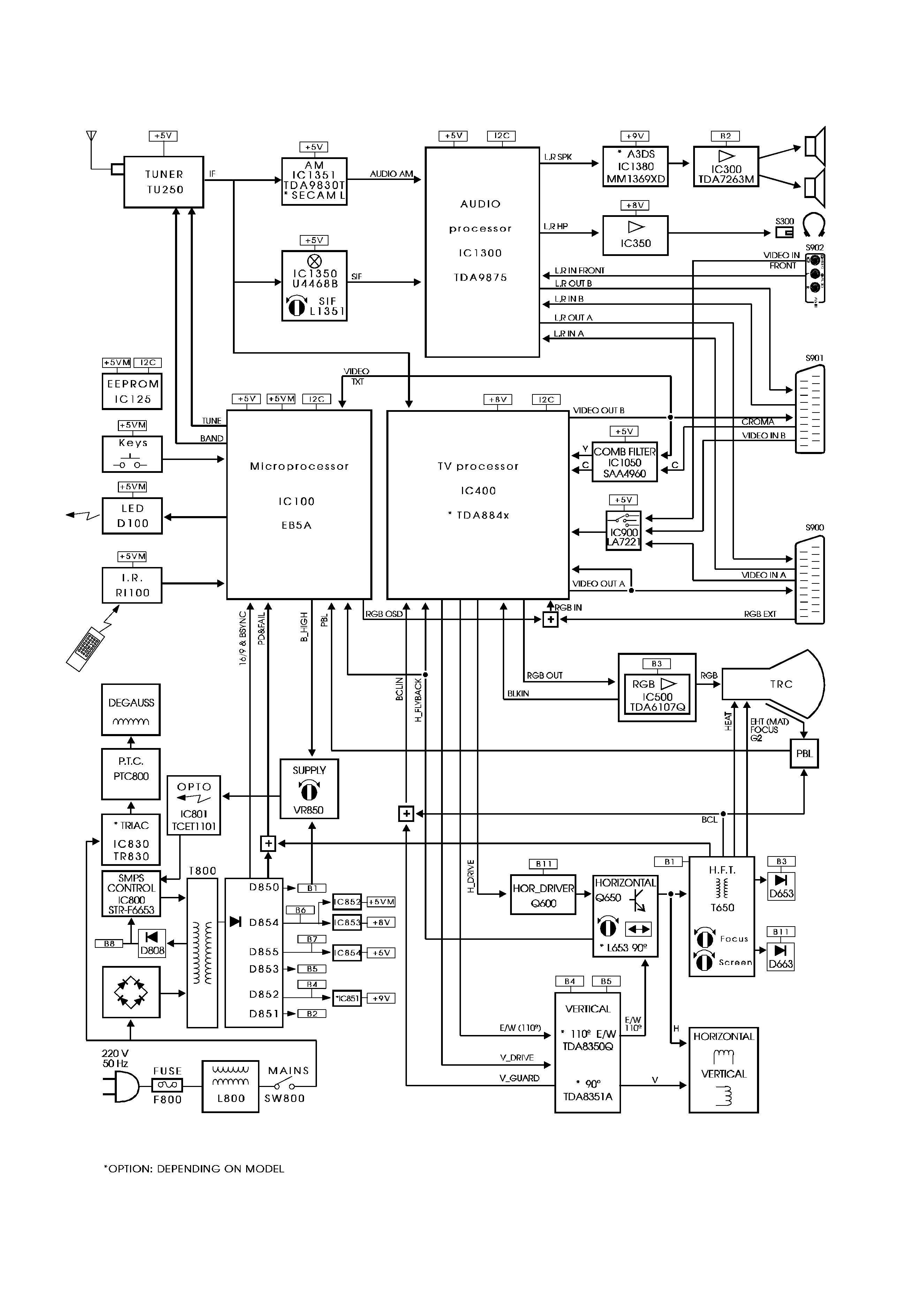
10. Block diagram