Specifications
Power Rating . . . . . . . . . . . . . . . . . . . . . . . . 120VAC
95W (Avg), 1.8A (Max)
Antenna Input Impedance . . . . . . . . . . . . . . . . . 75
UHF/VHF/CATV
Receiving Channel . . . . . . . . . . . . . . . . 2 - 13 (VHF),
14 - 69 (UHF),
01, 14-94, 95-125 (CATV)
Remote Ready . . . . . . . . . . 25 Key Remote Control
Sound Output . . . . . . . . . . . . . . . . . . . . . . 2.0 W/CH
Intermediate Frequency
Picture IF Carrier . . . . . . . . . . . . . . . . . . 45.75MHz
Sound IF Carrier . . . . . . . . . . . . . . . . . . 41.25MHz
Color Sub Carrier . . . . . . . . . . . . . . . . . 42.17MHz
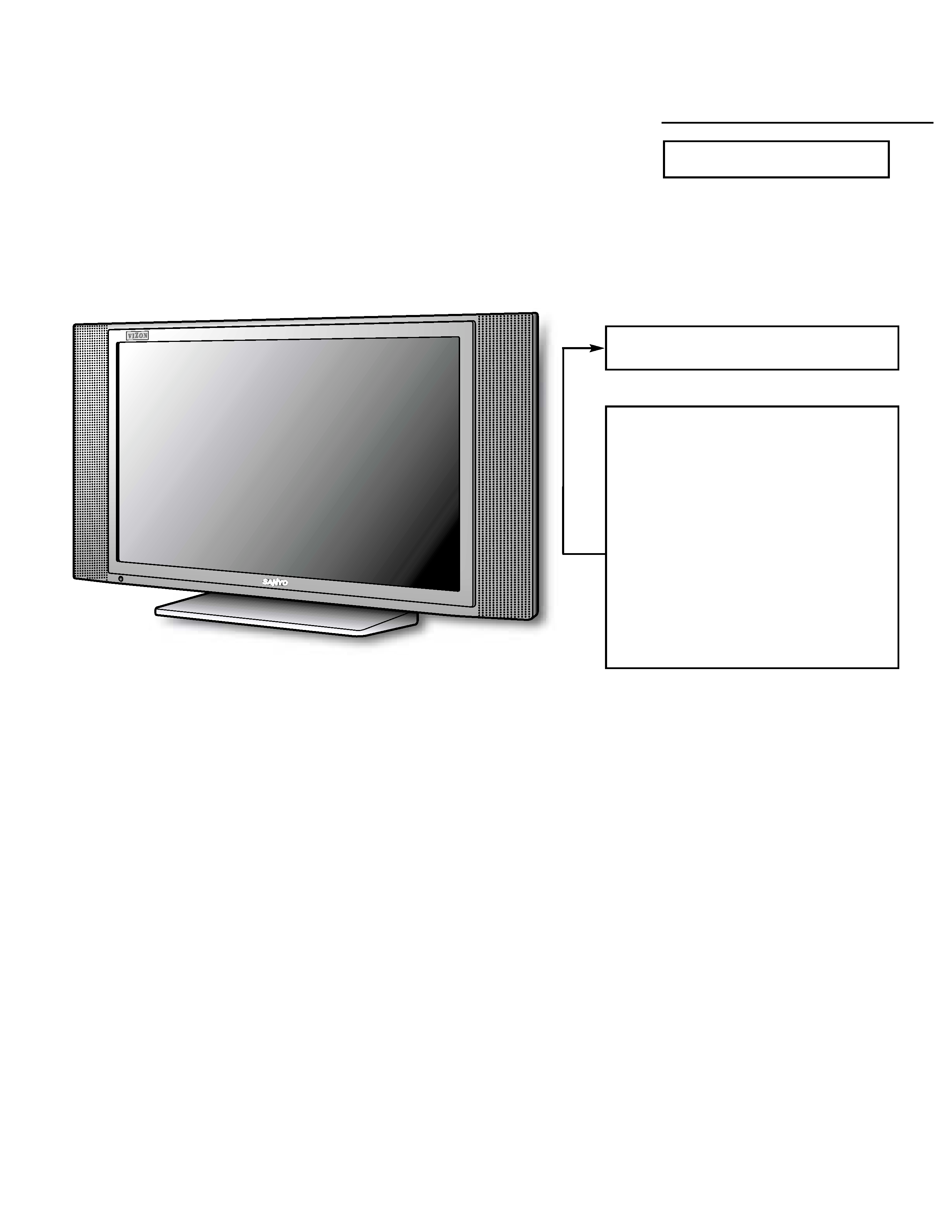
LCD . . . . . . . . . . . . . . . . . . . . . . . . . . . . . V230W1-L02
Cabinet Dimensions
Width . . . . . . . . . . . . . . . . . . . . . . . . . . . . . 692mm
Height . . . . . . . . . . . . . . . . . . . . . . . . . . . . 385mm
Depth including base . . . . . . . . . . . . . . . . 181mm
REFERENCE No.
SM780104
DP23625, N2TE, PRODUCT CODE 111377004
Contents
Safety Instructions . . . . . . . . . . . . . . . . . . 2
Service Adjustments . . . . . . . . . . . . . 3 - 10
Power Failure Circuit . . . . . . . . . . . . . . . 11
Mechanical Disassemblies . . . . . . . 12 13
Chassis Electrical Parts List . . . . . . 14 - 25
Cabinet Parts List . . . . . . . . . . . . . . . . . . 26
Component and Test Point
Locations . . . . . . . . . . . . . . . . . . . 27 31
Block Diagrams . . . . . . . . . . . . . . . . 32 36
Trouble Shooting Flow Charts . . . . 37 39
Control Port Functions. . . . . . . . . . . 40 41
Schematic Notes . . . . . . . . . . . . . . . . . . . 42
Pin Layouts. . . . . . . . . . . . . . . . . . . . . . . . 42
Capacitor and Resistor Codes . . . . . . . . 43
Schematic Diagrams . . . . . . . . . . . . 45 - 56
AS
FILE NO.
SERVICE MANUAL
Remote Control Digital
Color Television
DP23625 (U.S.A.)
(CANADA)
ORIGINAL VERSION
Chassis No. 23625-00
NOTE: Match the Chassis No. on
the unit's back cover with
the Chassis No. in the
Service Manual.
If the Original Version
Service Manual Chassis
No. does not match the
unit's, additional Service
Literature is required. You
must refer to "Notices" to the
Original Service Manual
prior to servicing the unit.
-- 2 --
SAFETY INSTRUCTIONS
SAFETY PRECAUTIONS
1. Comply with all caution and safety-related notes provided
on the side of the cabinet, inside the cabinet, and on the
chassis,
2. When replacing a chassis in the cabinet, always be certain
that all the protective devices are installed properly, such
as control knobs, adjustment covers, shields and barriers.
3. Before replacing the back cover of the set, thoroughly
inspect the inside of the cabinet to see that no stray parts
or tools have been left inside.
ANTENNA COLD CHECK
Remove AC plug from the 120 VAC outlet and place a
jumper across the two blades. Connect one lead of an ohm-
meter to the jumpered AC plug, and touch the other lead to
each exposed antenna terminal (UHF and VHF antenna ter-
minals). The resistance must measure between 1M ohm and
5.2M ohm. Any resistance value below or above this range
indicates an abnormality which requires corrective action.
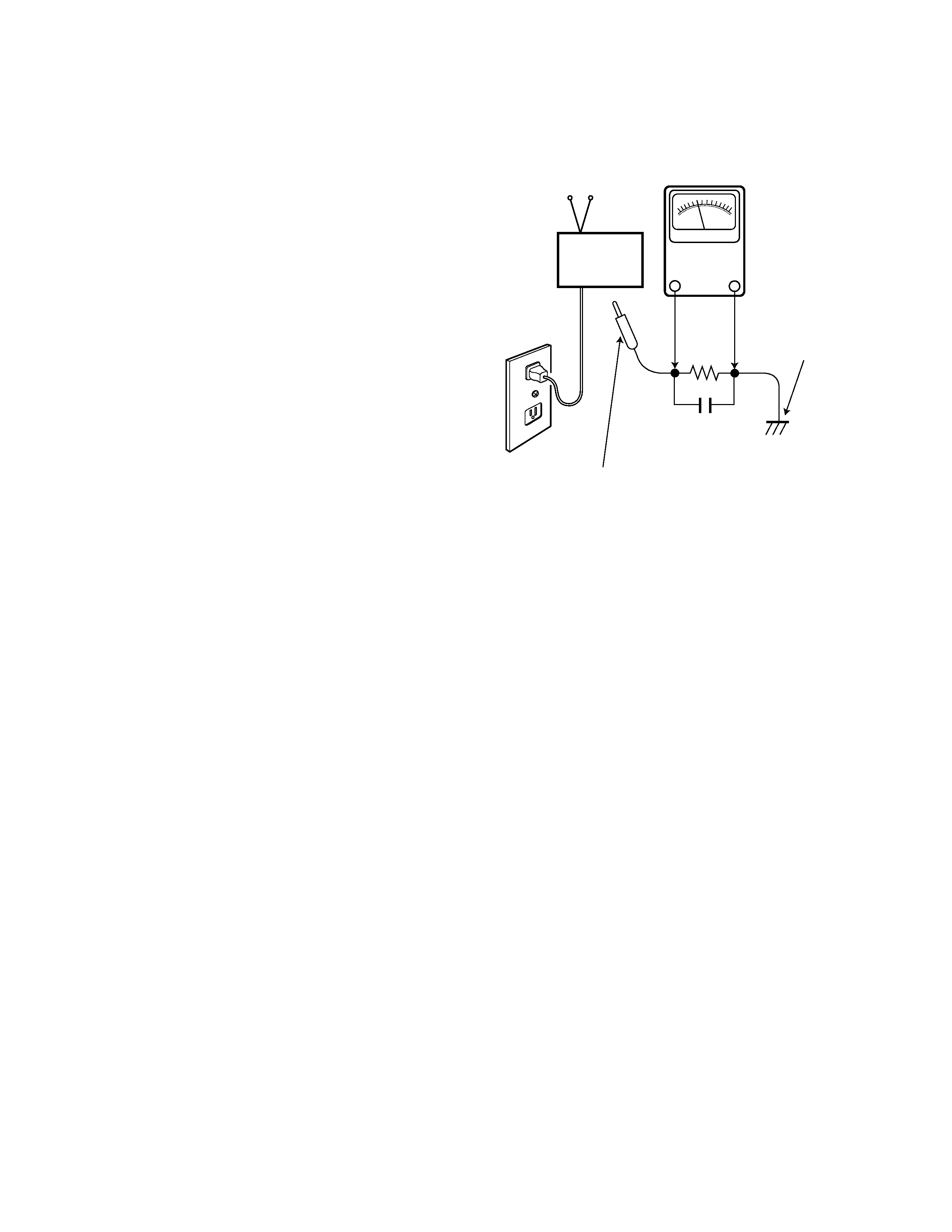
LEAKAGE CURRENT CHECK
Plug the AC line cord directly into a 120 VAC outlet. (Do not
use an isolation transformer for this check.) Use an AC volt-
meter, that has 5000 ohms per volt or more sensitivity.
Connect a 1500 ohm 10 watt resistor, paralleled by a 0.15 µF
150 VAC capacitor, between a known good earth ground
(water pipe, conduit, etc.) and all exposed metal parts of the
cabinet (antennas, handle bracket, metal cabinet, screw
heads, metal overlays, control shafts, etc.). Measure the AC
voltage across the 1500 ohm resistor. The AC voltage
should not exceed 750 mV. A reading exceeding 750 mV
indicates that a dangerous potential exists. The fault must
be located and corrected. Repeat the above test with the
receiver power plug reversed.
NEVER RETURN A RECEIVER TO THE CUSTOMER
WITHOUT TAKING THE NECESSARY CORRECTIVE ACTION.
PRODUCT SAFETY NOTICE
When replacing components in a receiver, always keep in
mind the necessary product safety precautions. Pay special
attention to the replacement of components marked with a
star (
#) in the parts list and in the schematic diagrams. To
ensure safe product operation, it is necessary to replace
those components with the exact same PARTS.
0.15 µF 150V AC
1500 ohm
10 watt
Good earth ground
such as a water pipe,
conduit, etc.
AC OUTLET
TELEVISION
RECEIVER
READING SHOULD NOT EXCEED 750 mV.
AC VOLTMETER
(5000 ohms per volt or more sensitivity)
To be touched to all of exposed metal parts.
Voltmeter Hook-up for Leakage Current Check.
GENERAL
This set has an On-screen Service Menu system included in
the CPU that allows remote operation for most of the ser-
vice adjustments.
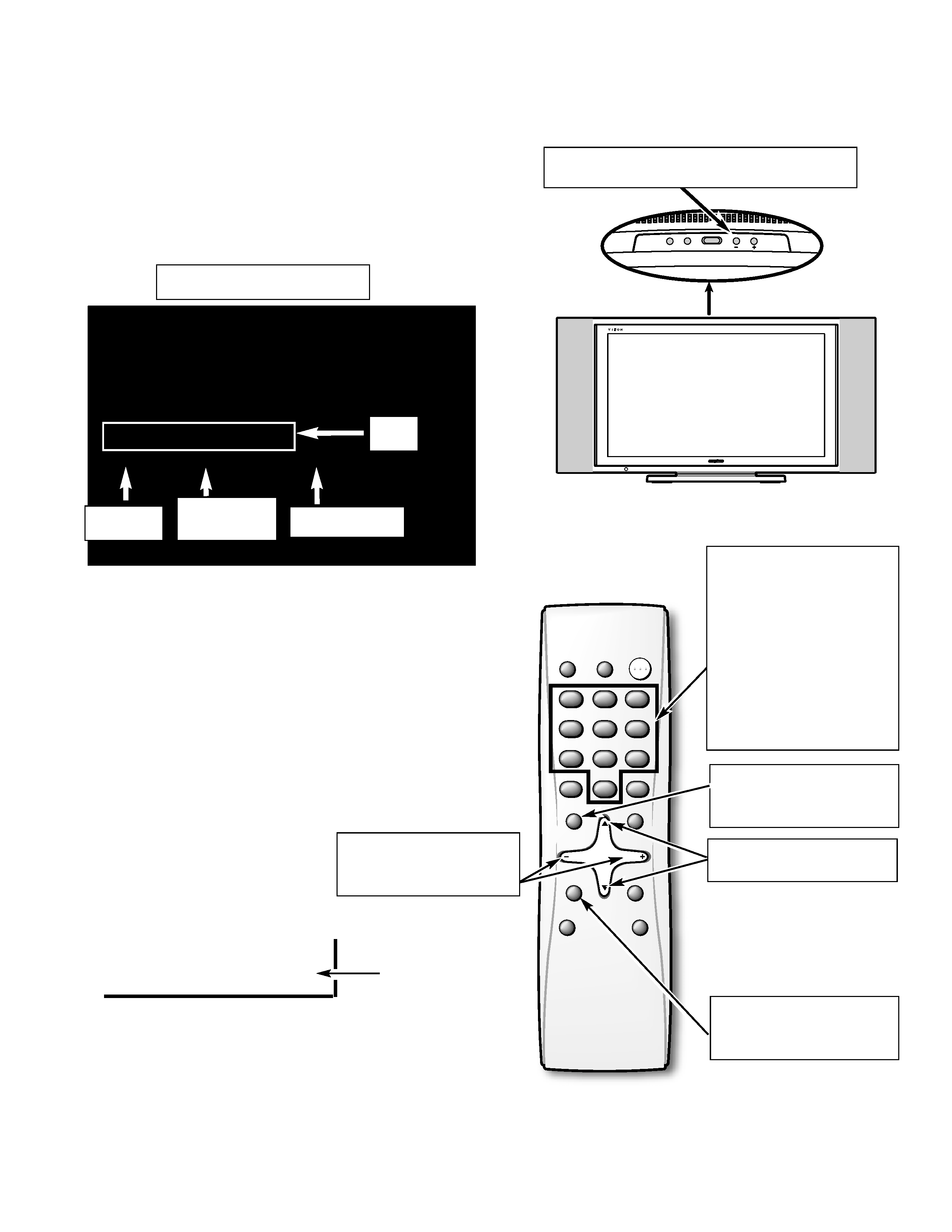
ON-SCREEN SERVICE MENU SYSTEM
1. Enter the Service Menu:
· While pressing the Volume () button on the televi-
sion, press the Number Key 1 on the remote control
unit. The Service Menu will now appear.
2. Service Adjustments:
· Press the L or M key to select the desired service
menu item you want to adjust. See page 4 for the
On-screen Service Menu.
Note: Press the Mute key to skip up 16 items.
· Use the + or key or number keys to adjust the data.
The + or keys will increase or decrease the data
sequentially. The number keys (0 ~ 7) toggle only
their respective bits between 1 and 0 and are used to
change the Sub-Address. For example to change bit
5 press the number 5 key. See below.
Note: Using the + or is not recommended due to possi-
ble rapid changes.
3. Exit from the Service Menu:
· Press the MENU key to turn off
the Service Menu display.
255_ 255
255 / 255 / 255
255 : 255 : 255__00002
M037___S8A __TV____RC00
V_ENH__GAIN__TV
000____01__00000001
-- 3 --
SERVICE ADJUSTMENTS
1
2
3
4
5
6
7
8
9
0
MUTE
MENU
CAPTION
SLEEP
RECALL
RESET
INPUT
POWER
DISPLAY
V-GUIDE
12
3
45
6
78
9
0
CH
CH
VOL
VOL
PIX SHAPE
Service Menu Display
Item No
.
Hexadecimal
Data
Binary Data
Title
(b7) (b6) (b5) (b4) (b3) (b2) (b1) (b0)
0 1 0 1 0 1 1 0
BINARY DATA
(8 bit)
Menu:
Exit Service Menu
M L: Select Item
Volume + / :
Adjust Service Menu
Mute:
Skip Next 16 items
Numeric:
1:
Enter Service Menu
0, 1, 2, 3, 4, 5, 6, 7:
Change Binary Data
1, 3, 4, 6, 7, 9:
Adjust White Balance
POWER
VOL
CH
w
v
Volume
: Enter Service Menu

000
V ENH GAIN TV
01h
RF input
001
V ENH GAIN OTHER
01h
Except RF
002
V ENH MAX POINT TV
03h
RF input
003
V ENH MAX POINT OTHER
03h
Except RF
004
V ENH SLICE LEVEL TV
00h
RF input
005
V ENH SLICE LEVEL OTHER
00h
Except RF
006
FENH TV
01h
RF input
007
FENH OTHER
01h
Except RF
008
SHARPNESS GAIN TV
01h
RF input
009
SHARPNESS GAIN OTHER
01h
Except RF
00A
SHARPNESS SLICE LEVEL TV
00h
RF input
00B
SHARPNESS SLICE LEVEL OTHER
00h
Except RF
00C
FBCLMPEX
01h
00D
NOISE CANCEL TV
00h
RF input
00E
NOISE CANCEL OTHER
00h
Except RF
00F
SET DELAYTV
06h
RF input
010
SET DELAYVideo
0Bh
Composite Video input
011
SET DELAYOTHER
08h
Except RF and Composite Video input
012
LTI GAIN TV
03h
RF input
013
LTI GAIN OTHER
03h
Except RF
014
LTI SLICE LEVEL TV
00h
RF input
015
LTI SLICE LEVEL OTHER
00h
Except RF
016
CTI GAIN TV
03h
RF input
017
CTI GAIN OTHER
03h
Except RF
018
CTI SLICE LEVEL TV
00h
RF input
019
CTI SLICE LEVEL OTHER
00h
Except RF
01A
CONTRAST TV
30h
RF input, (See Service Adjustments)
01B
CONTRAST AV
30h
Video1/2, Composite, S input
01C
CONTRAST 480i/p
30h
480i/p input
01D
CR OUTPUT GAIN TV
03h
RF input
01E
CR OUTPUT GAIN AV
03h
Video1/2, Composite, S input
01F
CR OUTPUT GAIN 480i/p
03h
480i/p input
020
CB OUTPUT GAIN TV
03h
RF input
021
CB OUTPUT GAIN AV
03h
Video1/2, Composite, S input
022
CB OUTPUT GAIN 480i/p
03h
480i/p input
023
CR OFFSETTV
00h
RF input
024
CR OFFSETAV
00h
Video1/2, Composite, S input
025
CR OFFSET480i
00h
480i input
026
CR OFFSET480p
00h
480p input
027
CB OFFSETTV
00h
RF input
028
CB OFFSETAV
00h
Video1/2, Composite, S input
029
CB OFFSET480i
01h
480i input
02A
CB OFFSET480p
01h
480p input
02B
HUETV
00h
RF input
02C
HUEAV
00h
Video1/2, Composite, S input
-- 4 --
ON-SCREEN SERVICE MENU
No.
Name
Initial Data
Note
· All data except in gray box area is fixed. Do not change for correct operation.
· Data in gray box is initial. Can be set according to adjustment information.

02D
HUE480i/p
00h
480i/p input
02E
TOF TV
01h
RF input
02F
TOF OTHER
01h
Except RF
030
YCLAMPMAIN
00h
Except 480i/p
031
YCLAMP480i
6Dh
480i input
032
YCLAMP480p
6Dh
480p input
033
CCLAMPMAIN
00h
Except 480i/p
034
CCLAMP480i
00h
480i input
035
CCLAMP480p
80h
480p input
036
CCLAMP FMAIN
00h
Except 480i/p
037
CCLAMP F480i
6Fh
480i input
038
CCLAMP F480p
6Dh
480p input
039
COLKILLER TV
07h
RF input
03A
COLKILLER AV
07h
Video1/2, Composite, S input
03B
ACC TV
08h
RF input
03C
ACC AV
08h
Video1/2, Composite, S input
03D
PLLTV AMP1
00h
RF input
03E
PLLTV AMP2
04h
03F
PLLTV AMP3
05h
040
PLLTV GAIN1
0Eh
041
PLLTV GAIN2
05h
042
PLLTV GAIN3
06h
043
PLLAV AMP1
00h
Video1/2, Composite, S input
044
PLLAV AMP2
04h
045
PLLAV AMP3
05h
046
PLLAV GAIN1
0Eh
047
PLLAV GAIN2
05h
048
PLLAV GAIN3
06h
049
PLL480i/p AMP1
00h
Video3, Component(480i/p) input
04A
PLL480i/p AMP2
04h
04B
PLL480i/p AMP3
05h
04C
PLL480i/p GAIN1
0Eh
04D
PLL480i/p GAIN2
05h
04E
PLL480i/p GAIN3
06h
04F
HDPH COMP
00h
RF, Composite input
050
HDPH S
02h
S input
051
HDPH 480i
0Eh
480i input
052
HDPH 480p
00h
480p input
053
Y NOISE LIM TV
00h
RF input
054
Y NOISE LIM OTHER
00h
Except RF
055
Y NOISE GAIN TV
01h
RF input
056
Y NOISE GAIN OTHER
00h
Except RF
057
Y NOISE TV
01h
RF input
058
Y NOISE OTHER
00h
Except RF
059
COLKILLER GAIN TV
01h
RF input
05A
COLKILLER GAIN OTHER
01h
Except RF
05B
C NOISE LIM TV
01h
RF input
05C
C NOISE LIM OTHER
01h
Except RF
05D
C NOISE GAIN TV
00h
RF input
05E
C NOISE GAIN OTHER
00h
Except RF
05F
C NOISE TV
01h
RF input
-- 5 --
No.
Name
Initial Data
Note