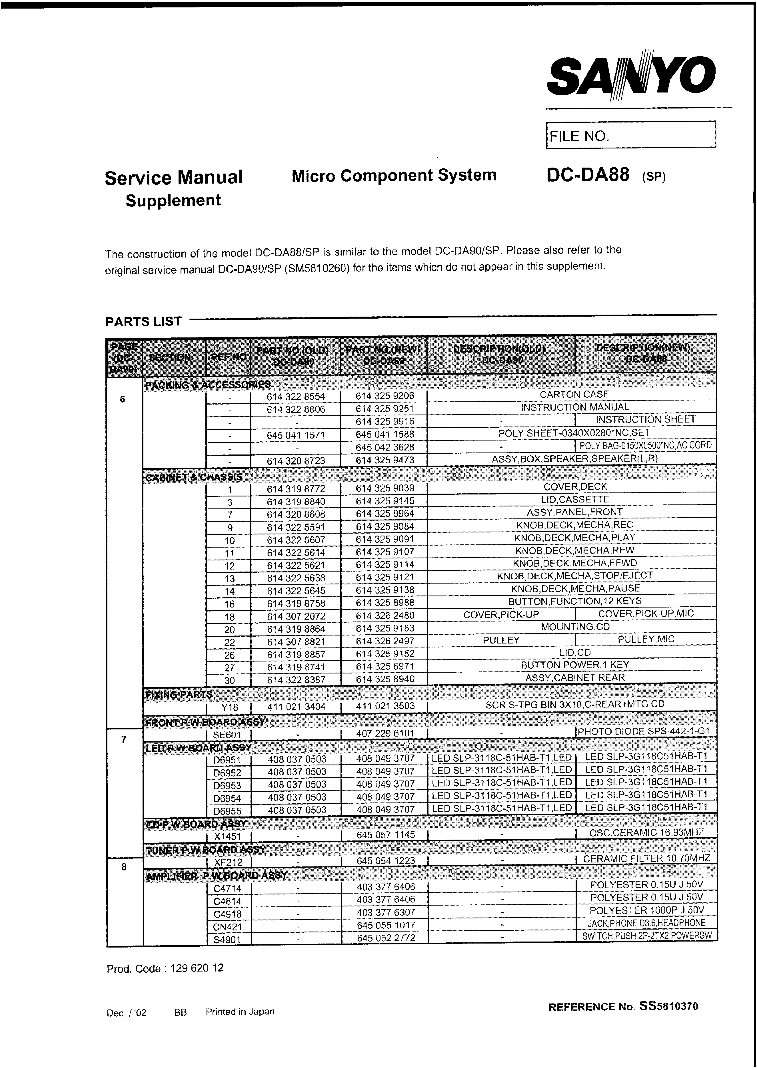
Service Manual
FILE NO.
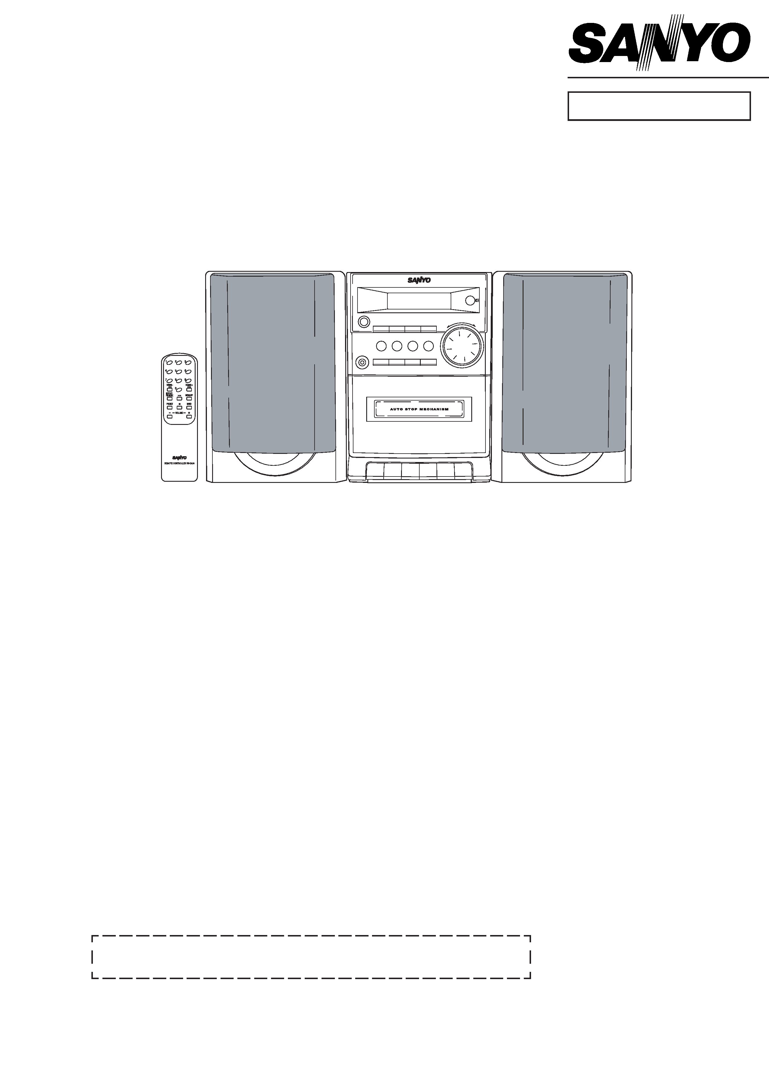
Micro Component System
DC-DA90 (SP)
PRODUCT CODE No.
129 620 02
REFERENCE No.
SM5810260
SP: This service manual consists of "DC-DA90U/SP" (Main unit : 129 619 02) and
"SX-DA90/SP" (Speaker system : 165 045 00).
Contents
Specifications ................................................................... 1
System connections ......................................................... 1
What to do if ..................................................................... 1
Laser beam safety precaution .......................................... 2
CD pick-up maintenance .................................................. 2
CD player adjustments ..................................................... 2
Tape adjustments ............................................................ 3
Tuner adjustments ........................................................... 4
Exploded view
(Cabinet & Chassis) ...................................................... 5
Parts list
(Cabinet & Chassis) ...................................................... 6
(Tape mechanism) ........................................................ 9
(CD mechanism) ........................................................... 9
IC block diagram & description ........................................ 10
LCD display description ................................................... 14
Wiring connection ............................................................ 15
Schematic diagram
(FRONT) ....................................................................... 16
(CD) ............................................................................... 18
(TUNER) ....................................................................... 22
(AMPLIFIER ) ................................................................ 26
Wiring diagram
(FRONT & CD) .............................................................. 20
(TUNER) ....................................................................... 24
(AMPLIFIER) ................................................................. 28
(POWER TRANSFORMER & LED) .............................. 30
- 1 -
SPECIFICATIONS
Tuner
Reception frequency .............. FM : 87.5 - 108.0 MHz
AM : 522 - 1611kHz
CD player
Channels ................................ 2-channel stereo
Sampling frequency ............... 44.1 kHz
Pick-up ................................... Optical 3-beam
semiconductor laser
Laser output ........................... 0.6mW(Continuous wave max.)
Wave length ........................... 790 nm
Wow and Flutter ..................... Below measurable limits
Cassette deck section
Track system ......................... 4-track, 2-channel stereo
Frequency response .............. 80 Hz - 15 kHz
Signal to noise ratio ............... 40 dB
Wow and Flutter ..................... 0.15% (WRMS)
Fast forward / Rewind time .... Approx. 110 sec. (C-60)
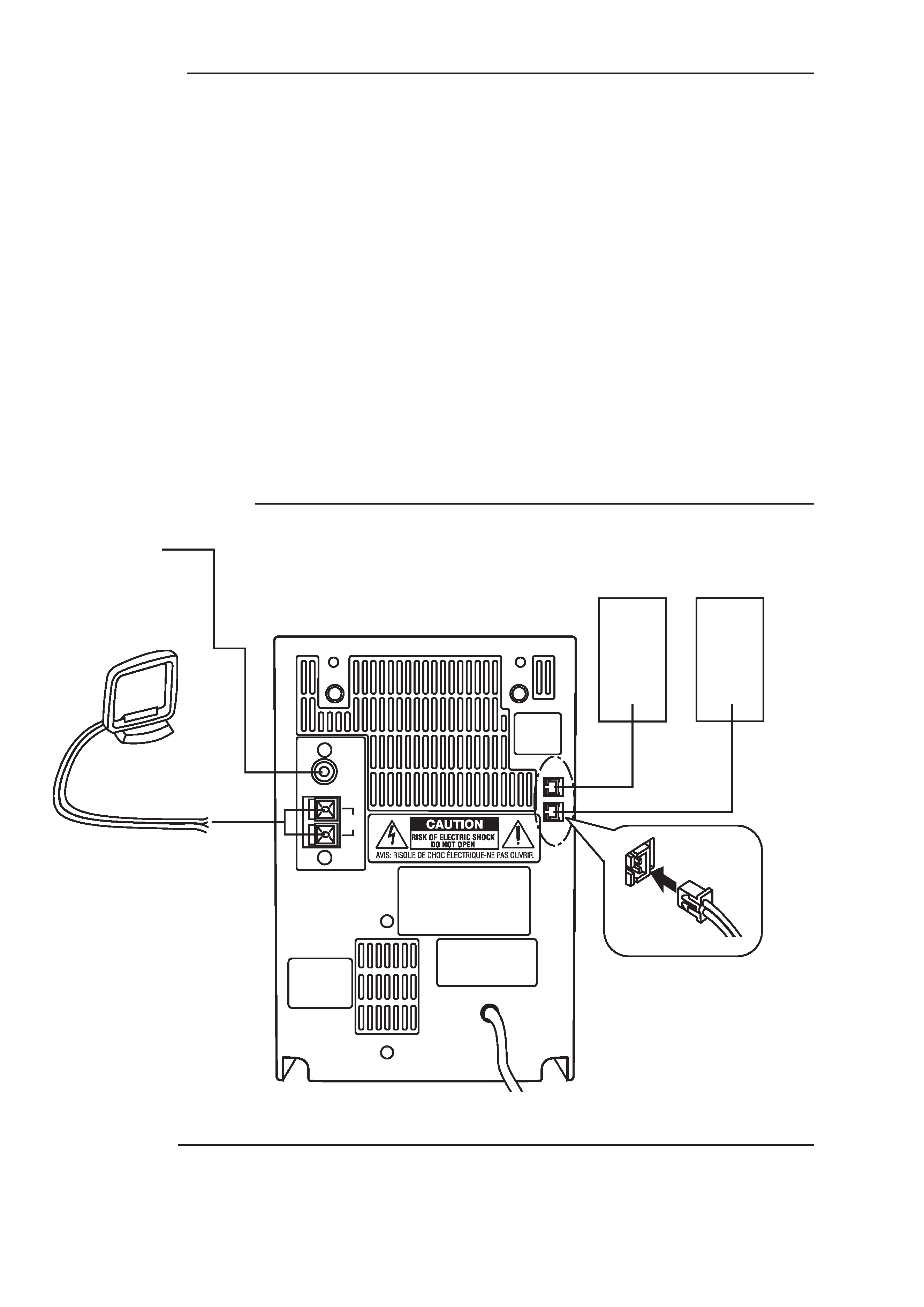
SYSTEM CONNECTIONS
FM
ANT
LOOP
AM
EXT
. ANT
L
R
SPEAKERS
4 MIN.
FM aerial
R ch speaker
L ch speaker
AM loop aerial
To an AC outlet
WHAT TO DO IF
If the operation of the unit or display is not normal,
1. Disconnect the mains lead.
2. Press the BAND button (main unit) for at least 30 seconds.
3. Connect the mains lead.
4. Operate the unit.
General
Output power ......................... 4 W x 2
(at 4 ohms, 10% distortion)
Outputs .................................. SPEAKERS : 4 ohms
PHONES : 8 - 32 ohms
Power requirements ............... AC 230V, 50Hz
Power consumption ............... 17 W
Dimensions (W x H x D) ........ Approx. 140 x 213 x 210 mm
Weight .................................... Approx. 2.1 kg
Speaker system
Type ....................................... Full range bass reflex
Unit used ................................ 8 cm cone type
Maximum
power-handling capacity ..... 6 Watts (peak)
Nominal impedance ............... 4 ohms
Dimensions (W x H x D) ........ Approx. 140 x 210 x 170 mm
Weight .................................... Approx. 1.1 kg (per speaker)
Specifications subject to change without notice.
- 2 -
LASER BEAM SAFETY PRECAUTION
· Pick-up that emits a laser beam is used in this CD player section.
CAUTION :
USE OF CONTROLS OR ADJUSTMENTS OR PERFORMANCE
OF PROCEDURES OTHER THAN THOSE SPECIFIED HEREIN
MAY RESULT IN HAZARDOUS RADIATION EXPOSURE.
THIS PRODUCT SHOULD NOT BE ADJUSTED OR REPAIRED BY
ANYONE EXCEPT PROPERLY QUALIFIED PERSONNEL.
LASER OUTPUT .............. 0.6 mW Max. (CW)
WAVELENGTH .................. 790 nm
CD PICK-UP MAINTENANCE
About pick-up (Optical lens) Cleaning
Clean a lens with swab of the cotton which moistened it with alcohol, cleaning paper or cleaning disc appointed.
Specified cleaning disc : LC-1 (Part code : 645 026 1961 ..... manufactured by SANYO.)
Show a clean procedure in the following in reference by swab of cotton.
1. Cotton swab is wrapped with Cleaning paper.
2. Add the isopropyl alcohol.
3. Gently move the tip of cotton swab just like a draw a whirlpool from inside to outside on the surface of lens.
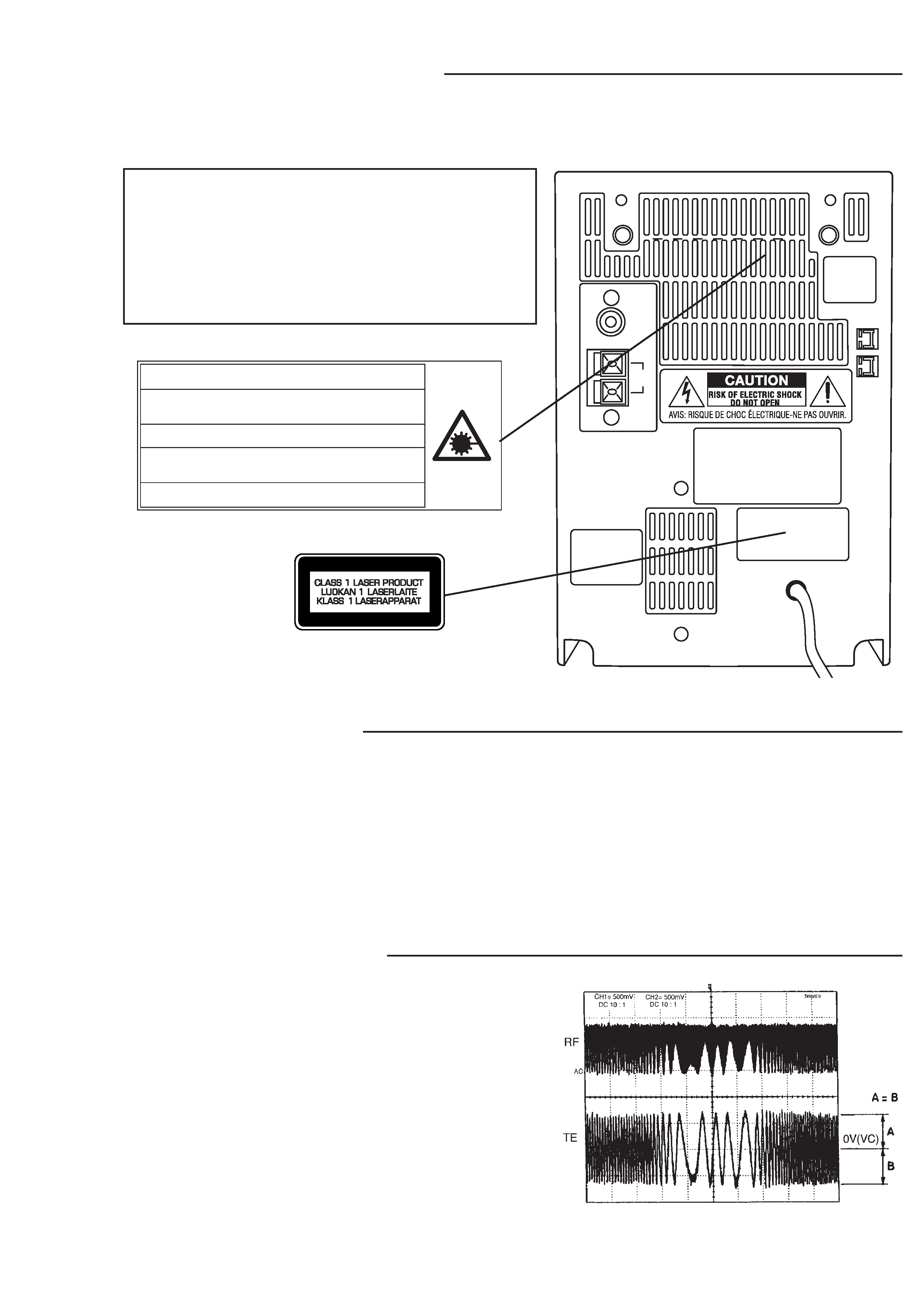
CD PLAYER ADJUSTMENTS
1. ADJUSTMENTS
(1) Confirm the tracking balance
1. Turn on the POWER switch.
2. Connect an Oscilloscope to TP2 (TE) and TP4 (VC).
3. Set the test disc.
4. Press "PLAY" button to turn into the "PLAY" mode.
5. Keep holding "SKIP" button down so as to be "SERCH"
mode, then confirm that the oscilloscope waveform is
symmetrical on the top and bottom in relation to 0V (VC).
200mV/div.
5ms/div.
FM
ANT
LOOP
AM
EXT
. ANT
L
R
SPEAKERS
4 MIN.
CAUTION INVISIBLE LASER RADIATION WHEN OPEN AND
INTERLOCKS DEFEATED. AVOID EXPOSURE TO BEAM.
ADVARSEL USYNLIG LASER STRÅLING VED ÅBNING, NÅR
SIKKERHEDSAFBRYDERE ER UDE AF FUNKTION, UNDGÅ UDS ÆTTELSE
FOR STRÅLING.
VARNING OSYNLIG LASER STRÅLNING NÄR DENNA DEL ÄR ÖPPNAD
OCH SPÄRR ÄR URKOPPLAD. STRÅLEN ÄR FARLIG.
VORSICHT UNSICHTBARE LASERSTRAHLUNG TRITT AUS, WENN
DECKEL GEÖFFNET UND WENN SICHERHEITSVERRIEGELUNG
ÜBERBRÜCKT IST. NICHT, DEM STRAHL AUSSETZEN.
VARO AVATTAESSA JA SUOJALUKITUS OHITETTAESSA OLET ALTTIINA
NÄKYMÄTTÖMÄLLE LASERSÄTEILYLLE. ÄLÄ KATSO SÄTEESEEN.
- 3 -
TAPE ADJUSTMENTS
R / P HEAD
RED
WHITE
YELLOW
EARTH
a. Replacing the head
1.
After replacement, demagnetize the heads by using
a degausser.
2.
Be sure to clean the heads before attempting to make
any adjustments.
3.
Be sure both channels (1 and 2) are the same level.
(Using a dual-channels oscilloscope).
4.
All wiring should be returned to the original position
after work is completed.
b. Adjusting head azimuth
1.
Load a test tape (VTT-738, etc. :10kHz) for
azimuth adjustment.
2.
Press the PLAY button.
3.
Use a cross-tip screwdriver to turn the screw for
normal azimuth adjustment so that the left and right
outputs are maximized at the same phase during
normal playback.
4.
Press the STOP button.
1
2
3
4
4
MOTOR SPEED
ADJUSTMENT
d.
Replacing the moto
c.
Adjusting motor speed
1. Insert the test tape (MTT-111 or etc. 3,000 Hz).
2. Press the PLAY button.
3. Use a flat-tip screwdriver to turn the SVR to adjust so
that the frequency counter becomes 3,000 Hz.
4. Press the STOP button.
e. Checking the mechanism torques
· Clean the head, capstan and pinch roller before making
any measurement.
Measurement
Take-up torque
Back tension
Tape tension
Cassette for
PLAY : TW-2111A
PLAY : TW-2111A
Drive-power cassette
measurement F.FWD/REW : TW-2231
TW-2412
PLAY
30 ~ 70gr.cm
1.0 ~ 6.0gr.cm
80 gr or more
F.FWD/REW
55 gr or more
-
-
OPENING EXPANDED
b
a
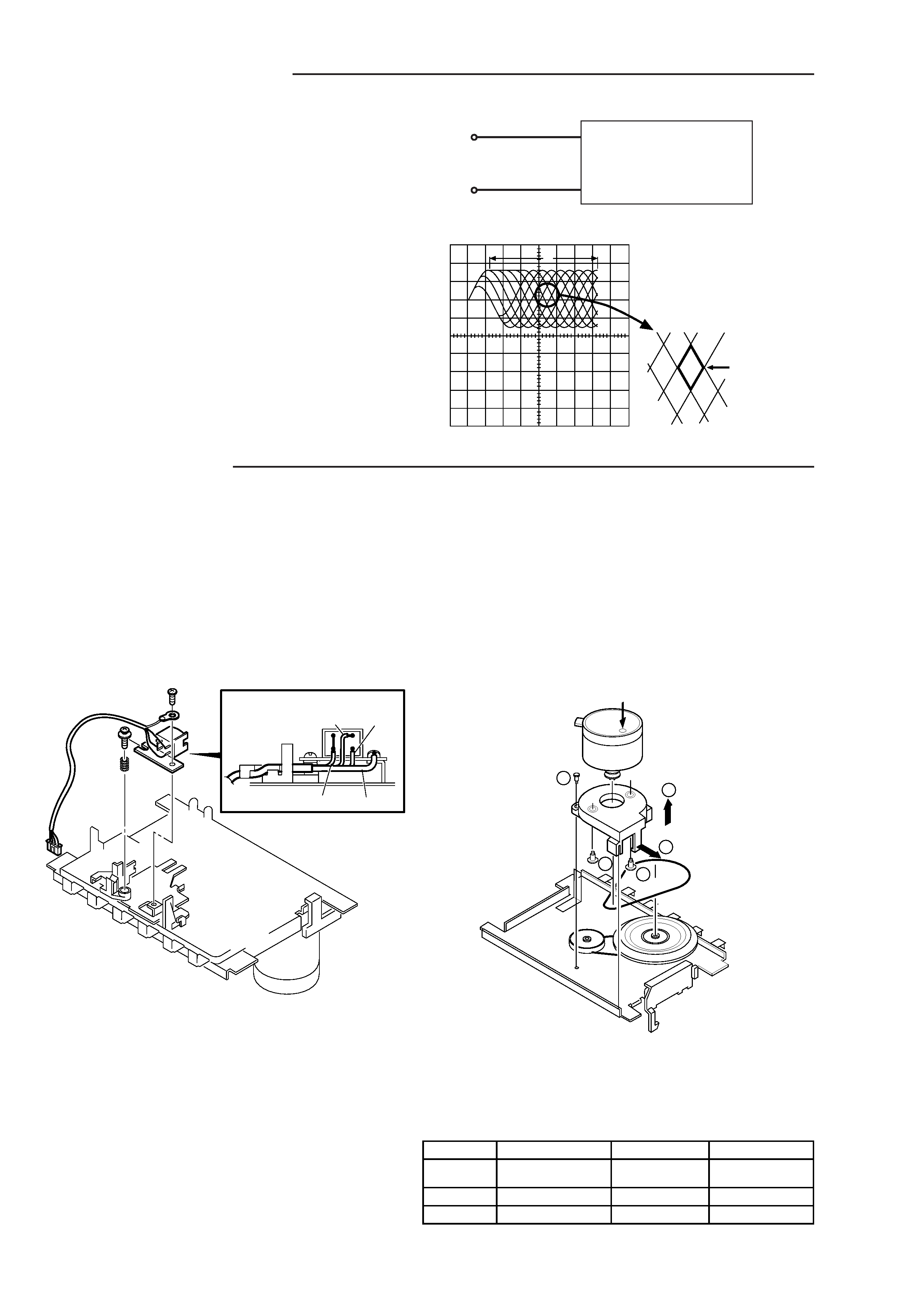
(2) Checking the "eye" pattern
1.
Switch "ON" the POWER.
2.
Connect an oscilloscope to TP1 (RF) and TP4 (VC).
3.
Load the test disc.
4.
Press the PLAY button.
5.
Check to be sure that the "eye" pattern is at
the center of waveform and that the diamond
shape is clearly defined.
6.
Press the STOP button.
7.
Turn off the POWER switch.
OSCILLOSCOPE
+
TP1
(RF)
TP4
(VC)
-
CD PLAYER ADJUSTMENTS