Part No.
SKSM0613
C3YFV
OCTOBER 2002
Colour Television
Service Manual
Model CE32WN5F-C
Service Ref. No. CE32WN5F-C-04
CE32WN5F-C-06
PRODUCT CODE: 111356910
ORIGINAL VERSION: Chassis No. EB7-A
Give complete "SERVICE REF. NO." for parts
order or servicing, it is shown on the rating sheet
on the cabinet back of the TV set.
Note
This TV receiver will not work properly in foreign
countries where the television transmission
system and power source differ from the design
specifications. Refer to the specifications for the
design specifications
CE
32WN5F-C
Contents
Safety precautions/Specifications ..................................................................................................................2
Block diagrams ..............................................................................................................................................3
Cabinet Disassembly ......................................................................................................................................4
Adjustment and Repair Procedures............................................................................................................5~9
CPU Functions ..............................................................................................................................................................................10~11
Component Locations ............................................................................................................................12~13
IC Block Diagrams ..................................................................................................................................14~18
Pin description of semiconductors ................................................................................................................19
Part Description and reading of schematic diagram ....................................................................................20
Cabinet Parts List/TV Stand parts list ..........................................................................................................21
Electric Parts List ....................................................................................................................................22~26
Please use Schematic Diagram SKP20370 with
this Service Manual.
-2-
C3YFV
SAFETY PRECAUTION
X-RADIATION PRECAUTION
The primary source of X-RADIATION in the television receiver is the picture tube. The picture tube is specially
constructed to limit X-RADIATION emissions. For continued X-RADIATION protection, the replacement tube
must be the same type as the original including suffix letter. Excessive high voltage may produce potentially
hazardous X-RADIATION. To avoid such hazards, the high voltage must be maintained within specified limit.
Refer to this service manual, high voltage adjustment for specific high voltage limit. If high voltage exceeds
specified limits, take necessary corrective action. Carefully follow the instructions for +B1 volt power supply
adjustment, and high voltage adjustment to maintain the high voltage within the specified limits.
PRODUCT SAFETY NOTICE
SPECIFICATIONS
Product safety should be considered when a component replacement is made in any area of a receiver.
Components indicated by mark
in the parts list and the schematic diagram designate components in which
safety can be of special significance. It is particularly recommended that only parts designated on the parts list in
this manual be used for component replacement designated by mark
. No deviations from resistance wattage
or voltage ratings may be made for replacement items designated by mark
.
!
!
!
1: An isolation transformer should be connected in the
power line between the receiver and the AC line
when a service is performed on the primary of the
converter transformer of the set.
2: Comply with all caution and safety-related notes
provided on the cabinet back, inside the cabinet, on
the chassis or the picture tube.
3: When replacing a chassis in the cabinet, always be
certain that all the protective devices are installed
properly, such as, control knobs, adjustment covers
or shields, barriers, isolation resistor-capacitor networks
etc. Before returning any television to the customer,
the service technician must be sure that it is completely
safe to operate without danger of electrical shock.
Power source
AC 220~240V, 50Hz
Television system
System B/G, I, L/L'
Colour system
PAL/SECAM/NTSC4.43 (PAL/NTSC4.43/MTSC3.58 INAV MODE)
Receiving channel
UHF: #21~69
Aerial input impedance
75ohm
Rear AV terminal
AV1:
CENELEC standard
INPUT:
Composite video, RGB and Audio L/R
OUTPUT:
TV-output with composite video and audio L/R
AV2:
CENELEC standard
INPUT:
Composite video, RGB, S-VHS and Audio L/R
OUTPUT:
Monitor output with composite video and Audio L/R
Front AV terminal
AV3:
RCA jacks
INPUT:
Composite video and Audio L/R
Sound output(Music)
12 x 2
Dimensions (WxHxD)
880 x 577.5 x 567mm
Weight
46.3 Kg
-3-
C3YFV
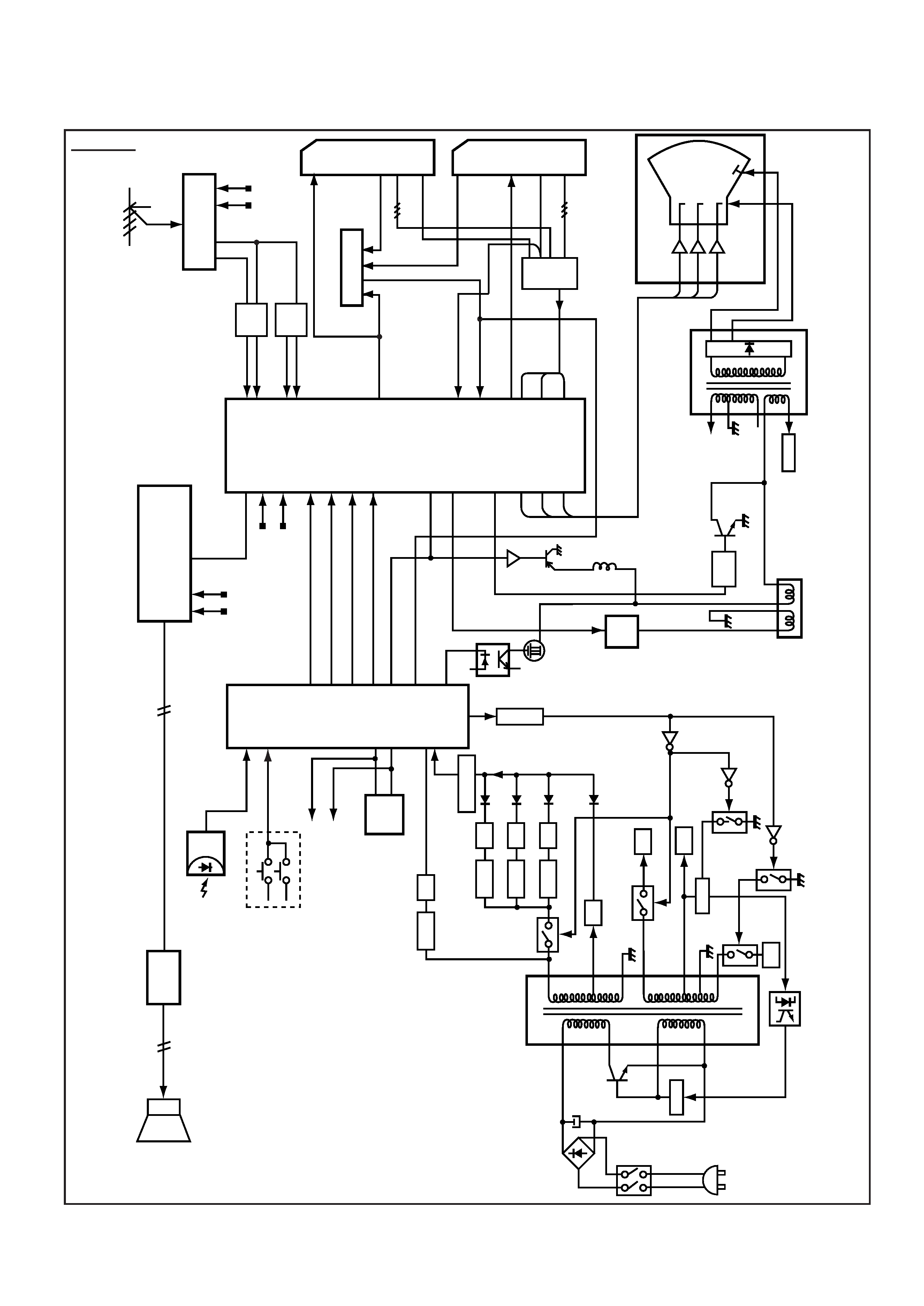
BLOCK DIAGRAM
This is a diagram for all models and therefore differs slightly from the actual block diagram.
1
5
8/10
SP902
SP901
SPEAKER
IC001
AUDIO-OUT
<TDA7263M>
IC201
IF/VIDEO/CHROMA/DEF
<TB1251>
80
79
54
26
27
20
21
22
23
IF-IN
X132
SIF-IN
A101
TUNER
IF
SCL
SDA
V
ideo-Out
SIF-OUT
K1002
SCART SC2
K1001
SCART SC1
48
46
58
61
57
56
55
R/G/B-IN
SCL
SDA
47
39
12
13
14
CR
T
HEA
TER
200V
Q701
Q71
1
Q721
B
R
G
PICTURE
TUBE
H.V
FOCUS/SCREEN
T451
FL
YBACK
R
G
B
Q431
Q432
H-OUTPUT
D.Y
V
-OUT
H-OUT
6
3
IC501
V
-OUTPUT
<LA7846>
IC1201
A
V
-VIDEO-SW
<LA7954>
IC1401 RGB-SW
<TC4053BF>
BLK
R
G
B
45
18
17
16
15
34
33
54
11
21
20
8
1
19
MUTE
IC801
CPU
IC3451
NICAM/
STEREO
RC-IN
A1901
RC
RECEIVER
KEY
-IN
KEY
SW
SDA
SCL
SDA
SCL
IC803
MEMOR
Y
PROTECT
POWER
D641
9V
IC642
D647
5V
-1
27V
IC643
Q661
Q651
Q682
Q685
25V
145V
Q641
Q686
D615
13
14
11
18
15
5
3
2
8
Q61
1
SW901
D603-D606
AC
C607
Q613
Reg.
C-IN
C-IN
Y
-IN
V
ideo/
Y
-IN
Video/Y-Out
V
ideo-IN
R/G/B-OUT
T61
1
CONVER
TER
D637
D646
5V
IC641
Q666
AERIAL
5V
12
60
61
71
98
16
1/3/13
2/5/12
4
14
15
SCL
SDA
4
5
R
G
B
51/53
M-OUT
R/G/B-IN
1
1/7/15
7/1
1/15
19
12
13
C-IN
C-OUT
15
15
53
D441
SCREEN
WIDTH
CONTROL
4
H-BLANK
L461
L462
Q461
Q462
I
2
C
BUS
CONTROL
EW
-OUT
33
X131
75
76
19
20
20
12
Q642
-27V
10
Q645
Q643
Outline
-4-
C3YFV
(A)
(A)
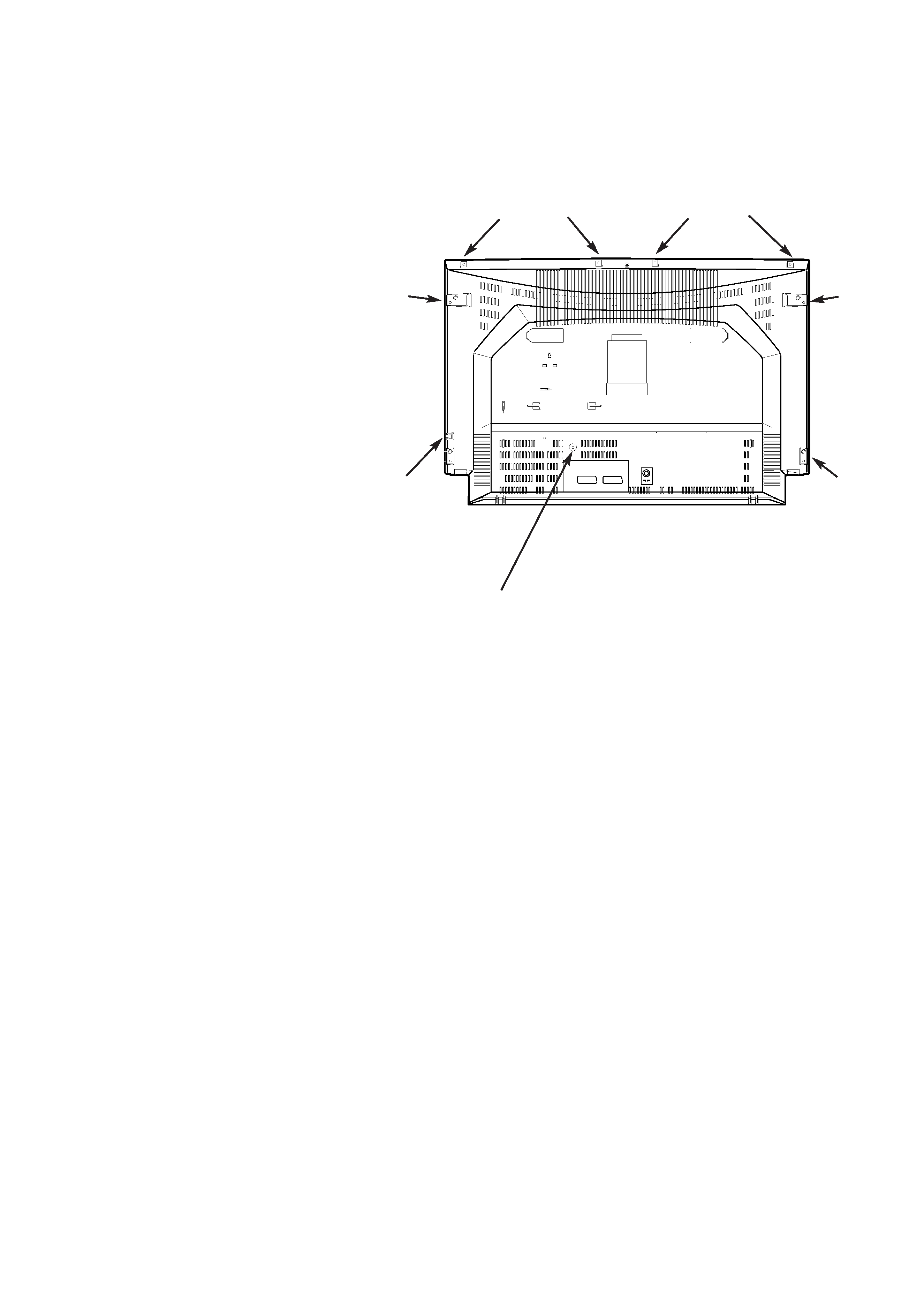
CABINET DISASSEMBLY
CABINET BACK DISASSEMBLY
1. Remove 9 screws(A) for 32"
2. Pull out the cabinet back.
(A)
(A)
(A)
(A)
(A)
(A)
(A)
ANT.75
FRONT
/DAVANTI
L/S
R/D
INT
EXT/EST
REAR
/POSTERIORE
-5-
C3YFV
Procedure for reinitialising IC803 (If replacing IC803 start at step 7)
1. Press the Normal
button on the remote control and then press the Pw button on the TV - wait for
several seconds and the channel data will disappear.
2. Switch to AV Mode (to make viewing OSD easier)
3. Press the
button.
4. Use the Pw button to highlight "otres", press the
button.
5. Use the Pw button to highlight "Idiorna del OSD", press the
until OSD language ENGLISH appears.
6. Press the
button repeatedly until the menu mode is exited.
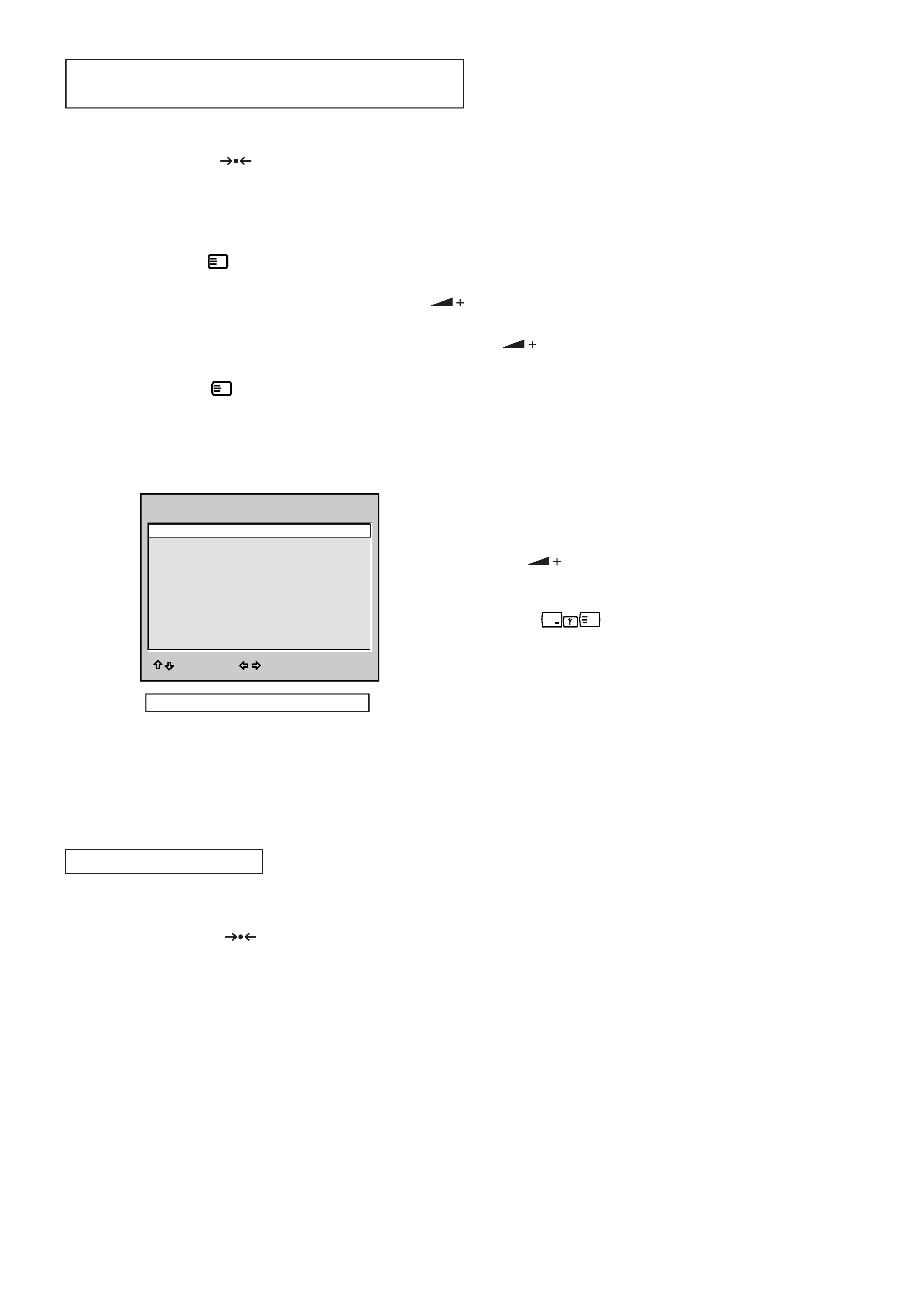
7. Reset the options menu. To select the options menu press and hold the F/OK button on the remote control
and then press the Pw button on the TV SET; the menu will appear. Set the options to match the drawing
below:
a) Press the Pw button to highlight the option you wish
to change.
b) Press the
button to match the setting in the table.
c) When all options have been set, exit the menu by pressing
the RECALL
button. The data is automatically
stored.
8. Set up the service adjustments as described on pages 6 to 9.
9. Retune all stations (see advise on page 7 for resetting Plug and Play)
Procedure for reinitialising IC803
1. Press the Normal
button on the remote control and then press the Pv button on the TV (note: if you
press the Pw follow procedure as described above instead). There is no need to set the OSD language or
alter the option table.
2. Set up the service adjustments as described on pages 6 to 9.
3. Retune all stations (see advise on page 7 for resetting Plug and Play)
?
i
MENU/
i
MENU/
REINITIALISATION OF MEMORY IC803
FOR CE32WN5F-C-04
ON-TIMER
ON
SORT MODE
SORTING
P&P
ON
WEL. TEXT
ON
COMB FILTER
OFF
BBE
OFF
AUTO VOLUME
OFF
HEADPHONE
OFF
COUNTRY
UK
WIDE
ON
OPTION
ADJUST :
EXIT : RECALL
Option settings for CE32WNF5-C-04
FOR CE32WN5F-C-06