Service Manual
CE
32WH3-F
ColourTelevision
Model CE32WH3-F
Service Ref. No. CE32WH3-F-01
PRODUCT CODE: 111340310
ORIGINAL VERSION: Chassis Series: WB5
Give complete "SERVIC E REF. NO." for parts order or
servicing. It is shown on the rating plate at the cabinet
back of the unit.
Note
This TV receiver will not work properly in foreign
countries where the television transmission
system and power source differ from the design
specification. Refer to the specifications for the
design specifications.
Contents
Safety precautions/Specifications . . . . . . . . . . . . . . . . . . . . . . . . . . . . . . . . . . . . . . . . . . . . . .
.
. . . . . .2
Block diagram . . . . . . . . . . . . . . . . . . . . . . . . . . . . . . . . . . . . . . . . . . . . . . . . . . . . . . . . .. . . . . . . . . .3-5
Digital scan operation . . . . . . . . . . . . . . . . . . . . . . . . . . . . . . . . . . . . . . . . . . . . . . . . . . .
.
. . . . . . . . .6-8
Power supply & protection diagram . . . . . . . . . . . . . . . . . . . . . . . . . . . . . . . . . . . . . . . . . . . . . .
.
. . . . .9
Disassembly . . . . . . . . . . . . . . . . . . . . . . . . . . . . . . . . . . . . . . . . . . . . . . . . . . . . . . . . . .. . . . . . . . . . .10
Option setting . . . . . . . . . . . . . . . . . . . . . . . . . . . . . . . . . . . . . . . . . . . . . . . . . . . . . . . .. . . . . . . . . . . .11
Service adjustments . . . . . . . . . . . . . . . . . . . . . . . . . . . . . . . . . . . . . . . . . . . . . . . . . . . . .
.
. . . . . .12-15
CPU port functions . . . . . . . . . . . . . . . . . . . . . . . . . . . . . . . . . . . . . . . . . . . . . . . . . . . . .
.. . . . . . .16-18
IC block diagrams . . . . . . . . . . . . . . . . . . . . . . . . . . . . . . . . . . . . . . . . . . . . . . . . . . . . . . .. . . . . . .19-27
Waveforms . . . . . . . . . . . . . . . . . . . . . . . . . . . . . . . . . . . . . . . . . . . . . . . . . . . . . . . . . . .. . . . . . . .28-31
Pin description of semi-conductors . . . . . . . . . . . . . . . . . . . . . . . . . . . . . . . . . . . . . . . . . . . . .
.
. . . . .32
Parts description and reading in schematic diagram . . . . . . . . . . . . . . . . . . . . . . . . . . . . . . . . . . . . .
.3
3
Cabinet parts List/T V Stand parts list . . . . . . . . . . . . . . . . . . . . . . . . . . . . . . . . . . . . . . . . . . . . .
. .34-36
Chassis electrical parts lists . . . . . . . . . . . . . . . . . . . . . . . . . . . . . . . . . . . . . . . . . . . . . . .
.
. . . . . .37-60
Part No. SKSM0325
F7YLV
SEPT 1999
F7YLV
1: An isolation transformer should be connected in the
power line between the receiver and the AC line
when a service is performed on the primary of the
converter transformer of the set.
2: Comply with all caution and safety-related notes
provided on the cabinet back, inside the cabinet, on
the chassis or the picture tube.
3: When replacing a chassis in the cabinet, always be
certain that all the protective devices are installed
properly, such as, control knobs, adjustment covers
or shields, barriers, isolation resistor-capacitor
networks etc. Before returning any television to the
customer, the service technician must be sure that
it is completely safe to operate without danger of
electrical shock.
-2-
SAFETY PRECAUTION
X-RADIATION PRECAUTION
The primary source of X-RADIATION in the television receiver is the picture tube. The picture tube is specially
constructed to limit X-RADIATION emissions. For continued X-RADIATION protection, the replacement tube must
be the same type as the original including suffix letter. Excessive high voltage may produce potentially hazardous
X-RADIATION. To avoid such hazards, the high voltage must be maintained within specified limit. Refer to this
service manual, high voltage adjustment for specific high voltage limit. If high voltage exceeds specified limits,
take necessary corrective action. Carefully follow the instructions for +B1 volt power supply adjustment, and high
voltage adjustment to maintain the high voltage within the specified limits.
PRODUCT SAFETY NOTICE
SPECIFICATIONS
Product safety should be considered when a component replacement is made in any area of a receiver.
Components indicated by mark
in the parts list and the schematic diagram designate components in which
safety can be of special significance. It is particularly recommended that only parts designated on the parts list in
this manual be used for component replacement designated by mark
. No deviations from resistance wattage or
voltage ratings may be made for replacement items designated by mark
.
!
!
!
Power source
AC 220~240V, 50Hz
Television system
System B/G, D/K, I, L/L'
Colour system
PAL/SECAM/NTSC4.43 on air
NTSC3.58 in AV mode
Channel coverage
VHF: E2-E12, A-H, H1, H2, F2-F10, R1-R12
UHF: 21-69, F21-F69
CATV: X, Y, Z, Z+1, Z+2, S1-S41, B-Q
Aerial input impedance
75ohm
AV terminal
21-pin terminals
AV1: CENELEC Standard with RGB
AV2: CENELEC Standard with S-inputs
AV3: CENELEC Standard
Front AV terminals
AV3: RCA Terminal, Video and Audio(L/R) Input
Sound output Main L/R
10.0 x 2
(Continuous)(watts)
Picture tubes(inches)
32
Dimensions(WxHxD mm)
876 x 584 x 556
Weight (kg)
50kg
-3-
F7YLV
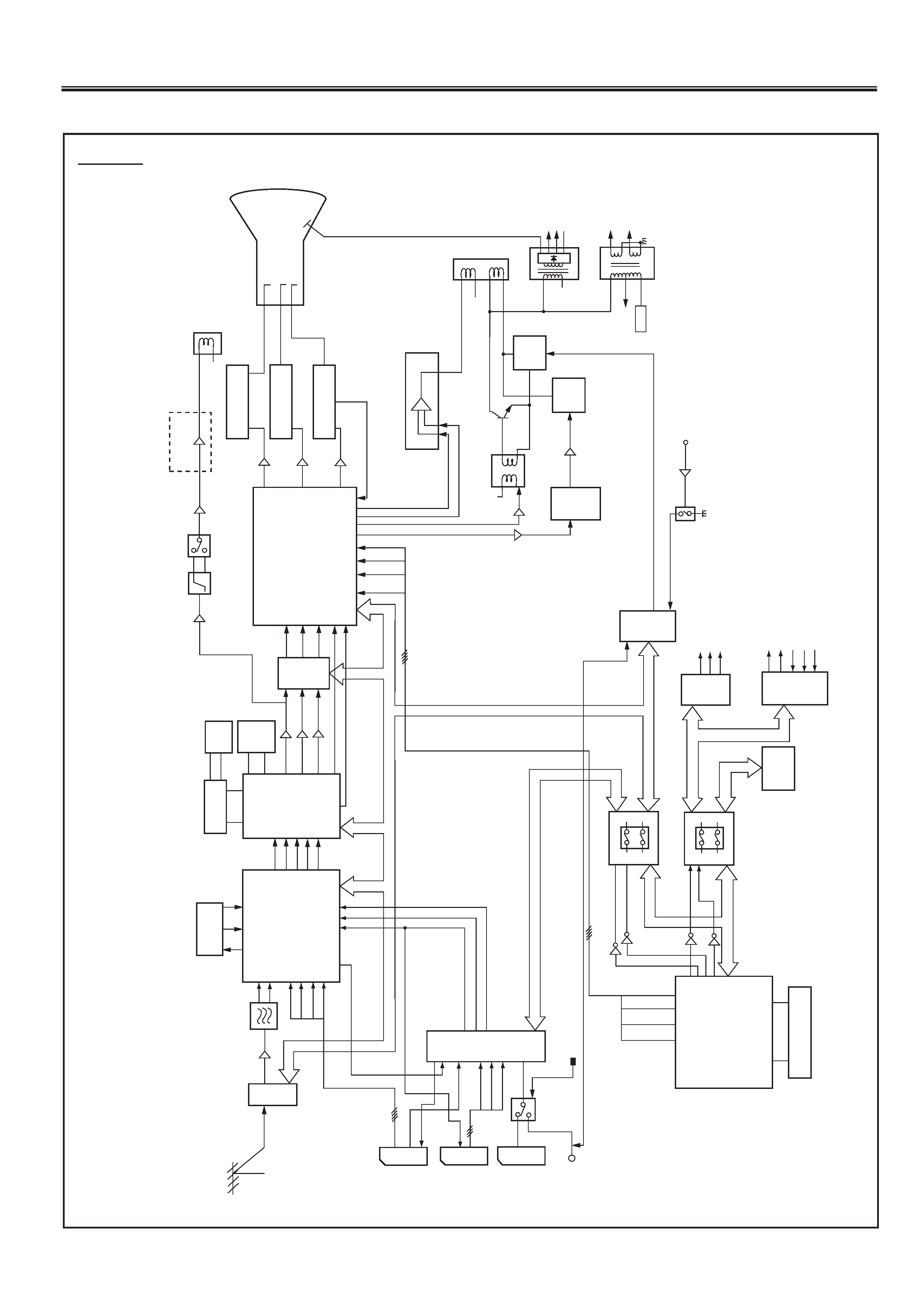
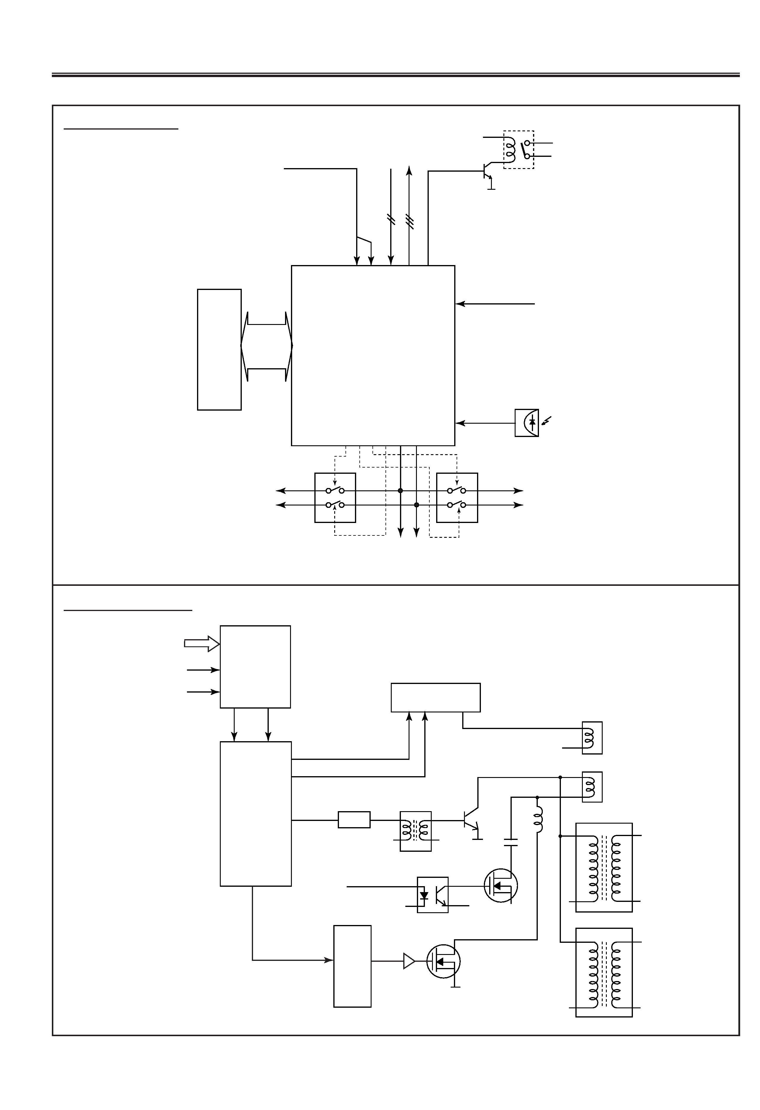
This is a diagram for all models and therefore differs slightly from the actual block diagram.
ROM
47
46
45
44
19
20
21
22
23
24
12/6
13/5
9
10
8
2
4
11
12/6
13/5
9
10
8
2
4
11
IC804
MC14066
BUS
SW
15
14
15
14
11
10
7
6
5
15
14
4
1
12
11
10
2
IC808
PCF8574
IC807
PCF8574
MUTE
ON/OFF
A
V3/FRONT
A
V4
SW
3D
SURROUND
ON/OFF
3L-Y/C
SEP
ON/OFF
P
AL/NTSC
SW
A
V3
SW
A
V2
SW
A
V1
SW
I/O
EXP
ANDEDER
SCAR
T1
AV
1
SCAR
T2
AV
2
SCAR
T3
AV
3
FRONT
AV
4
MONIT
OR-
OUT
SC1
V
-IN
23
41
1
7
9
11
27
34
37
39
19
20
8
9
6
7
SC2
V
-IN
SC2
Y
-IN
SC2
C-IN
IC1201
MM1313BD
TV
-OUT
R/G/B/BLK
IC1
181
NJM2284
SCL/SDA
IF/VIDEO/
CHROMA/
MARTIX
2
3
36
37
38
39
34
18
20
21
47
61
60
51
50
49
29
28
26
46
CVBS-OUT
Y
-OUT
C-OUT
CVBS-2-IN
R
G
B
BLK
IF
4
5
Aerial
T
uner
X132
SAF
Q131
IC7101
CXD2064
3L-Y/C
SEP
V
YC
26
28
30
22
20
1
71
72
74
76
79
A/D
D/A
CONVERTER
Y
U
V
HD
VD
SCAN
CONVERTER
IC7250
SAA4991
IC101
TDA9321
FIELD
MEMOR
Y
IC7206
SAA4955
FIELD
MEMOR
Y
6
8
9
11
14
16
17
19
2Y
-OUT
2U-OUT
2V
-OUT
IC201
TDA9178
Q7341
Q7305
Q7309
MA
TRIX
DEFLECTION
IC202
TDA9330
28
27
26
23
24
8
44
46
41
42
38
37
36
35
3
10
11
SDA/SCL
SCL/SDA
IC801
ST9212915
CPU
RG
B
BLK
OSD
BG
R
BLK
IC71
1
TDA61
1
1
IC721
TDA61
1
1
IC731
1
TDA61
1
1
B
VIDEO-OUT
G
VIDEO-OUT
R
VIDEO-OUT
35
8
3
5
8
3
5
8
G
B
R
CR
T
IC501
LA7846
1
2
H-DRIVE
E-W
Q402
T401A
H-DRIVE
IC471
MB3759
IK
Q237
Q236
Q235
G
R
B
V
DRIVE
-
V
DIR
VE+
15
8
PCC
CONTROL
CS
CONTROL
H-OUTPUT
Q41
1
POWER
ERROR
Q1803
Q1904
CS-SW
IC809
CXA1315
Q473
140V
FOCUS
SCREEM
T402
CHOKE
TRANS
T402
FL
YBACK
65V
HEA
TER
200V
V
H
D.Y
VERT
OUTPUT
6
5
3
VM
CIRCUIT
VM
COIL
Q307
IC301
L302
Q301
Y
U
V
VD
HD
AV
SELECT
OR
FRONT
A
V4/A
V3
SW
IC803
FRONT
A
V
-IN
SCL/SDA
IC806
MC14066
BUS
SW
SCL/SDA
Q801
Q803
Q804
Q802
I
2
C
BUS
2V
-OUT
2H-OUT
MEMOR
Y
65
SCL/SDA
SCL/SDA
Q366/
Q378
2
9
7
TV
-OUT
IC7207
SAA4955
H.V
IC802
M27C1001
2
+
_
Outline
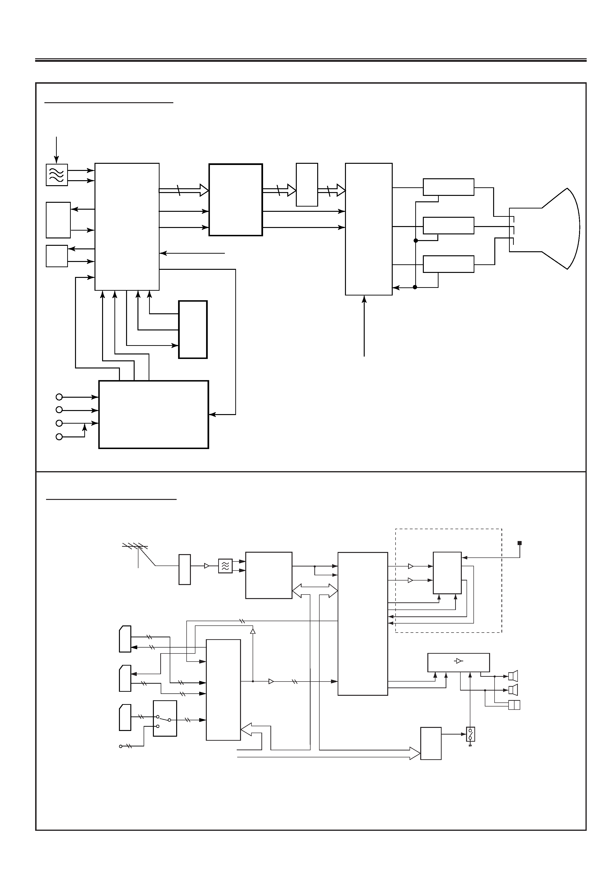
CHASSIS BLOCK DIAGRAMS
Fig.-1
-4-
F7YLV
IC101
IF/VIDEO/
CHROMA
<TDA9321H>
IC202
CTI
<TDA9330H>
IC201
SHARPNESS
<TDA9178>
DIGITAL
SCAN
CONVERTER
CIRCUIT
3L
Y/C
SEP
.
AV
SELECTOR
CIRCUIT
SIF
Filtering
circuit
Buffer
2
3
10
12
13
14
18
20
21 26
28 29
34
36
|
38
61
60
23
40
41
42
38
35
24
49
50
51
6
8
9
19
17
16
26
27
28
Y, U, V
2(Y, U, V)
H-Sync
V-Sync
2HD
2VD
External RGB in
SAW Filter
IF Stage
Video-in
C-in
C-in
Y
-in
Y-in
Y-out
AV1
AV2
AV3
AV4
3
5
8
IC731
R-VIDEO OUT
<TDA6111Q>
3
5
8
IC721
G-VIDEO OUT
<TDA6111Q>
3
5
8
IC711
B-VIDEO OUT
<TDA6111Q>
R
G
B
IK
RGB OSD
DISPLAY from CPU
Picture Tube
Video signal routeing
SCART1
AV1
SCART2
AV2
SCART2
AV3
FRONT
AV4
1,4
16,11
3
5
L/R
SC3-IN
IC1201
MM1313
22,24
42
40
2
4
8
10
25
26
33
32
IC3501
MM1369
3D
SURROUND
PROCESSOR
3D SUPPER
L
SPEAKER
R
SPEAKER
HEADPHONE
JACK
Q001
IC807
PCF8574
IC3451
TDA9875
Q3453
Q3452
L
R
23
1
10
9
13
11
6
48
47
20
9
33
34
IC002
TA8200
AUDIO
AMP
7
11
12
24
12
14
15
MUTE
12
29
51
52
32
31
60
61
IC101
TDA9321
SCL/SDA
SCL/SDA
NICAM&
SOUND
CONTROLLER
L/R
TV-OUT
MONITOR
OUT
SC1-IN
SC2-IN
L/R
IC1181
NJM2284
Q1215
Q1217
Q1223
Q1224
FROM
CPU
L/R
TV-IN
SIF
MONO
Tuner
Q131
X131
SAF
Aerial
L
R
L
R
L/R
L/R
5
63
44
IF/VIDEO/
CHROMA
63
44
5
IF/VIDEO/
CHROMA
+
I
2
C BUS
AV
SELECTOR
19
20
I/O
EXPANDER
ACTIVE 3D SURROUND PROCESSING
Audio signal routeing
Fig.-2
Fig.-3
-5-
F7YLV
IC801
CPU
IC802
ROM
CVBS input
Q1652
RL1601
Power
Supply
Circuit
OSD
RGB
Dr
iv
e
H-Sync
V
-Sync
1
|
5
63
|
80
61
60
48 49 44-47 42
38
25
RC Pre-amp.
IC804
Bus-SW.
IC806
Bus-SW.
I2C Bus
SDA/SCL
I2C Bus
SDA/SCL-1
MEMORY
I2C Bus
SDA/SCL-2
SDA/SCL-3
19 20 21 22
23
24
Photo
Sensor
Power ON/OFF
DIGITAL
SCAN
CONVERTER
CS SW.
IC421
H-Drive
Q401-Q402
T401
Drive Trans
Q411
H-Output
IC501
V-Output <LA786>
56
3
V-Drive +
V-Drive -
Q421
3
8
2
1
23
24
EW-Out
3
15
8
11
IC471
<MB3759P>
Q472
Q473
Vert.
Coil
Horiz.
Coil
Deflection
Yoke
T402
FlyBack Trans.
T403
Choke
Trans.
L461/L462
C421
Pcc Control
IC202
DEFLECTION
<TDA9330H>
2H-Sync
2V-Sync
Screen Width Control
Y.U.V
H-SYNC
V-SYNC
System control
Deflection circuit
Fig.-4
Fig.-5