Part No.
SKSM0554
C2KYV
MAY 2002
Colour Television
Service Manual
Model CE21DN7-C
Service Ref. No. CE21DN7-C-00
PRODUCT CODE: 111351118
ORIGINAL VERSION: Chassis No. EB6-B
Give complete "SERVICE REF. NO." for parts
order or servicing, it is shown on the rating sheet
on the cabinet back of the TV set.
Note
This TV receiver will not work properly in foreign
countries where the television transmission
system and power source differ from the design
specifications. Refer to the specifications for the
design specifications
CE
21DN7-C
Contents
Safety precautions/Specifications ......................................................................................................2
Block diagrams ..............................................................................................................................3~5
Cabinet Disassembly ..........................................................................................................................6
Adjustment and Repair Procedures..............................................................................................7~11
CPU Functions ..............................................................................................................................................................12~13
Component Locations ................................................................................................................14~15
IC Block Diagrams......................................................................................................................16~18
Pin description of semiconductors....................................................................................................19
Part Description and reading of schematic diagram ........................................................................20
Cabinet Parts List/TV Stand parts list ..............................................................................................21
Electric Parts List........................................................................................................................22~29
Please use Schematic Diagram SKP20345 with
this service manual.
-2-
C2KYV
SAFETY PRECAUTION
X-RADIATION PRECAUTION
The primary source of X-RADIATION in the television receiver is the picture tube. The picture tube is specially
constructed to limit X-RADIATION emissions. For continued X-RADIATION protection, the replacement tube
must be the same type as the original including suffix letter. Excessive high voltage may produce potentially
hazardous X-RADIATION. To avoid such hazards, the high voltage must be maintained within specified limit.
Refer to this service manual, high voltage adjustment for specific high voltage limit. If high voltage exceeds
specified limits, take necessary corrective action. Carefully follow the instructions for +B1 volt power supply
adjustment, and high voltage adjustment to maintain the high voltage within the specified limits.
PRODUCT SAFETY NOTICE
SPECIFICATIONS
Product safety should be considered when a component replacement is made in any area of a receiver.
Components indicated by mark
in the parts list and the schematic diagram designate components in which
safety can be of special significance. It is particularly recommended that only parts designated on the parts list in
this manual be used for component replacement designated by mark
. No deviations from resistance wattage
or voltage ratings may be made for replacement items designated by mark
.
!
!
!
1: An isolation transformer should be connected in the
power line between the receiver and the AC line
when a service is performed on the primary of the
converter transformer of the set.
2: Comply with all caution and safety-related notes
provided on the cabinet back, inside the cabinet, on
the chassis or the picture tube.
3: When replacing a chassis in the cabinet, always be
certain that all the protective devices are installed
properly, such as, control knobs, adjustment covers
or shields, barriers, isolation resistor-capacitor networks
etc. Before returning any television to the customer,
the service technician must be sure that it is completely
safe to operate without danger of electrical shock.
Power source
AC 220~240V, 50Hz
Television system
System B/G, D/K
Colour system
PAL/NTSC4.43 (PAL/NTSC4.43/MTSC3.58 IN AV MODE)
Receiving channel
UHF: 21~69
VHF: E2-E12, R1-R12
CATV: X, Y, Z, S1-S41
Aerial input impedance
75ohm
AV terminal
21 Pin SCART Terminal
AV1:CENELEC standard with RGB
AV2:CENELEC standard with S-inputs
Front AV
AV3:RCA Terminal, Video and Audio (L/R)
Sound output(Music)
8W x 2
Dimensions (WxHxD)
612 x 476 x 482mm
Weight
21 Kg
-3-
C2KYV
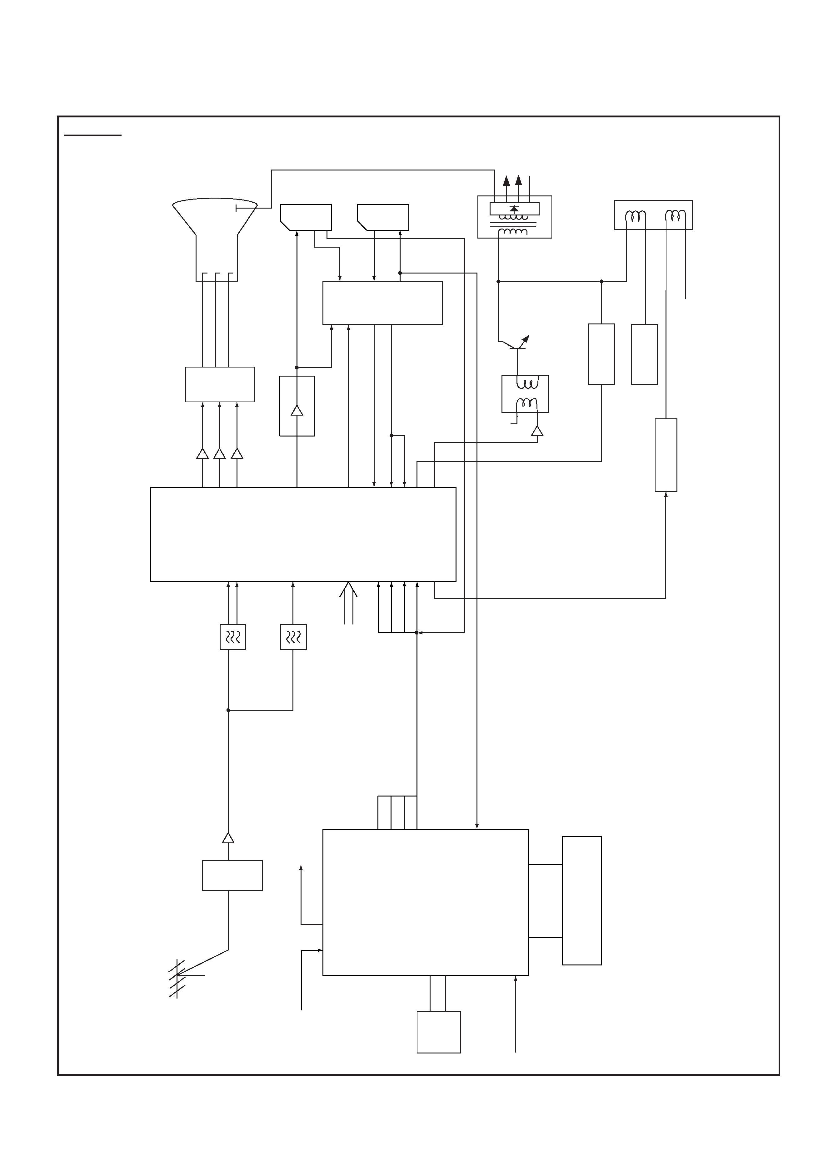
BLOCK DIAGRAM
This is a diagram for all models and therefore differs slightly from the actual block diagram.
IC801
CPU
IC803
MEMOR
Y
SCL
SD
A
IC802
RO
M
IC201
IF/VIDEO/
CHR
OMA/
DEF
Q242
Q243
Q244
Q701
Q711
Q721
VIDEO-OUT
CR
T
R
G
B
R
G
B
Q121~Q133
TV
-OUT
SIF-IN
C-OUT
Y
-OUT
13
8
15
18
AV
1
AV
2
TV
-IN
SC-1
SC-2
MONT
O
-OUT
X132
X131
VIF
SIF
6
7
9
34
35
15
16
17
18
26
T451
FBT
H
V
D.
Y
PCC
CONTR
OL
CS
CONTR
OL
Q432
Q431
H-OUT
EW
-OUT
43
39
40
41
32
3
54
22
21
20
V
-OUT
IC501
3
6
C
Y
SYNC-IN
BLK
R
G
B
I
2 C
B
U
S
BLK
B
G
R
CVBS-IN
61
60
47
46
45
44
25
26
24
23
19
1
-
15
80
-
63
T431
PR
O
TECT
-IN
PC-IN
PO
WER
Q141
A101
TUNER
Aer
ial
FOCUS
SCREEN
Ref
er
also
to
FIG.-2.
A
V
SELECT
OR
NICAM
DECODER
Outline
-4-
C2KYV
FROM KH
K12H
AV3
OUT
Q1202
AV3-L
SC2
Q1207
AV3-R
SC1
KJ
K12J
Y-OUT
TV IN
Q1203
BA
Q3453
SC2 C-IN
SC1 L IN
SC1 L IN
SC1 R-IN
Q1202
SC1 RIN
L-OUT
SC1 L-OUT
SC2 RIN
Q3452
SC2 R-IN
R-OUT
Q1206
SC2 L-IN
SC2 LIN
SC1 R-OUT
MOL
AV3-R IN
AV3-L IN
TV/VIDEO IN
MOR
Q3454
Y-OUT
Q3455
SDA
KM
SCL
SIF IN
SIF IN
C-OUT
L-OUT TO IC001
CTRL A FROM IC801
S-SW FROM IC801
R-OUT TO IC001
FROM MAIN K1101
CTRL B FROM IC801
SC1 VIDEO IN
SC2 VIDEO IN
SCART 2 VIDEO OUT
SC2 L-OUT
SC2 R-OUT
AV3 VIDEO IN
IC1202 NJM2233BD
IC3451 TDA9875A/V2
IC1203 HD14052BP
IC1201 LA7952
4
1
8
6
9
6
3
8
12
13
15
11
3
4
5
9
10
7
10
5
14
15
2
11
37
36
51
52
4
5
1
3
5
13
20
18
10
11
8
4
15
6
1
3
5
3
2
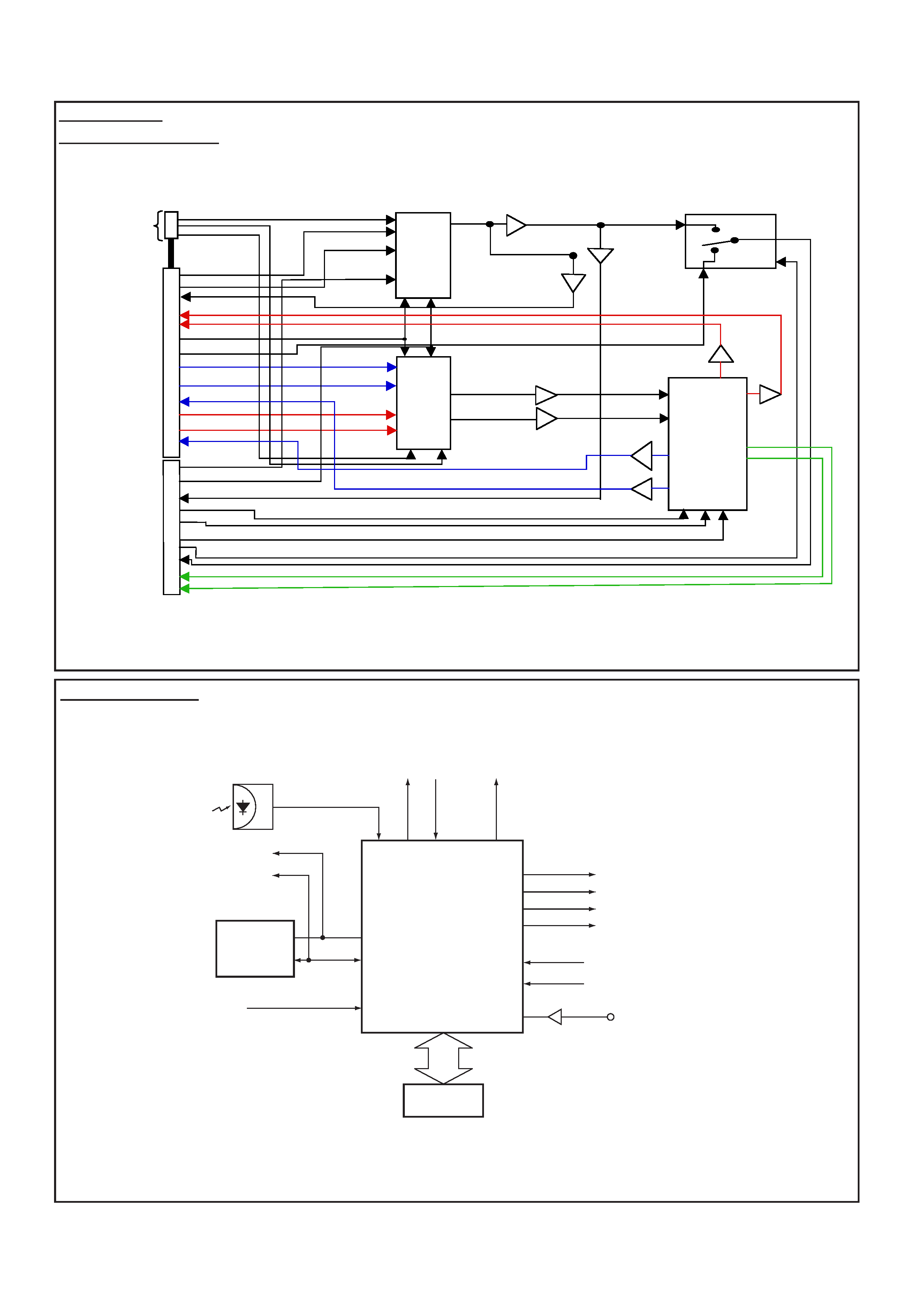
K12M
AV Selector
NICAM DECODER
IC801
CPU
25
31
28
24
23
43
61
60
36
46
45
44
1 - 7, 63 - 80
PO
WER
39
Rela
y
SW
KEY
-IN
37
SC1(AV1) 8-pin
SC2(AV2) 8-pin
RC-IN
BLK-OUT
B-OUT
G-OUT
R-OUT
Q806
CVBS
POWER-FAIL
DETECT
SCL
SDA
IC803
MEMORY
I
2C BUS
CONTROL
IC802
ROM
System Control
Fig.-2
Fig.-3
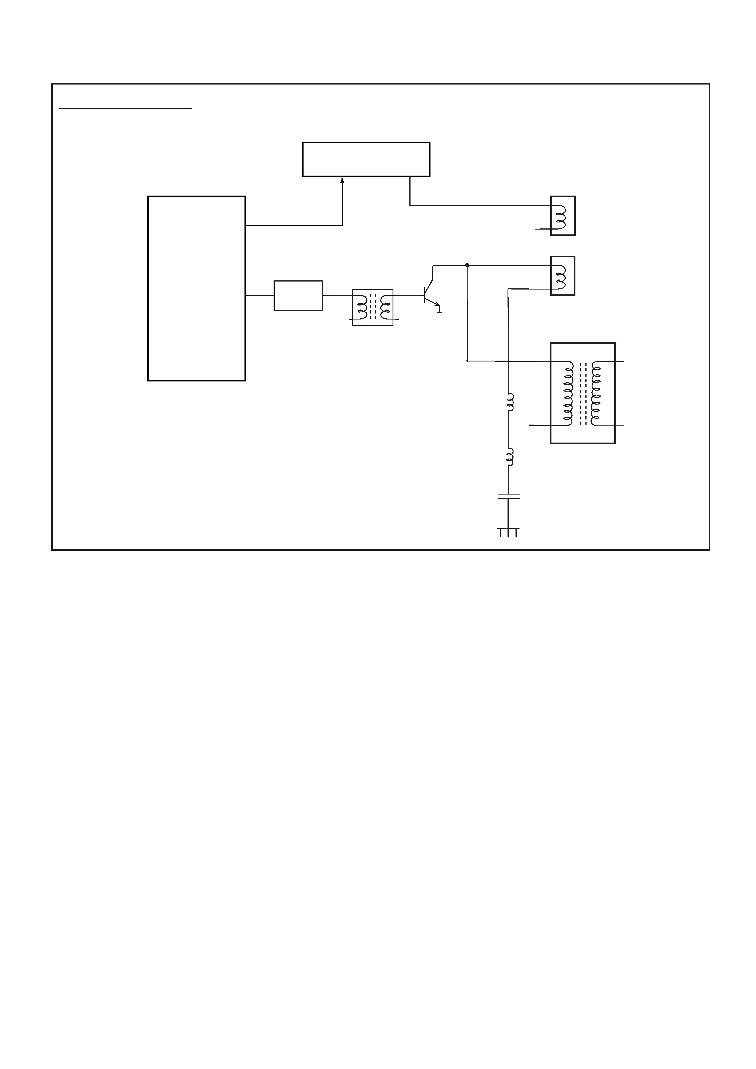
-5-
C2KYV
IC201
IF/VIDEO/
DEFLECTION
<TB1251>
26
41
32
V-Drive
H-Drive
Q431
IC501
V-Output<LA7832>
63
Deflection
Yoke
Horiz.
Coil
Vert.
Coil
T451
FlyBack Trans
T431
Q431
H-Output
Drive Trans
L441
C441
L442
Deflection Control