Indice
1.
Safety instructions............................................................................................................................................ 1
2.
WARNING........................................................................................................................................................ 1
3.
Precaution against X-Rays............................................................................................................................... 1
4.
Recommendations to protect our environment................................................................................................ 1
5.
TECHNICAL CHARATERISTICS. ................................................................................................................... 2
6.
Safety ............................................................................................................................................................... 2
7.
EMC (Electromagnetic Compatibility) .............................................................................................................. 2
8.
CONNECTED DOCUMENTS. ......................................................................................................................... 3
9.
MOUNTED CIRCUITS CODES. ...................................................................................................................... 3
10.
ABBREVIATIONS USED IN THE PARTS LIST AND CABINET PARTS LIST. ........................................... 3
11.
CABINET PARTS LIST ................................................................................................................................ 4
11.1.
CABINET PARTS LIST OF CHASSIS CE21AT2-C AND CE21AT2-E................................................. 4
11.2.
CABINET PARTS LIST OF CE21AT2-C AND CE21AT2-E ................................................................. 5
12.
PARTS LIST ................................................................................................................................................. 6
CE21AT2-C
CE21AT2-E
Service Manual
Models:
CRT 14" Philips A51EAL155X10
CHASSIS 2113
EC7-B
Colour Television
Give complete "SERVICE PART No" for parts order or
servicing, it is shown on the rating sheet on the cabinet
back of the TV set.
Note
This TV receiver will not work properly in foreign countries
where the television transmission system and power
source differ from the design specifications. Refer to the
specifications for the design specifications.
Ref. Nº MS CE21AT2-C
02-01-2001
Service Manual SM CE21AT2-C
1
1. Safety instructions
Read this page before doing any operation of adjustment, maintenance or repair the TV set described.
Only skilled personnel of Sanyo Technical Service should do the adjustment, maintenance or repair of TV set.
2. WARNING
For the correct and safe use of the TV set, it is essential that the service personnel follow the process of safety
generally accepted and the safety precautions specified in this manual.
An isolation transformer should be connected in the power line between the receiver and the AC line when a service
is performed on the primary side of the converter transformer of the set.
3. Precaution against X-Rays
The primary source of X-RADIATION in the television receiver is the picture tube. The picture tube is specially
constructed to limit X-RADIATION emissions. For continued X-RADIATION protection, the replacement tube must
be the same type as the original including suffix letter. Excessive high voltage may produce potentially hazardous X-
RADIATION. To avoid such hazards, the high voltage must be maintained within specified limit. If high voltage
exceeds specified limits, take necessary corrective action. Follow the instructions carefully for +B1 volt power supply
adjustment, and high voltage adjustment to maintain the high voltage within the specified limits.
COMPLIANCE TO STANDARDS
All of those marked with
! or
must be
replaced with original parts
WARNING! This TV set contains components which
are particularly sensitive to static electricity (ESD).
It is recommended that all due precaution be taken
handling integrated circuits and semiconductors.
4. Recommendations to protect our environment
Stand-by mode: In order to save energy and to maintain an optimum picture quality, it is advisable to switch off the
TV using the ON/OFF button located at the front of TV set.
Used batteries: The batteries in the remote control of these models do not contain mercury. However, SANYO
recommends that you do not dispose of used batteries in domestic refuse. Please, contact your dealer or your local
authorities for information regarding the disposal of used batteries or your nearest collection point.
Recommendation about the end-of-life: These SANYO TV sets have been designed and manufactured using high
quality materials which can be recycled and reused. In the future, when the life cycle of these sets come to an end,
specialised companies can disassemble it and reuse certain materials. This reduces the impact of waste in our
environment. Please, contact with your local authorities for information regarding the disposal of your set when the
time arrives. Help us to conserve the environment we live in!
Service Manual SM CE21AT2-C
2
5. TECHNICAL CHARATERISTICS.
Cathode-ray tubes
In-Line, gun Type. Black Matrix. 21" (54 cm)
Tuning-system
Voltage synthesis, 100 programs in non-volatile memory, AFT, Fine-tuning (10 first
programs), automatic, semiautomatic and manual channel-search.
Band I, channels 2-4 (VHF)=E2-E4
Cable channels S1-S20
Hyperband channels S21-S41
Band III, channels 5-12 (VHF)=E5-E12
Band IV-V, channels 21-69 (UHF)=E21-E69
Reception system
B/G Model CE21AT2-C
B/G-D/K Model CE21AT2-E
Colour system
PAL, NTSC 4.43, N.A.P. (NTSC Amusement by PAL)
Program selection
Sequential selection from the controls on the set. Direct selection to any program
from the remote-control device.
Audio
Power-rating 3,2W rms. (10% distortion)
Speakers
1 of 8
.
Aerial
External aerial sockets 75 ohms. IEC
Jack for headphones
Mono jack 3,5mm.
Clock and alarm Function
Timer Function
Switch on and off of CTV programmable in real time.
AV connectors
1 Scart connector 21 pin CENELEC standard AV, RGB and S_Video.
1 RCA Video input (frontal)
1 RCA Audio input (frontal)
Power supply
220 240 VAC 50Hz
Consumption
48 W (IEC 107-1)
3,5 W (Stand-by
)
Text
1.5 FLOF and LIST level. 1 page memory.
Radio
87.5 108MHz. 40 memories. Manual and semiautomatic search
Hotel mode
Hotel mode and Hotel Rental
Options by means of Technical Service:
SECAM, NTSC-M
6. Safety
It fulfils the safety requirements established in the regulation:
· EN 60065:93
7. EMC (Electromagnetic Compatibility)
It fulfils the EMC requirements established in the regulation:
· EN 55013:1990/A12:1994
· EN 55020:1994
· EN 60555-2:1987
Service Manual SM CE21AT2-C
3
8. CONNECTED DOCUMENTS.
This Service Manual provides the particular information of the models CE21AT2-C and CE21AT2-E and it is
complemented with:
1.
Service Manual of the CHASIS 2113 (EC7-B).
2.
Service Electrical scheme of the model CE21AT2-C.
3.
Instruction manual.
9. MOUNTED CIRCUITS CODES.
CE21AT2-C
CE21AT2-E
6110377600
6110379705
Main + Socket TRC PCB's
7110019309
7110019606
Main PCB
7040003605
7040003605
Socket TRC PCB
10. ABBREVIATIONS USED IN THE PARTS LIST AND CABINET PARTS LIST.
Note : The following abbreviations indicate:
C
Exclusive parts for
CE21AT2-C
E
Exclusive parts for
CE21AT2-E
Service Manual SM CE21AT2-C
4
11. CABINET PARTS LIST
11.1. CABINET PARTS LIST OF CHASSIS CE21AT2-C AND CE21AT2-E
Ref. No.
Part No.
Description
YG4
"
0080112907 Comp. side IF shield EC7-A
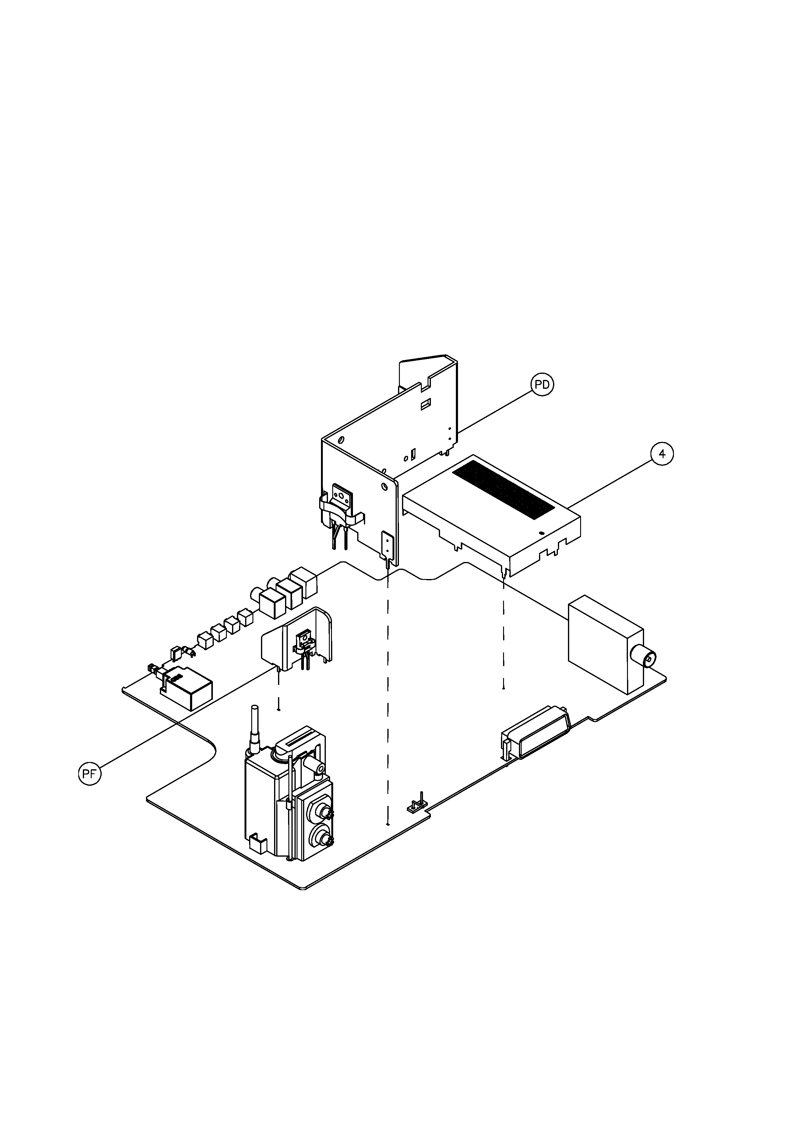
Assy PD (Deflection)
IC701
0360516306 LA7841L
Q650
0360306708 S 2055 N
YR701
0200225605 Heatsink Deflection EC7-B
YR702
0010106300 Spring CLIP 56379
YR703
0010106300 Spring CLIP 56379
Assy PF(Power supply)
Q800
0360310809 MOS 2SK2750 600V/3,5A
YR800
0200225506 Heatsink Source EC7-A
YR801
0010110401 Spring CLIP 56363