- 1 -
SERVICE MANUAL
AE-6D CHASSIS
MODEL
COMMANDER
DEST
CHASSIS NO.
KD-32NX200U
RM-939
UK
SCC-Q84L-A
KD-32NX200U
RM-939

- 2 -
TABLE OF CONTENTS
Section
Title
Page
Section
Title
Page
Caution
....................
3
Specifications
....................
4
Connectors
....................
5
Self Diagnostic Software
....................
6
1. GENERAL
Automatically Tuning the TV
....................
9
Using a digital text service
....................
9
Using a conventional text service ................
10
The EPG menu
....................
10
Using the TV menu system
....................
11
Viewing memory stick pictures ....................
12
Remote Control operation of
VCR and DVD player
...............
13
Specifications
....................
14
Troubleshooting
....................
14
2. DISASSEMBLY
2-1.
Rear Cover Removal
....................
15
2-2.
Speaker Box Removal
....................
15
2-3.
Chassis Removal and Refitting ....................
15
2-4.
G1 Board Removal
....................
16
2-5.
G Board Removal
....................
16
2-6.
D2 Board Removal
....................
16
2-7.
D1 Board Removal
....................
16
2-8.
Service Position
....................
17
2-9.
Wire Dressing 1
....................
17
2-10.
Wire Dressing 2
....................
17
2-11.
Wire Dressing 3
....................
17
2-12.
Picture Tube Removal
....................
18
Bottom Plates
....................
19
3. SET-UP ADJUSTMENTS
3-1.
Beam Landing
....................
20
3-2.
Convergence
....................
21
3-3.
Focus Adjustment
....................
23
3-4.
Screen (G2), White Balance
....................
23
4. CIRCUIT ADJUSTMENTS
4-1.
Electrical Adjustments
....................
24
4-2.
Volume Electrical Adjustments ....................
28
4-3.
Test Mode 2
....................
29
CAUTION
SHORT CIRCUIT THE ANODE OF THE PICTURE TUBE AND THE
ANODE CAP TO THE METAL CHASSIS, CRT SHIELD, OR THE
CARBON PAINTED ON THE CRT, AFTER REMOVAL OF THE
ANODE CAP.
WARNING !!
AN ISOLATION TRANSFORMER SHOULD BE USED DURING
ANY SERVICE WORK TO AVOID POSSIBLE SHOCK HAZARD
DUE TO LIVE CHASSIS, THE CHASSIS OF THIS RECEIVER IS
DIRECTLY CONNECTED TO THE POWER LINE.
SAFETY-RELATED COMPONENT WARNING !!
COMPONENTS IDENTIFIED BY SHADING AND MARKED
ON
THE SCHEMATIC DIAGRAMS, EXPLODED VIEWS AND IN THE
PARTS LIST ARE CRITICAL FOR SAFE OPERATION. REPLACE
THESE COMPONENTS WITH SONY PARTS WHOSE PART
NUMBERS APPEAR AS SHOWN IN THIS MANUAL OR IN
SUPPLEMENTS PUBLISHED BY SONY.
ATTENTION
APRES AVOIR DECONNECTE LE CAP DE'LANODE,
COURT-CIRCUITER L'ANODE DU TUBE CATHODIQUE ET
CELUI DE L'ANODE DU CAP AU CHASSIS METALLIQUE DE
L'APPAREIL, OU AU COUCHE DE CARBONE PEINTE SUR LE
TUBE CATHODIQUE OU AU BLINDAGE DU TUBE
CATHODIQUE.
ATTENTION !!
AFIN D'EVITER TOUT RISQUE D'ELECTROCUTION
PROVENANT D'UN CHÁSSIS SOUS TENTION, UN
TRANSFORMATEUR D'ISOLEMENT DOIT ETRE UTILISÈ LORS
DE TOUT DÈPANNAGE LE CHÁSSIS DE CE RÈCEPTEUR EST
DIRECTMENT RACCORDÈ Á L'ALIMENTATION SECTEUR.
ATTENTION AUX COMPOSANTS RELATIFS Á
LA SECURITÈ!!
LES COMPOSANTS IDENTIFIÈS PAR UNE TRAME ET PAR UNE
MARQUE
SUR LES SCHÈMAS DE PRINCIPE, LES VUES
EXPLOSÈES ET LES LISTES DE PIECES SONT D'UNE IMPOR-
TANCE CRITIQUE POUR LA SÈCURITÈ DU FONCTIONNEMENT,
NE LES REMPLACER QUE PAR DES COMPSANTS SONY DONT
LE NUMÈRO DE PIÈCE EST INDIQUÈ DANS LE PRÈSENT
MANUEL OU DANS DES SUPPLÈMENTS PUBLIÈS PAR SONY.
5. DIAGRAMS
5-1.
Block Diagrams (1)
....................
31
Block Diagrams (2)
....................
32
Block Diagrams (3)
....................
33
Block Diagrams (4)
....................
34
Block Diagrams (5)
....................
35
5-2.
Circuit Board Location
....................
35
5-3.
Schematic Diagrams and
Printed Wiring Boards
....................
35
* A Board PWB
....................
36
* A Board Schematic ....................
39
* B5 Board PWB
.................
48
* B5 Board Schematic ....................
49
* C1 Board PWB
....................
57
* C1 Board Schematic ....................
58
* H Board PWB
....................
57
* H Board Schematic ....................
59
* MS2 Board PWB
....................
57
* MS2 Board Schematic ..............
59
* D1 Board PWB
....................
60
* D1 Board Schematic ....................
61
* G1 Board PWB
....................
63
* G1 Board Schematic ....................
62
* D2 Board PWB
....................
63
* D2 Board Schematic ....................
64
* M2 Board PWB
....................
65
* M2 Board Schematic ....................
66
* G Board PWB
....................
68
* G Board Schematic
...................
67
* VM Board PWB
.................
68
* VM Board Schematic ................
69
* F3 Board PWB
....................
70
* F3 Board Schematic ....................
69
* H3 Board PWB
....................
70
* H3 Board Schematic ....................
71
* J3 Board PWB
....................
70
* J3 Board Schematic ....................
72
5-4.
Semiconductors
....................
74
5-5.
IC Blocks
....................
76
6. EXPLODED VIEWS
6-1.
Chassis
....................
79
6-2.
Picture Tube
....................
80
7. ELECTRICAL PARTS LIST
....................
81
- 3 -
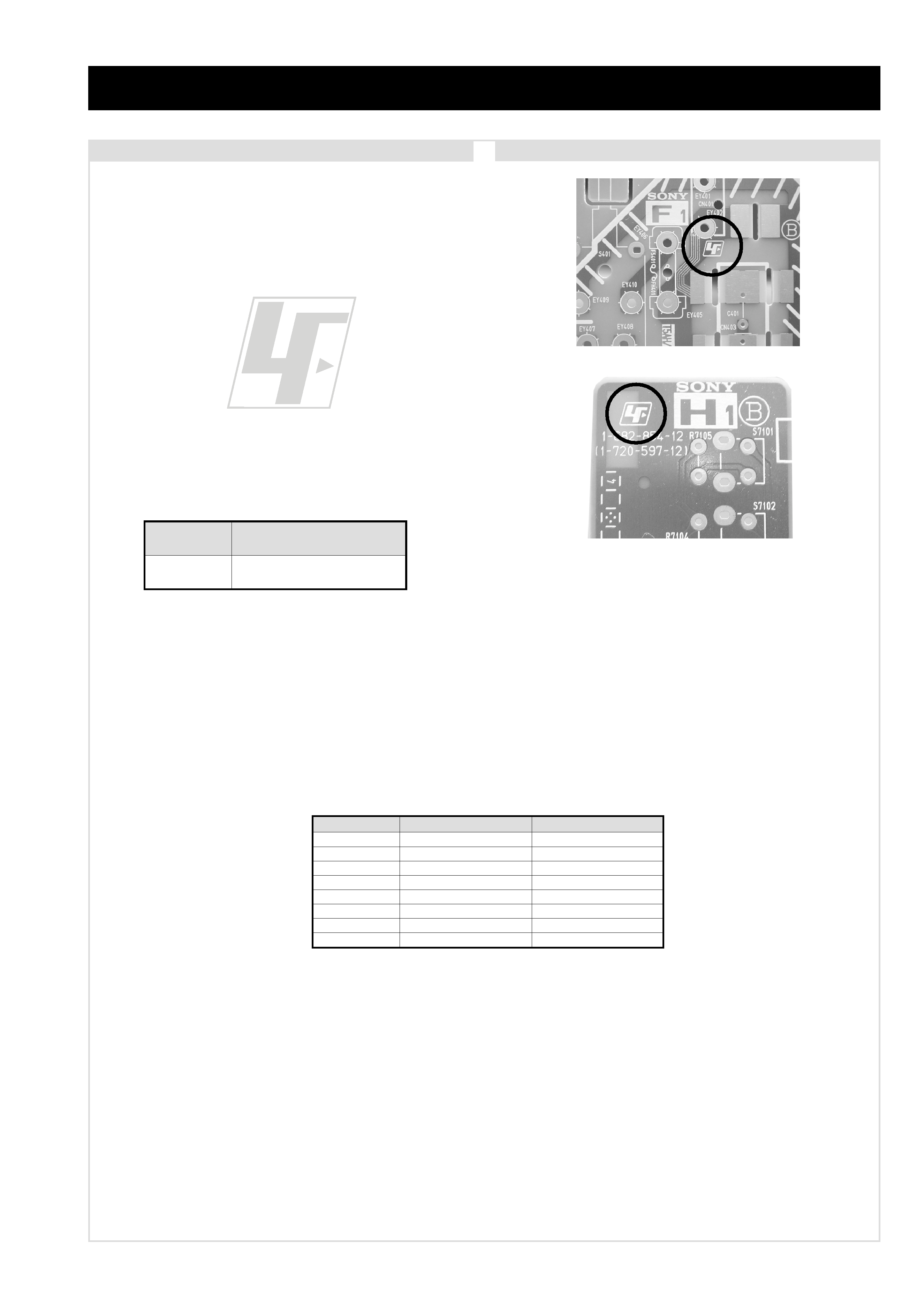
The circuit boards listed below [Table 1] used in these models may
have been processed using Lead Free Solder. The boards are
identified by the LF logo located close to the board designation e.g.
F1, H1 etc [ see examples ]. The servicing of these boards requires
special precautions to be taken as outlined below.
Table 1
CAUTION
Lead Free Soldered Boards
example 1
example 2
It is strongly recommended to use Lead Free Solder material in order to guarantee optimal quality of new solder joints. Lead Free Solder is
available under the following part numbers :
Due to the higher melting point of Lead Free Solder the soldering iron tip temperature needs to be set to 370 degrees centigrade. This requires
soldering equipment capable of accurate temperature control coupled with a good heat recovery characteristics.
For more information on the use of Lead Free Solder, please refer to http://www.sony-training.com
r
e
b
m
u
n
t
r
a
P
r
e
t
e
m
a
i
D
s
k
r
a
m
e
R
9
1
-
5
0
0
-
0
4
6
-
7m
m
3
.
0g
K
5
2
.
0
0
2
-
5
0
0
-
0
4
6
-
7m
m
4
.
0g
K
0
5
.
0
1
2
-
5
0
0
-
0
4
6
-
7m
m
5
.
0g
K
0
5
.
0
2
2
-
5
0
0
-
0
4
6
-
7m
m
6
.
0g
K
5
2
.
0
3
2
-
5
0
0
-
0
4
6
-
7m
m
8
.
0g
K
0
0
.
1
4
2
-
5
0
0
-
0
4
6
-
7m
m
0
.
1g
K
0
0
.
1
5
2
-
5
0
0
-
0
4
6
-
7m
m
2
.
1g
K
0
0
.
1
6
2
-
5
0
0
-
0
4
6
-
7m
m
6
.
1g
K
0
0
.
1
d
r
a
o
B
n
o
i
t
c
n
u
F
3
H
d
n
a
e
n
o
h
p
d
a
e
H
,
t
u
p
n
I
V
A
t
n
o
r
F
s
e
h
c
t
i
w
S
l
o
r
t
n
o
C
- 4 -
L
E
D
O
M
M
E
T
I
m
e
t
s
y
S
n
o
i
s
i
v
e
l
e
T
m
e
t
s
y
S
o
e
r
e
t
S
e
g
a
r
e
v
o
C
l
e
n
n
a
h
C
m
e
t
s
y
S
r
o
l
o
C
UT
-
B
V
D
,
I
M
A
C
I
N
o
e
r
e
t
S
9
6
B
-
1
2
B
:
F
H
U
,
8
5
.
3
C
S
T
N
,
L
A
P
)
N
I
O
E
D
I
V
(
3
4
.
4
C
S
T
N
L
M
@
P
M
,
2
-
G
E
P
M
How to replace the fuse.
Open the fuse compartment with
a screwdriver blade and replace
the fuse.
FUSE
e
b
u
T
e
r
u
t
c
i
P
n
o
r
t
i
n
i
r
T
D
F
)
s
e
h
c
n
i
2
3
(
m
c
2
8
x
o
r
p
p
A
d
e
r
u
s
a
e
m
e
r
u
t
c
i
p
m
c
6
7
x
o
r
p
p
A
(
)
y
ll
a
n
o
g
a
i
d
n
o
i
t
c
e
l
f
e
d
e
e
r
g
e
d
°
2
0
1
t
u
p
t
u
O
d
n
u
o
S
r
e
k
a
e
p
s
t
f
e
L
d
n
a
t
h
g
i
R
r
e
f
o
o
w
b
u
S
)
S
M
R
(
W
0
1
x
2
)
r
e
w
o
P
c
i
s
u
M
(
W
0
2
x
2
)
S
M
R
(
W
5
1
x
1
)
r
e
w
o
P
c
i
s
u
M
(
W
0
3
x
1
]
R
A
E
R
[
s
l
a
n
i
m
r
e
T
t
u
p
t
u
O
/
t
u
p
n
I
s
n
o
i
t
a
c
i
f
i
c
e
p
S
l
a
r
e
n
e
G
r
o
t
c
e
n
n
o
c
o
r
u
E
n
i
p
-
1
2
:
1
)
d
r
a
d
n
a
t
s
C
E
L
E
N
E
C
(
.
s
l
a
n
g
i
s
o
e
d
i
V
d
n
a
o
i
d
u
A
r
o
f
s
t
u
p
n
I
.
B
G
R
r
o
f
s
t
u
p
n
I
o
i
d
u
A
d
n
a
o
e
d
i
V
V
T
f
o
s
t
u
p
t
u
O
.
s
l
a
n
g
i
s
s
t
n
e
m
e
r
i
u
q
e
R
r
e
w
o
PV
0
4
2
-
0
2
2
n
o
i
t
p
m
u
s
n
o
C
r
e
w
o
PW
4
5
1
r
o
t
c
e
n
n
o
c
o
r
u
E
n
i
p
-
1
2
:
2
.
s
l
a
n
g
i
s
o
e
d
i
V
d
n
a
o
i
d
u
A
r
o
f
s
t
u
p
n
I
.
B
G
R
r
o
f
s
t
u
p
n
I
o
i
d
u
A
d
n
a
o
e
d
i
V
V
T
f
o
s
t
u
p
t
u
O
.
s
l
a
n
g
i
s
s
n
o
i
s
n
e
m
i
Dm
m
0
9
5
x
5
.
5
4
4
x
0
1
9
x
o
r
p
p
A
t
h
g
i
e
Wg
k
7
6
x
o
r
p
p
A
r
o
t
c
e
n
n
o
c
o
r
u
E
n
i
p
-
1
2
:
3
.
s
l
a
n
g
i
s
o
e
d
i
V
d
n
a
o
i
d
u
A
r
o
f
s
t
u
p
n
I
.
o
e
d
i
V
S
r
o
f
s
t
u
p
n
I
s
l
a
n
g
i
s
o
i
d
u
A
d
n
a
o
e
d
i
V
r
o
f
s
t
u
p
t
u
O
)
e
l
b
a
t
c
e
l
e
s
(
s
e
i
r
o
s
s
e
c
c
A
d
e
il
p
p
u
S
r
e
d
n
a
m
m
o
C
e
t
o
m
e
R
9
3
9
-
M
R
)
2
(
y
r
e
t
t
a
b
6
R
d
e
t
a
n
g
i
s
e
d
C
E
I
e
l
b
a
c
h
g
u
o
r
h
t
p
o
o
L
F
R
s
k
c
a
J
o
n
o
h
P
o
i
d
u
A
r
o
f
e
l
b
a
i
r
a
v
s
r
o
t
c
e
n
n
o
C
t
u
p
t
u
O
s
l
a
n
g
i
S
t
e
k
c
o
S
A
I
C
M
C
P
e
l
u
d
o
M
s
s
e
c
c
A
l
a
n
o
i
t
i
d
n
o
C
s
e
r
u
t
a
e
F
r
e
h
t
O
t
x
e
t
e
l
e
T
e
g
a
P
0
0
0
2
,
P
O
H
,
R
N
D
,
F
C
D
,
F
M
C
R
D
E
B
B
,
y
b
l
o
D
l
a
u
t
r
i
V
,
y
r
o
m
e
M
]
T
N
O
R
F
[
s
l
a
n
i
m
r
e
T
t
u
p
t
u
O
/
t
u
p
n
I
l
o
r
t
n
o
c
d
e
r
a
r
f
n
I
:
m
e
t
s
y
s
l
o
r
t
n
o
c
e
t
o
m
e
R
k
c
a
j
e
n
o
h
p
d
a
e
Hk
c
a
j
i
n
i
m
o
e
r
e
t
s
s
t
n
e
m
e
r
i
u
q
e
r
r
e
w
o
P
c
d
V
3
n
o
i
t
a
n
g
i
s
e
d
C
E
I
s
e
i
r
e
t
t
a
b
2
)
A
A
e
z
i
s
(
6
R
s
t
u
p
n
i
o
i
d
u
As
k
c
a
j
o
n
o
h
p
s
t
u
p
n
i
o
e
d
i
Vs
k
c
a
j
o
n
o
h
p
t
u
p
n
i
o
e
d
i
V
SN
I
D
n
i
p
4
.
e
c
i
t
o
n
t
u
o
h
t
i
w
e
g
n
a
h
c
o
t
t
c
e
j
b
u
s
e
r
a
s
n
o
i
t
a
c
i
f
i
c
e
p
s
d
n
a
n
g
i
s
e
D
e
m
a
N
l
e
d
o
M
m
e
t
I
U
0
0
2
X
N
2
3
-
D
K
P
A
PF
F
O
P
I
PF
F
O
y
t
i
r
o
i
r
P
B
G
RN
O
x
o
B
r
e
f
o
o
WN
O
1
t
r
a
c
SN
O
2
t
r
a
c
SN
O
)
4
(
n
i
t
n
o
r
FN
O
3
t
r
a
c
SN
O
r
o
t
c
e
j
o
r
PF
F
O
G
/
B
m
r
o
NF
F
O
I
m
r
o
NN
O
K
/
D
m
r
o
NF
F
O
S
U
A
m
r
o
NF
F
O
L
m
r
o
NF
F
O
T
A
S
m
r
o
NF
F
O
M
m
r
o
NF
F
O
t
x
e
t
e
l
e
TN
O
o
e
r
e
t
S
m
a
c
i
NN
O
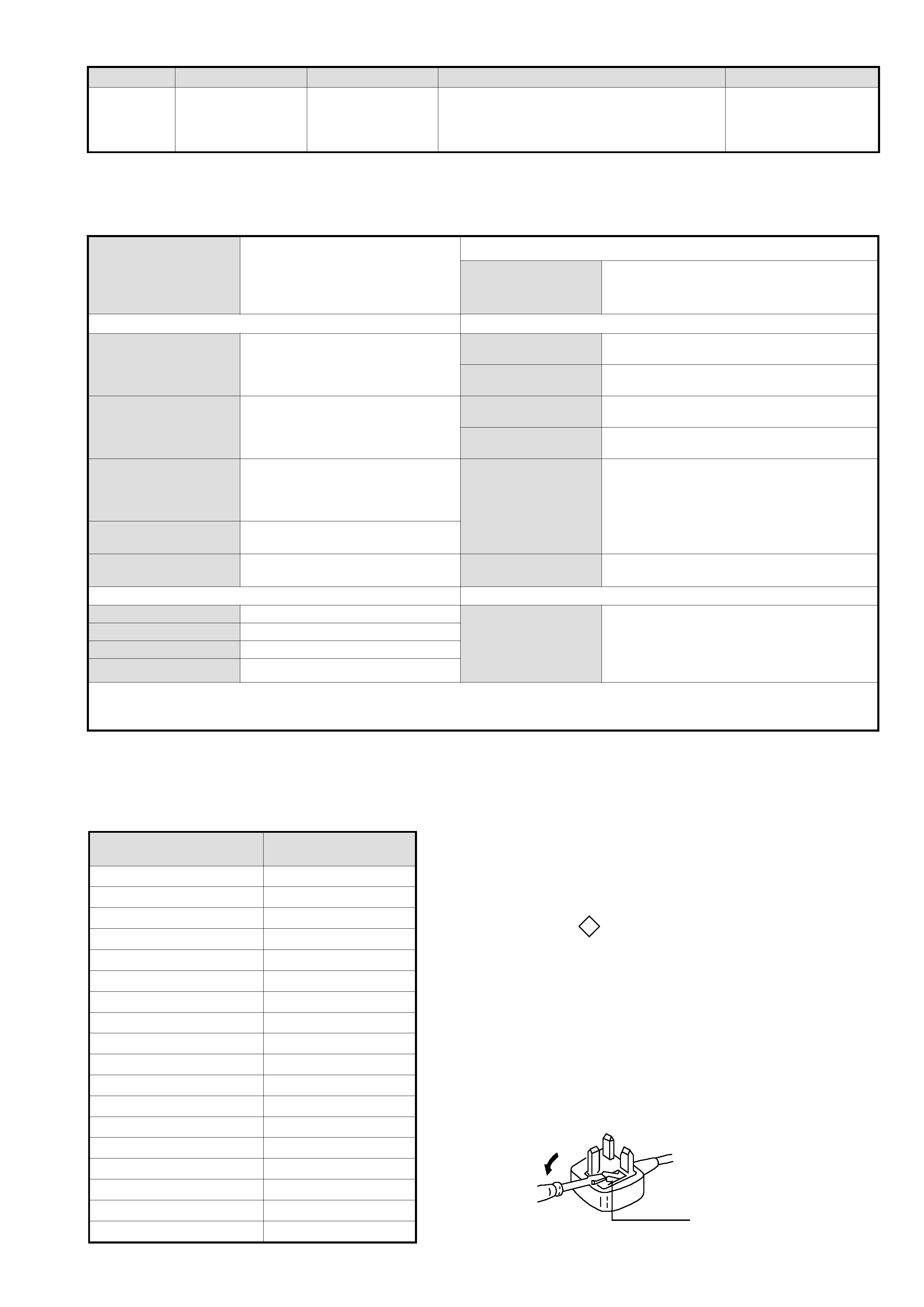
WARNING (UK Models only)
The flexible mains lead is supplied connected to a B.S. 1363 fused
plug having a fuse of 5 AMP rating. Should the fuse need to be
replaced, use a 5AMP FUSE approved by ASTA to BS 1362, ie one
that carries the ASA
T mark.
IF THE PLUG SUPPLIED WITH THIS APPLIANCE IS NOT SUIT-
ABLE FOR THE OUTLET SOCKETS IN YOUR HOME, IT SHOULD
BE CUT OFF AND AN APPROPRIATE PLUG FITTED. THE PLUG
SEVERED FROM THE MAINS LEAD MUST BE DESTROYED AS A
PLUG WITH BARED WIRES IS DANGEROUS IF ENGAGED IN A
LIVE SOCKET.
When an alternative type of plug is used, it should be fitted with a
5 AMP FUSE, otherwise the circuit should be protected by a 5AMP
FUSE at the distribution board.

- 5 -
Connected
Not Connected (open)
* at 20Hz - 20kHz
Pin No
1
2
4
Signal
Signal level
1
Audio output B
(right)
Standard level : 0.5V rms
Output impedence : Less than 1kohm*
2
Audio input B
(right)
Standard level : 0.5V rms
Output impedence : More than 10kohm*
3
Audio output A
(left)
Standard level : 0.5V rms
Output impedence : Less than 1kohm*
4
Ground (audio)
5
Ground (blue)
6
Audio input A
(left)
Standard level : 0.5V rms
Output impedence : More than 10kohm*
7
Blue input
0.7 +/- 3dB, 75 ohms positive
8
Function select
(AV control)
High state (9.5-12V) : Part mode
Low state (0-2V) : TV mode
Input impedence : More than 10K ohms
Input capacitance : Less than 2nF
9
Ground (green)
10
Open
11
Green
Green signal : 0.7 +/- 3dB, 75 ohms,
positive
12
Open
13
Ground (red)
14
Ground (blanking)
15
_
_
Red input
0.7 +/- 3dB, 75 ohms, positive
_
(S signal Chroma
input)
0.3 +/- 3dB, 75 ohms, positive
16
Blanking input
(Ys signal)
High state (1-3V) Low state (0-0.4V)
Input impedence : 75 ohms
17
Ground (video
output)
18
Ground (video
input)
19
Video output
1V +/- 3dB, 75ohms, positive sync 0.3V
(-3+10dB)
20
_
_
Video input
1V +/- 3dB, 75ohms, positive sync 0.3V
(-3+10dB)
_
Video input
Y (S signal)
1V +/- 3dB, 75ohms, positive sync 0.3V
(-3+10dB)
21
Common ground
(plug, shield)
21 pin connector
19
17
15
13
11
9
7
5
3
1
20
18
16
14
12
10
8
6
4
2
21
Rear Connection Panel
Front Connection Panel
n
o
i
t
a
r
u
g
i
f
n
o
c
n
i
p
t
e
k
c
o
s
o
e
d
i
V
S
n
i
P
o
N
l
a
n
g
i
S
l
e
v
e
L
l
a
n
g
i
S
1d
n
u
o
r
G-
2d
n
u
o
r
G-
3t
u
p
n
i
)
l
a
n
g
i
s
S
(
Y,
m
h
o
5
7
B
d
3
-
/
+
V
1
V
3
.
0
.
c
n
y
S
e
v
i
t
i
s
o
p
B
d
0
1
+
3
-
4t
u
p
n
i
)
l
a
n
g
i
s
S
(
CB
d
3
-
/
+
V
3
.
0
e
v
i
t
i
s
o
p
,
m
h
o
5
7
.
c
n
y
S
S-Video
socket
3