PIONEER ELECTRONIC CORPORATION
4-1, Meguro 1-Chome, Meguro-ku, Tokyo 153-8654, Japan
PIONEER ELECTRONICS SERVICE INC.
P.O.Box 1760, Long Beach, CA 90801-1760 U.S.A.
PIONEER ELECTRONIC [EUROPE] N.V.
Haven 1087 Keetberglaan 1, 9120 Melsele, Belgium
PIONEER ELECTRONICS ASIACENTRE PTE.LTD. 501 Orchard Road, #10-00, Wheelock Place, Singapore 238880
C PIONEER ELECTRONIC CORPORATION 1998
K-ZES. FEB. 1998 Printed in Japan
ORDER NO.
CRT2183
CD PLAYER
YPM-2136ZF
WL
Service
Manual
- See the separate manual CX-597(CRT1829) for the CD mechanism description, disassembly and circuit
description.
- The CD mechanism employed in this model is one of S7 series.
CONTENTS
1. SAFETY INFORMATION ............................................2
2. EXPLODED VIEWS AND PARTS LIST .......................4
3. SCHEMATIC DIAGRAM .............................................6
4. PCB CONNECTION DIAGRAM ................................16
5. ELECTRICAL PARTS LIST ........................................18
- CD Player Service Precautions
1. For pickup unit(CXX1232) handling, please refer
to"Disassembly"(CX-597 Service Manual CRT1829).
During replacement, handling precautions shall be
taken to prevent an electrostatic discharge(protection
by a short pin).
2. During disassembly, be sure to turn the power off
since an internal IC might be destroyed when a con-
nector is plugged or unplugged.
- This additional service manual is designed to be used together with Model YPM-1016ZF/UC Service
Manual CRT2111. Refer to it for finding parts numbers and adjustment, etc. which are not shown in
this manual.
2
YPM-2136ZF
1. SAFETY INFORMATION
This service manual is intended for qualified service technicians; it is not meant for the casual do-it-yourselfer.
Qualified technicians have the necessary test equipment and tools, and have been trained to properly and safely repair
complex products such as those covered by this manual.
Improperly performed repairs can adversely affect the safety and reliability of the product and may void the warranty.
If you are not qualified to perform the repair of this product properly and safely; you should not risk trying to do so
and refer the repair to a qualified service technician.
1. Safety Precautions for those who Service this Unit.
· When checking or adjusting the emitting power of the laser diode exercise caution in order to get safe, reliable
results.
Caution:
1. During repair or tests, minimum distance of 13cm from the focus lens must be kept.
2. During repair or tests, do not view laser beam for 10 seconds or longer.
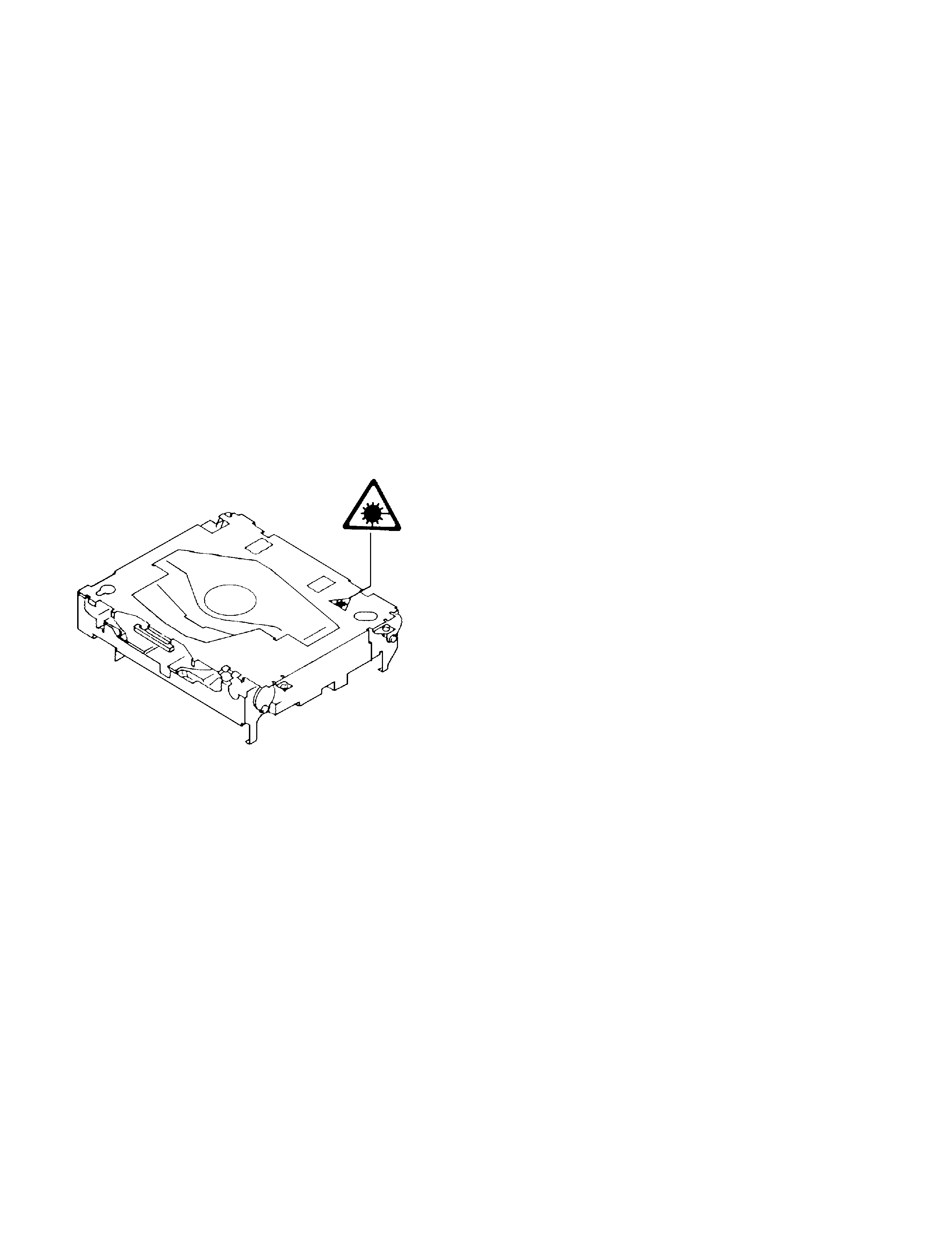
2. The triangular label is attached to the mechanism
unit frame.
4. Specifications of Laser Diode
Specifications of laser radiation fields to which human access is possible during service.
Wavelength
=
800 nanometers

3
YPM-2136ZF
4
YPM-2136ZF
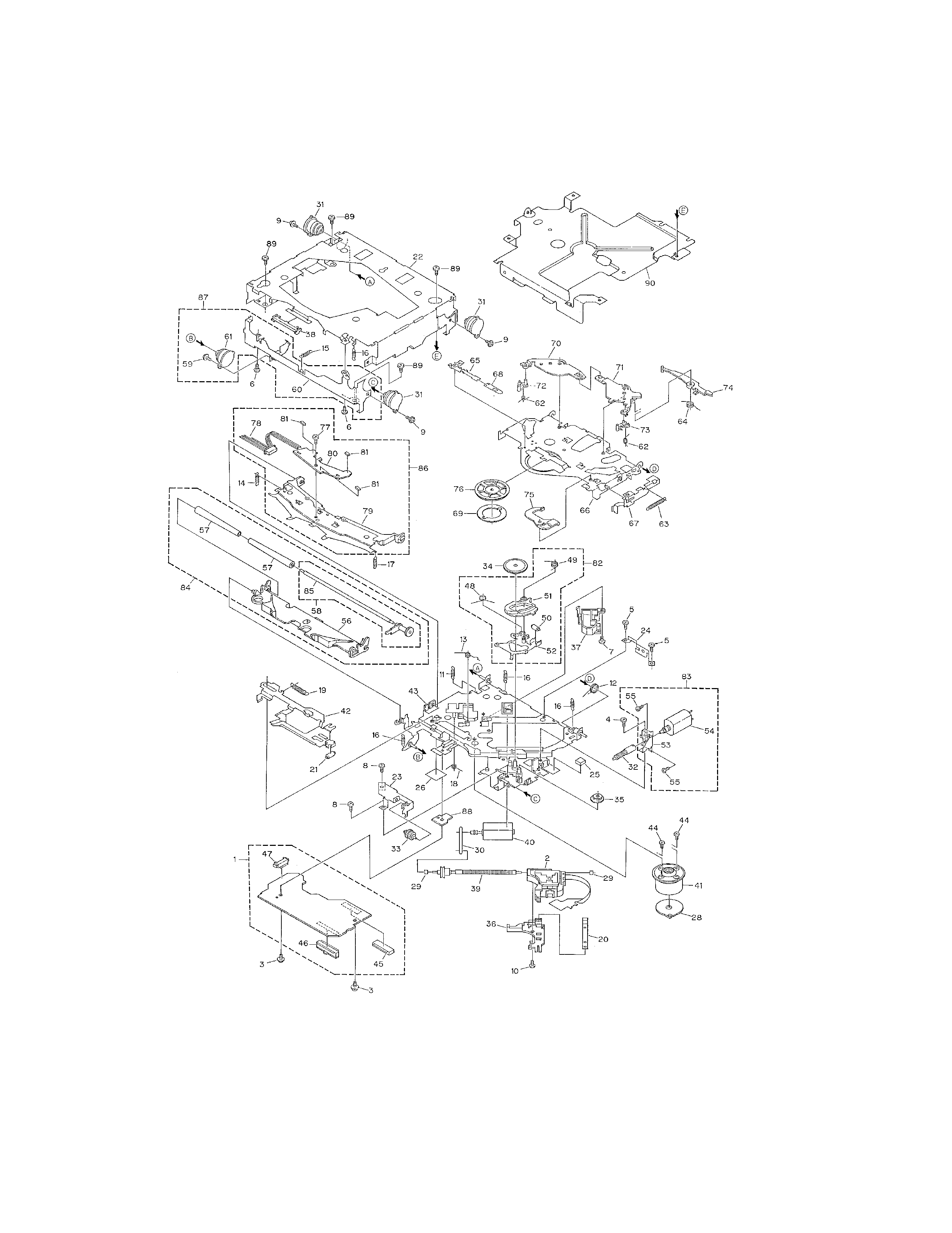
2. EXPLODED VIEWS AND PARTS LIST
2.1 CD MECHANISM MODULE
Fig. 1

5
YPM-2136ZF
1 Control Unit
CWX2158
2 Pickup Unit (Service)
CXX1232
3 Screw
IMS26P050FMC
4 Screw
BMZ20P025FMC
5 Screw
BMZ20P040FMC
6 Screw
BSZ20P040FMC
7 Screw (M2X3)
CBA1077
8 Screw (M2X2)
CBA1250
9 Screw (M2X5)
CBA1296
10 Screw (M2X3.85)
CBA1362
11 Spring
CBH1724
12 Spring
CBH1729
13 Spring
CBH1730
14 Spring
CBH1731
15 Spring
CBH1732
16 Spring
CBH1745
17 Spring
CBH1848
18 Spring
CBH1849
19 Spring
CBH1939
20 Spring
CBL1214
21 Roller
CLA2627
22 Frame
CNC6670
23 Bracket
CNC5871
*
24 Bracket
CNC6376
25 Cushion
CNM3917
26 Sheet
CNM4873
*
27 ·····
28 PCB
CNP4230
29 Bearing
CNR1415
30 Belt
CNT1071
31 Damper
CNV3974
32 Gear
CNV4128
33 Gear
CNV4129
34 Gear
CNV4857
35 Gear
CNV4131
36 Holder
CNV4663
37 Holder
CNV4664
38 Guide
CNV4484
39 Screw Unit
CXA8699
40 CRG Motor Unit (M2)
CXA8986
41 Motor Unit (M1)
CXB1562
42 Lever Unit
CXB1263
43 Chassis Unit
CXB1264
44 Screw
JGZ17P025FZK
45 Connector (CN101)
CKS1953
46 Connector (CN901)
CKS3422
47 Connector (CN801)
CKS2196
48 Spring
CBH1832
49 Spring
CBH1833
50 Roller
CLA2627
51 Arm
CNV4136
52 Arm Unit
CXA8565
53 Bracket
CNC6056
54 Load Motor Unit (M3)
CXB1631
55 Screw
JFZ20P025FMC
56 Arm
CNV4120
57 Roller
CNV4509
58 Gear Unit
CXA8701
59 Screw (M2X5)
CBA1296
60 Frame
CNC6844
61 Damper
CNV3974
62 Spring
CBH1736
63 Spring
CBH1863
64 Spring
CBH1945
65 Spring
CBL1269
66 Arm
CNC5799
67 Lever
CNC6054
68 Spacer
CNM3315
69 Sheet
CNM4849
70 Arm
CNV4122
71 Arm
CNV4123
72 Arm
CNV4124
73 Arm
CNV4125
74 Arm
CNV4138
75 Arm
CNV4139
76 Clamper
CNV4140
77 Screw (M2X2)
CBA1250
78 Connector
CDE4576
79 Arm
CNC5801
*
80 Gathering PCB
CNX2533
81 Photo-transistor (Q1,2,3) CPT-230S-X
82 Elbo Arm Assy
CXA8889
83 Load Motor Assy
CXB1632
84 LO Arm Assy
CXA8892
85 Shaft
CLA3133
86 Guide Arm Assy
CXA9416
87 F Frame Assy
CXB1068
88 Bracket
CNC6913
89 Screw
BSZ26P050FMC
90 Bracket
CNC7482
Mark No. Description
Part No.
Mark No. Description
Part No.
- CD MECHANISM MODULE SECTION PARTS LIST
NOTE:
- Parts marked by "*"are generally unavailable because they are not in our Master Spare Parts List.
- Screws adjacent to
mark on the product are used for disassembly.