ORDER NO.
PIONEER CORPORATION 4-1, Meguro 1-chome, Meguro-ku, Tokyo 153-8654, Japan
PIONEER ELECTRONICS SERVICE, INC. P.O. Box 1760, Long Beach, CA 90801-1760, U.S.A.
PIONEER EUROPE NV Haven 1087, Keetberglaan 1, 9120 Melsele, Belgium
PIONEER ELECTRONICS ASIACENTRE PTE. LTD. 253 Alexandra Road, #04-01, Singapore 159936
PIONEER CORPORATION 2001
c
Type
Model
Power Requirement
Region No.
Remarks
XV-HTD1
MYXJ
AC220-230V
2
NVXJ
AC230V
2
XV-HTD1
RRV2460
T ZZK MAY 2001 Printed in Japan
THIS MANUAL IS APPLICABLE TO THE FOLLOWING MODEL(S) AND TYPE(S).
DVD RECEIVER
1. SAFETY INFORMATION ....................................... 2
2. EXPLODED VIEWS AND PARTS LIST ................. 3
3. BLOCK DIAGRAM AND SCHEMATIC DIAGRAM ... 10
4. PCB CONNECTION DIAGRAM ........................... 46
5. PCB PARTS LIST ................................................ 66
6. ADJUSTMENT ..................................................... 73
7. GENERAL INFORMATION ................................ 74
7.1 DIAGNOSIS .................................................. 74
7.1.1 SELF-DIAGNOSTIC FUNCTION OF
PICKUP DEFECTIVE ........................... 74
7.1.2 TEST POINTS LOCATION ................... 75
CONTENTS
Component
System
Service Manual
Remarks
DVD SURROUND SYSTEM
DVD RECEIVER
XV-HTD1
RRV2460
This service manual
SPEAKER SYSTEM
S-HTD1
RRV2456
This product is component of system.
7.1.3 TEST MODE SCREEN DISPLAY ........ 76
7.1.4 POWER ON SEQUENCE .................... 78
7.1.5 TROUBLE SHOOTING ........................ 79
7.1.6 ERROR CODE ..................................... 80
7.1.7 DISASSEMBLY .................................... 84
7.1.8 TROUBLE SHOOTING FOR
MECHANISM SECTION ....................... 95
7.2 PARTS .......................................................... 98
7.2.1 IC .......................................................... 98
7.2.2 DISPLAY ............................................. 117
8. PANEL FACILITIES AND SPECIFICATIONS .. 118
2
XV-HTD1
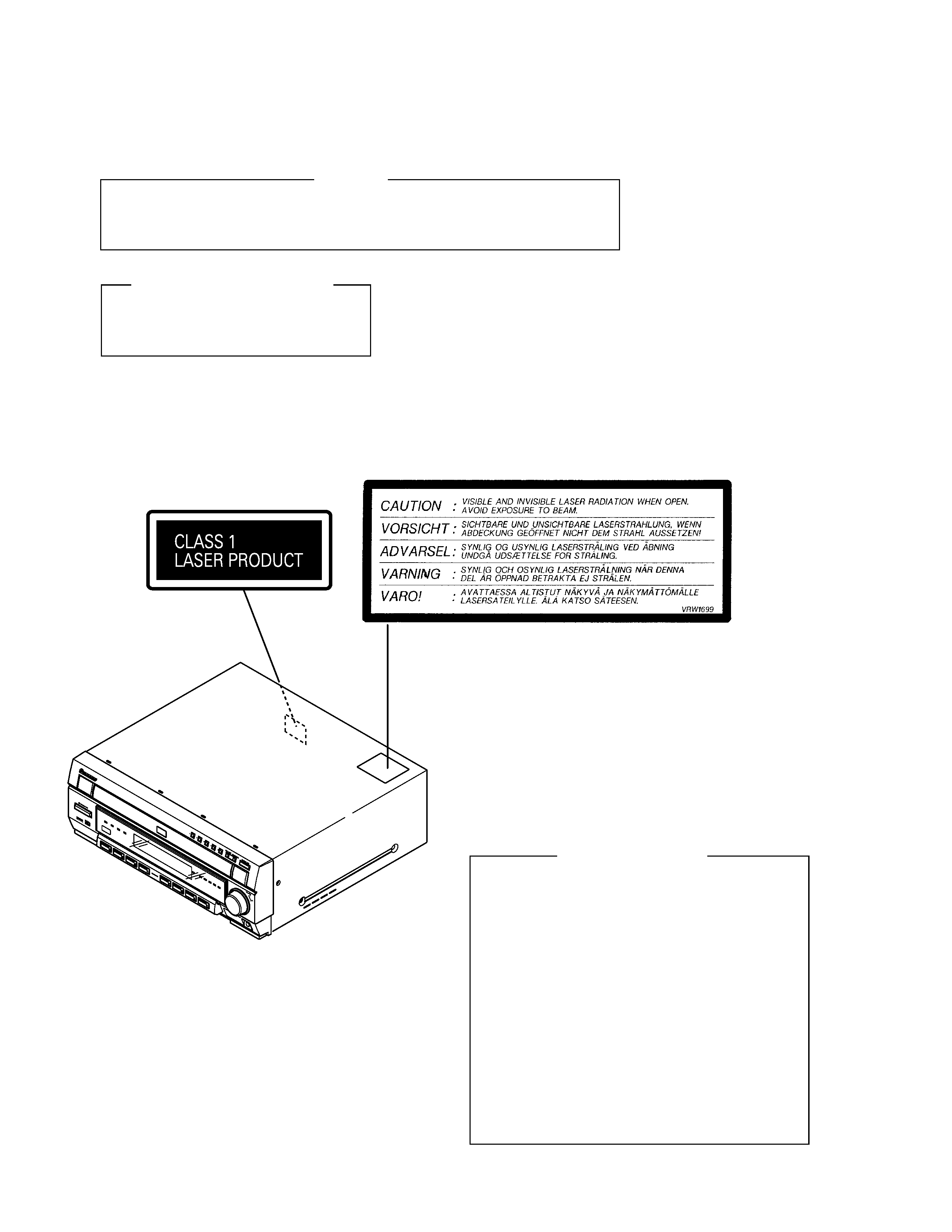
Printed on the Rear Panel
1. SAFETY INFORMATION
WARNING
THE AEL(ACCESSIBLE EMISSION LEVEL) OF THE LASER POWER OUTPUT IS LESS THAN CLASS 1
BUT THE LASER COMPONENT IS CAPABLE OF EMITTING RADIATION EXCEEDING THE LIMIT FOR
CLASS1.
A SPECIALLY INSTRUCTED PERSON SHOULD DO SERVICING OPERATION OF THE APPARATUS.
LASER DIODE CHARACTERISTICS
FOR DVD : MAXIMUM OUTPUT POWER : 5 mW
WAVELENGTH : 655 nm
FOR CD :
MAXIMUM OUTPUT POWER : 5mW
WAVELENGTH : 785 nm
Additional Laser Caution
1. Inside detection switch (S201 on the SMEB assy) and clamp-
status detection switch (S11 on the TRSB assy) are detected by
the microprocessor (IC11 in the DVDM assy).
· To permit the laser diode to oscillate, it is required to set the
inside detection switch for the inside position (S201 : ON) and to
set the loading-status detection switch for the clamp position (the
center terminal of S11 is shorted to +5V). The 655 nm laser diode
for DVD oscillation will continue if pin 19 of IC1 is shorted to +5V
(fault condition) in the DVDM assy.
The 785 nm laser diode for CD oscillates if pin 20 of IC1 is shorted
to +5V in the DVDM assy.
In the test mode
, the laser diode oscillates when microproces-
sor detects a PLAY signal, or when the PLAY key is pressed
(S5817 ON in the KEYB assy), with the above requirements sat-
isfied.
2. When the cover is open, close viewing through the objective lens
with the naked eye will cause exposure to the laser beam.
: See page 74.
LABEL CHECK
3
XV-HTD1
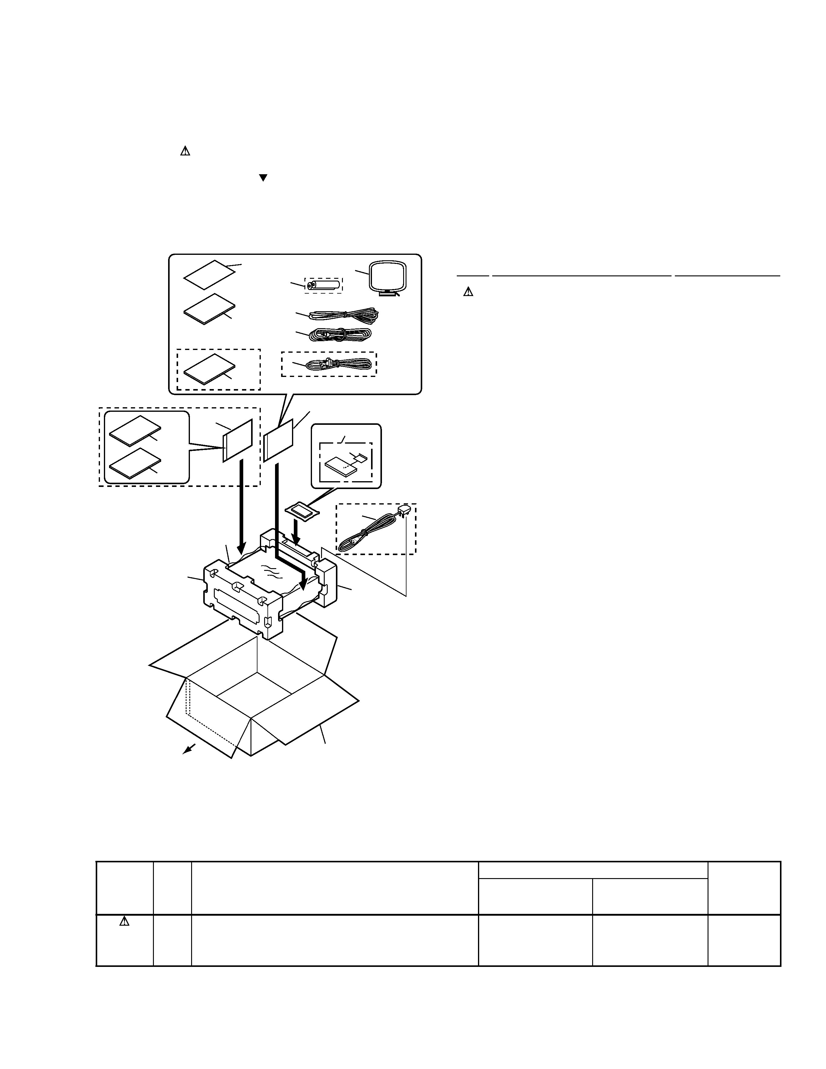
2.1 PACKING
(1) PACKING PARTS LIST
Mark No.
Description
Part No.
2. EXPLODED VIEWS AND PARTS LIST
NOTES:
· Parts marked by "NSP" are generally unavailable because they are not in our Master Spare Parts List.
· The mark found on some component parts indicates the importance of the safety factor of the part.
Therefore, when replacing, be sure to use parts of identical designation.
· Screws adjacent to mark on the product are used for disassembly.
1
Power Cord
See Contrast table (2)
2
FM Antenna
ADH7005
3
Video Cord (L = 1.5m)
VDE1053
4
Remote Control Unit
XXD3033
5
Battery Cover
XZN3117
NSP
6
Dry Cell Battery (R6P, AA)
VEM-013
7
Pad F
XHA3124
8
Pad R
XHA3125
9
Packing Case
XHD3193
10
Packing Sheet
AHG7010
11
Polyethylene Bag
Z21-038
NSP
12
Warranty Card
ARY7022
13
Operating Instructions (English) XRB3006
14
Operating Instructions
See Contrast table (2)
(French/German/Italian)
15
AM Loop Antenna
ATB7009
16
Operating Instructions
See Contrast table (2)
(Dutch/Swedish/Portuguese)
17
Operating Instructions
See Contrast table (2)
(Spanish)
FRONT
14
16
MYXJ Type
Only
17
MYXJ
Type
Only
NVXJ Type Only
MYXJ Type Only
1
12
5
13
4
6
11
11
15
3
2
1
8
9
7
10
(2) CONTRAST TABLE
XV-HTD1/MYXJ and NVXJ are constructed the same except for the following :
Part No.
Mark
No.
Symbol and Description
XV-HTD1
XV-HTD1
Remarks
/MYXJ
/NVXJ
1
Power Cord
ADG1154
ADG1156
14
Operating Instructions (French/German/Italian)
XRC3034
Not used
16
Operating Instructions (Dutch/Swedish/Portuguese)
XRC3035
Not used
17
Operating Instructions (Spanish)
XRC3036
Not used
4
XV-HTD1
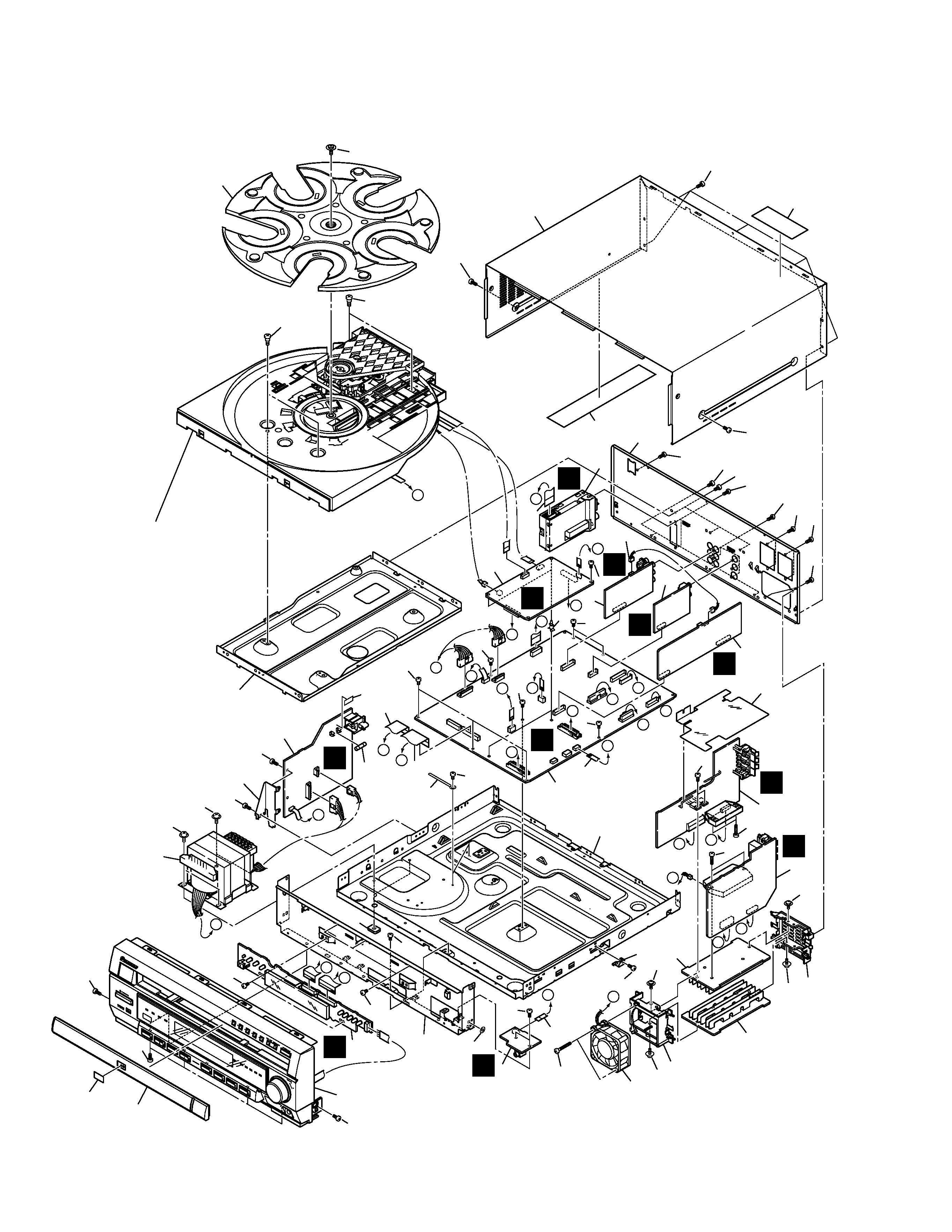
2.2 EXTERIOR
A
B
C
D
A
B
L
N
I
G
I
F
G
F
E
H
J
K
H
J
M
M
E
D
L
O
O
N
C
K
Refer to
"2.4 TABLE MECHANISM SECTION".
Refer to
"2.3 FRONT PANEL SECTION".
J
K
F
L
I
M
H
G
T
N
O
23
44
41
47
47
31
26
2
25
12
24
6
46
18
27
29
14
30
28
28
34
3
4
32
33
10
8
20
7
1
11
22
38
37
15
19
9
21
5
36
35
13
17
16
39
44
44
48
43
43
43
48
48
48
48
48
43
43
43
44
43
43
43
40
40
40
40
45
45
43
43
49
43
43
43
42
42
43
43
44
44
44
50

5
XV-HTD1
(1) EXTERIOR PARTS LIST
Mark No.
Description
Part No.
1
DVDM Assy
XWX3034
2
PRIMARY Assy
XWZ3433
3
FRONT AMP Assy
XWZ3439
4
REAR AMP Assy
XWZ3443
5
DISPLAY Assy
XWZ3446
6
MIC HP Assy
XWZ3451
7
INPUT Assy
XWZ3456
8
VIDEO Assy
XWZ3460
9
MAIN Assy
XWX3031
10
DSP Assy
XWX3040
11
TUNER MODULE
AXQ7229
12
T1 Power Transformer
XTS3052
13
FU1 Fuse (T3.15A)
REK1027
14
DC Fan Motor
AXM7014
15
13P F.F.C/60V
XDD3089
(MAIN CN5701 TUNER CN201)
16
19P F.F.C/60V
XDD3090
(MAIN CN5509 DISPLAY CN5801)
17
27P F.F.C/60V
XDD3091
(MAIN CN5511 DISPLAY CN5802)
18
5P F.F.C/60V
XDD3093
(MAIN CN5501 MIC HP CN5807)
19
7P F.F.C/60V
XDD3094
(MAIN CN8902 DVDM CN55)
20
Connector Assy 3P
XDE3041
(INPUT CN5207 DSP CN3703)
NSP
21
Chassis
XNA3008
22
Rear Panel
See Contrast table (2)
23
Bonnet Case
XZN3118
24
Front Frame
XNG3056
25
PCB Angle
XNG3057
26
Mecha Frame
XNG3059
Mark No.
Description
Part No.
27
DV Bracket
XNG3064
28
Heat Sink
XNH3021
NSP
29
Spacer
XEB3019
30
Fan Mold
AMR7321
31
Rotary Tray
VNK4923
32
Barrier H
XEC3016
NSP
33
PCB Support
XEC3020
34
Rear Mold
XMR3038
35
DVDV Badge
XAM3003
36
Tray Cap
XAN3032
37
Caution Label
VRW1699
NSP
38
Large Label
XAX3217
39
Cord Clamper
RNH-184
40
Screw
ABA1021
41
Screw
ABA7069
42
Screw
ASZ40P060FMC
43
Screw
BBZ30P060FMC
44
Screw
BBZ30P080FZK
45
Screw
BBZ30P160FMC
46
Screw
BPZ30P350FZK
47
Screw
PBA1106
48
Screw
VPZ30P080FZK
49
Washer
VEC1254
50
Fuse Card
AAX7493
(2) CONTRAST TABLE
XV-HTD1/MYXJ and NVXJ are constructed the same except for the following :
Part No.
Mark
No.
Symbol and Description
XV-HTD1
XV-HTD1
Remarks
/MYXJ
/NVXJ
22
Rear Panel
XNC3098
XNC3099