PIONEER CORPORATION 4-1, Meguro 1-chome, Meguro-ku, Tokyo 153-8654, Japan
PIONEER ELECTRONICS (USA) INC. P.O. Box 1760, Long Beach, CA 90801-1760, U.S.A.
PIONEER EUROPE NV Haven 1087, Keetberglaan 1, 9120 Melsele, Belgium
PIONEER ELECTRONICS ASIACENTRE PTE. LTD. 253 Alexandra Road, #04-01, Singapore 159936
PIONEER CORPORATION 2001
ORDER NO.
RRV2529
T ZZK AUG. 2001 Printed in Japan
Model No.
Order No.
Remarks
XV-HTD1/MYXJ
RRV2460
¶ This service manual should be used together with the following manual(s):
DVD RECEIVER
XV-HTD1
THIS MANUAL IS APPLICABLE TO THE FOLLOWING MODEL(S) AND TYPE(S).
Type
Model
Power Requirement
Region No.
Remarks
XV-HTD1
NKXJ
AC220V
3
Component
System
Service Manual
Remarks
DVD SURROUND SYSTEM
DVD RECEIVER
XV-HTD1
RRV2529 (RRV2460)
This service manual
SPEAKER SYSTEM
S-HTD1
RRV2456
This product is component of system.
CONTENTS
1. SAFETY INFORMATION ...................................... 2
2. CONTRAST OF MISCELLANEOUS PARTS ........ 3
3. SCHEMATIC DIAGRAM ....................................... 6
XV-HTD1
2
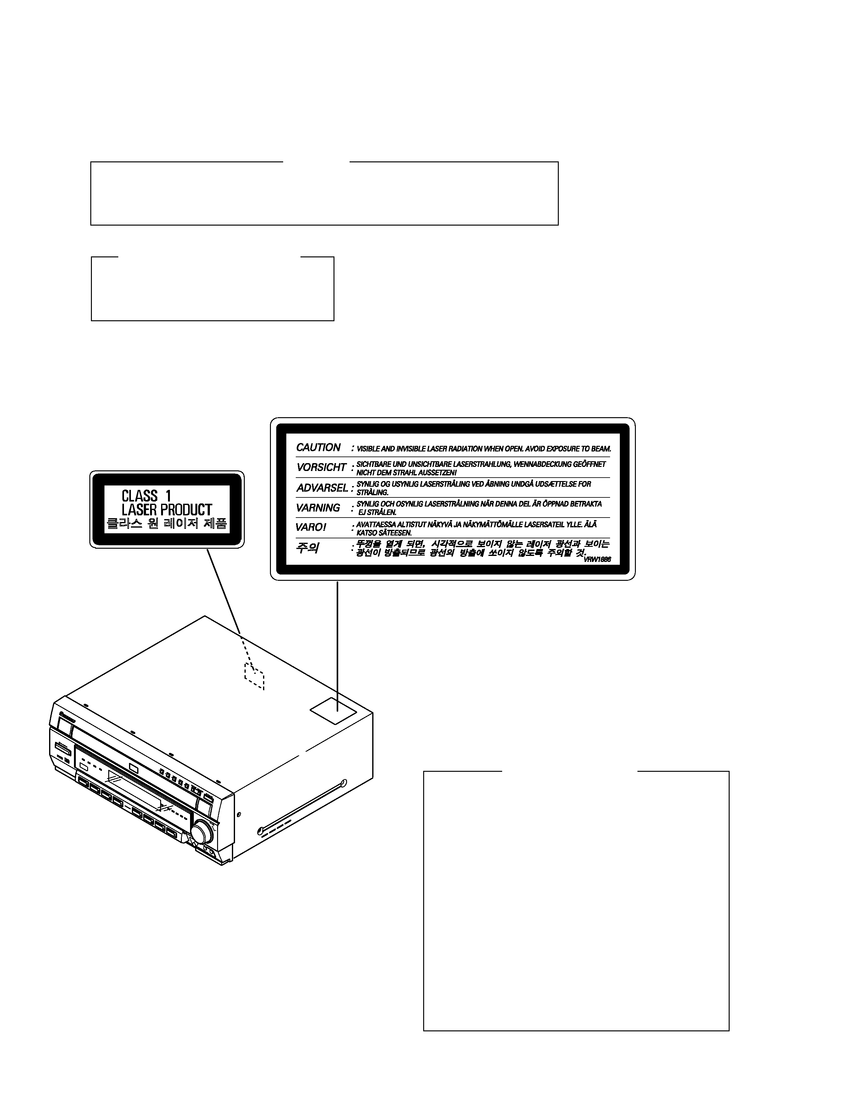
Printed on the Rear Panel
1. SAFETY INFORMATION
WARNING
THE AEL(ACCESSIBLE EMISSION LEVEL) OF THE LASER POWER OUTPUT IS LESS THAN CLASS 1
BUT THE LASER COMPONENT IS CAPABLE OF EMITTING RADIATION EXCEEDING THE LIMIT FOR
CLASS1.
A SPECIALLY INSTRUCTED PERSON SHOULD DO SERVICING OPERATION OF THE APPARATUS.
LASER DIODE CHARACTERISTICS
FOR DVD : MAXIMUM OUTPUT POWER : 5 mW
WAVELENGTH : 655 nm
FOR CD :
MAXIMUM OUTPUT POWER : 5mW
WAVELENGTH : 785 nm
Additional Laser Caution
1. Inside detection switch (S201 on the SMEB assy) and clamp-
status detection switch (S11 on the TRSB assy) are detected by
the microprocessor (IC11 in the DVDM assy).
· To permit the laser diode to oscillate, it is required to set the
inside detection switch for the inside position (S201 : ON) and to
set the loading-status detection switch for the clamp position (the
center terminal of S11 is shorted to +3.3V). The 655 nm laser
diode for DVD oscillation will continue if pin 19 of IC1 is shorted
to +5V (fault condition) in the DVDM assy.
The 785 nm laser diode for CD oscillates if pin 20 of IC1 is shorted
to +5V in the DVDM assy.
In the test mode
, the laser diode oscillates when microproces-
sor detects a PLAY signal, or when the PLAY key is pressed
(S5817 ON in the KEYB assy), with the above requirements sat-
isfied.
2. When the cover is open, close viewing through the objective lens
with the naked eye will cause exposure to the laser beam.
: Refer to page 74 on service manual RRV2460.
LABEL CHECK
XV-HTD1
3
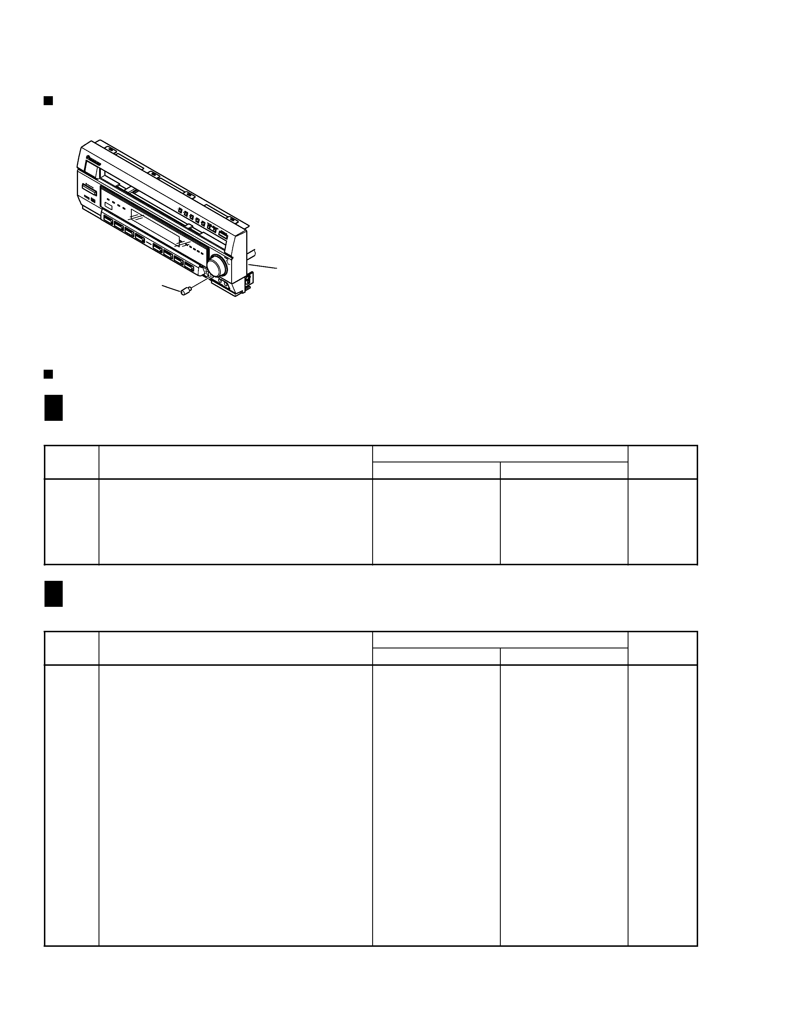
2. CONTRAST OF MISCELLANEOUS PARTS
CONTRAST TABLE
Part No.
Ref. No. Mark
Symbol and Description
XV-HTD1
XV-HTD1
Remarks
/MYXJ
/NKXJ
PCB ASSEMBLIES
NSP COMPLEX ASSY
XWM3188
XWM3192
P5- 2
PRIMARY ASSY
XWZ3433
XWZ3437
P5- 3
FRONT AMP ASSY
XWZ3439
XWZ3441
P5- 4
REAR AMP ASSY
XWZ3443
XWZ3445
P5- 6
MIC HP ASSY
XWZ3451
XWZ3452
NSP CONNECT ASSY
XWM3194
XWM3196
P5- 7
INPUT ASSY
XWZ3456
XWZ3458
P5- 9
MAIN ASSY
XWX3031
XWX3043
P5-10
DSP ASSY
XWX3040
XWX3041
PACKING SECTION
P3- 1
Power Cord
ADG1154
DDG1086
P3- 9
Packing Case
XHD3193
XHD3194
P3-12
NSP Warranty Card
ARY7022
Not used
P3-13
Operating Instructions (English)
XRB3006
Not used
P3-14
Operating Instructions (French/German/Italian)
XRC3034
Not used
P3-16
Operating Instructions (Dutch/Swedish/Portuguese)
XRC3035
Not used
P3-17
Operating Instructions (Spanish)
XRC3036
Not used
Operating Instructions (Korean)
Not used
XRC3039
Region Label (For Packing Case)
Not used
VRW1702
EXTERIOR SECTION
P5-18
5P F.F.C/60V
XDD3093
Not used
P5-18
8P F.F.C/60V
Not used
XDD3092
P5-22
Rear Panel
XNC3098
XNC3105
P5-37
Caution Label
VRW1699
VRW1886
Mic Knob
Not used
XAB3014
No. 1
FRONT PANEL SECTION
P6- 5
NSP Front Panel Assy
XXG3072
XXG3073
P6- 6
Front Cap
XAK3212
XAK3211
P6- 7
Display Panel
XAK3214
XAK3215
XV-HTD1/NKXJ and MYXJ are constructed the same except for the following :
Parts marked by "NSP" are generally unavailable because they are not in our Master Spare Parts List.
The
mark found on some component parts indicates the importance of the safety factor of the part.
Therefore, when replacing, be sure to use parts of identical designation.
Screws adjacent to
mark on product are used for disassembly.
Reference Nos. indicate the pages and Nos. in the service manual for the base model.
NOTES:
When ordering resistors, first convert resistance values into code form as shown in the following examples.
Ex.1 When there are 2 effective digits (any digit apart from 0), such as 560 ohm and 47k ohm (tolerance is shown by J=5%,
and K=10%).
Ex.2 When there are 3 effective digits (such as in high precision metal film resistors).
561
473
R50
1R0
5621
560
47k
0.5
1
RD1/4PU
J
RD1/4PU
J
RN2H
K
RS1P
K
56 x 101
47 x 103
R50
1R0
561
473
5.62k
RN1/4PC
F
562 x 101
5621
Notes : For PCB ASSEMBLIES, Refer to "CONTRAST OF PCB ASSEMBLIES" and "3. SCHEMATIC DIAGRAM".
The numbers in the remarks column correspond to the numbers on the " EXPLODED VIEWS ".
XV-HTD1
4
CONTRAST OF PCB ASSEMBLIES
EXPLODED VIEWS
INPUT ASSY
F
K
Mark
Symbol and Description
Part No.
Remarks
XWZ3456
XWZ3458
IC5353
Not used
BA4558F-HT
C5241, C5247
Not used
CEAT100M50
C5242, C5248
Not used
CCSRCH470J50
C5271, C5272
CCSRCH101J50
CCSRCH221J50
R5241R5248
Not used
RS1/16S332J
R9001, R9002
RS1/16S0R0J
Not used
XWZ3458 and XWZ3456 are constructed the same except for the following :
MIC HP ASSY
F
O
Mark
Symbol and Description
Part No.
Remarks
XWZ3451
XWZ3452
IC5802
Not used
BA4558F-HT
C5805
Not used
CKSRYB681K50
C5806
Not used
CEAL1R0M50
C5807, C5812, C5813
Not used
CEAL100M16
C5808, C5814
Not used
CCSRCH101J50
C5809
Not used
CKSRYB471K50
C5810
Not used
CKSRYB104K25
C5811
Not used
CKSRYB473K25
R5814
Not used
RS1/16S101J
R5866
Not used
RS1/16S222J
R5867, R5872, R5874
Not used
RS1/16S104J
R5868, R5885
Not used
RS1/16S223J
R5869
Not used
RS1/16S224J
R5870
Not used
RS1/16S681J
R5871
Not used
RS1/16S102J
R5873
Not used
RS1/16S0R0J
VR5801
Not used
XCS3005
CN5807
5P FFC CONNECTOR
52044-0545
Not used
CN5807
8P FFC CONNECTOR
Not used
52044-0845
JA5801
MINI JACK
Not used
XKN3008
XWZ3452 and XWZ3451 are constructed the same except for the following :
Front Panel
1
XV-HTD1
5
FRONT AMP ASSY
F
G
Mark
Symbol and Description
Part No.
Remarks
XWZ3439
XWZ3441
C3773
Not used
CEAT101M35
XWZ3441 and XWZ3439 are constructed the same except for the following :
MAIN ASSY
F
I
Mark
Symbol and Description
Part No.
Remarks
XWX3031
XWX3043
IC3002, IC3181
Not used
BA4558F-HT
IC3151, IC3152, IC3161, IC3171
NJM4558MD
BA4558F-HT
IC5701
BU1923F
Not used
C3011, C3014
Not used
CEAT100M50
C3185
Not used
CEJQ100M35
C3186, C3187
Not used
CKSRYB473K25
C3913, C3914
CKSRYB103K50
CKSRYB102K50
C5701
CKSRYB271K50
Not used
C5702
CEAT100M50
Not used
C5704
CKSRYB103K50
Not used
C5705, C5706
CCSRCH270J50
Not used
C5707
CKSRYB561K50
Not used
C5708
CKSRYB104K25
Not used
C5830
Not used
CEAT101M10
C5831
Not used
CEAT101M25
R3181
Not used
RD1/4PU332J
R3182
Not used
RS1/16S332J
R3183, R3184, R3254, R3258, R3263, R3264, R5703
Not used
RS1/16S103J
R3186, R5705
RS1/16S0R0J
Not used
R3189, R3190
Not used
RS1/16S682J
R3255, R3257, R3259, R3261, R5702
Not used
RS1/16S473J
R3256, R3260
Not used
RS1/16S182J
R5558
RS1/16S153J
RS1/16S123J
R5559
RS1/16S562J
RS1/16S153J
R5701
RD1/4PU101J
Not used
R5830
Not used
RS1/16S224J
R5831
Not used
RS1/16S101J
CN5501
5P FFC CONNECTOR
52045-0545
Not used
CN5502
8P FFC CONNECTOR
Not used
52045-0845
KN5701
EARTH METAL FITTING
VNF1084
Not used
X5701
CRYSTAL RESONATOR (4.332MHz)
ASS7004
Not used
XWX3043 and XWX3031 are constructed the same except for the following :
Although XWX3041 and XWX3040 are different in part number, they consist of the same components.
DSP ASSY
F
M
PRIMARY ASSY
F
T
REAR AMP ASSY
F
H
Although XWZ3445 and XWZ3443 are different in part number, they consist of the same components.
Although XWZ3437 and XWZ3433 are different in part number, they consist of the same components.