ORDER NO.
PIONEER CORPORATION 4-1, Meguro 1-chome, Meguro-ku, Tokyo 153-8654, Japan
PIONEER ELECTRONICS (USA) INC. P.O. Box 1760, Long Beach, CA 90801-1760, U.S.A.
PIONEER EUROPE NV Haven 1087, Keetberglaan 1, 9120 Melsele, Belgium
PIONEER ELECTRONICS ASIACENTRE PTE. LTD. 253 Alexandra Road, #04-01, Singapore 159936
PIONEER CORPORATION 2004
DV IN/OUT
OPEN/CLOSE HDD/DVD
STOP REC
REC
STANDBY/ON
PULL OPEN
VOLUME
PLA
Y
STOP
0
XV-DVR9H
RRV3019
DVD-RW/HDD TUNER
XV-DVR9H
THIS MANUAL IS APPLICABLE TO THE FOLLOWING MODEL(S) AND TYPE(S).
Model
Type
Power Requirement
Regional restriction
codes (Region No.)
Remarks
XV-DVR9H
WYXJ
AC220-240V
2
XV-DVR9H
WVXJ
AC220-240V
2
÷ When servicing this model, some service procedures may reset the settings that customer set (*) to
the factory default settings. Make sure to explain this to the customer.
(*) : Initial Setup (Clock Setting, Tuner settings, Video In / Out settings, Audio In settings,
Audio Out settings, Language settings, Recording settings, Playback settings)
Refer to the chapter 15 of the Operating Instructions for more details.
An HDD (Hard Disc Drive) is mounted in this product.
The HDD is a precision instrument very vulnerable to shock and electrostatic charges. Please read
"7.4 Cautions on Handling the HDD" in this manual and exercise sufficient caution when handling the
HDD itself, as well as the product with the HDD built in.
When an HDD becomes defective and inoperable, restoration of the user's data recorded on the HDD,
or copying of the user's recorded data to other media (such as a new HDD) is totally impossible.
Before servicing, OBTAIN THE USER'S PRIOR CONSENT to that effect.
The user must be made aware that all recorded data are deleted if the HDD is intialized.
For details, refer to "Important Check Points for Good Servicing".
T-ZZK OCT. 2004 printed in Japan
XV-DVR9H
2
12
34
12
3
4
C
D
F
A
B
E
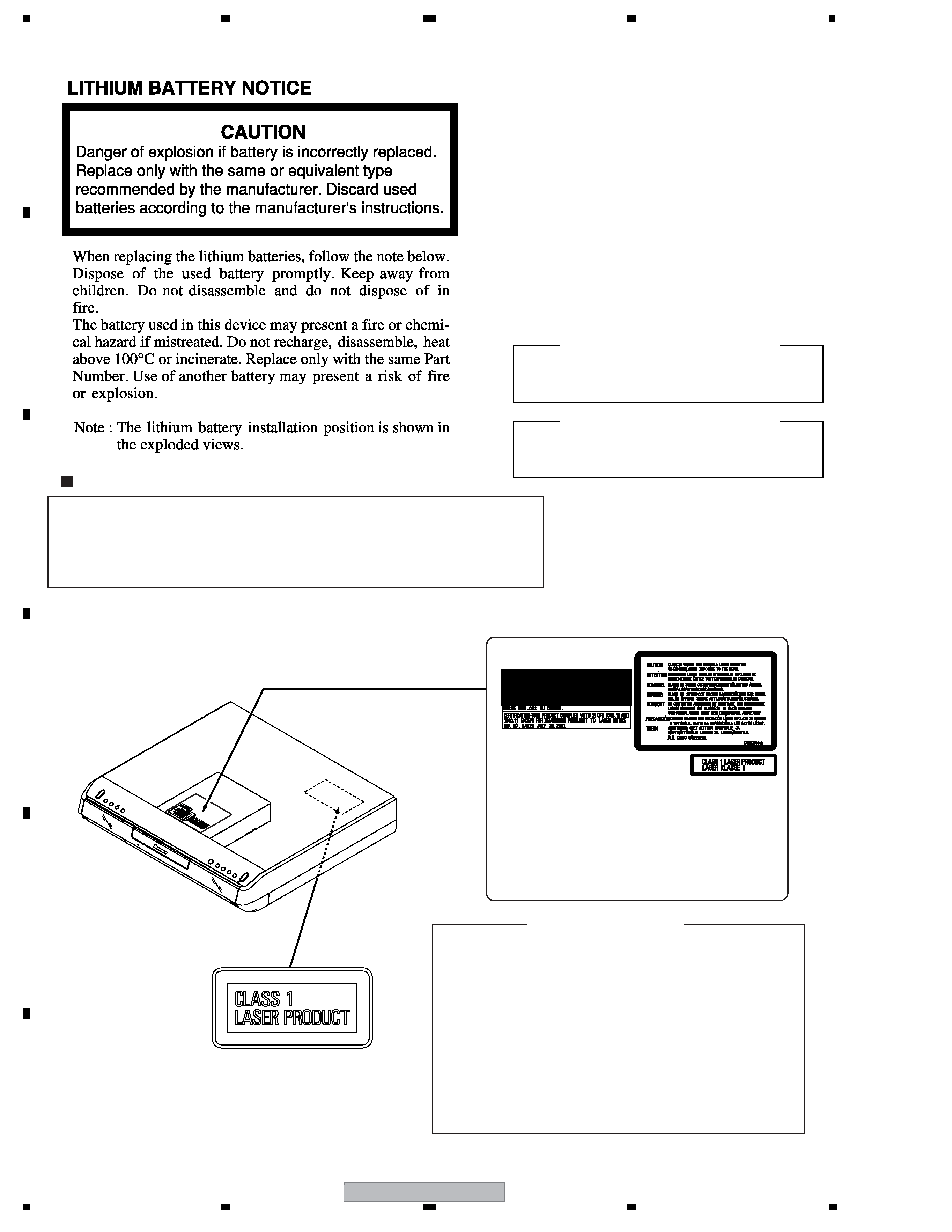
SAFETY INFORMATION
LABEL CHECK
CLAMP signals for detecting the loading state are detected
by the drive CPUs, and the design prevents laser diode
oscillation when the CLAMP signal turns OFF.
In normal operation, if no disc is clamped, the laser diode
oscillation is disabled.
However, the interlock does not always operate in the test
mode.
2. When the cover is opened, close viewing of the objective
lens with the naked eye will cause exposure to a Class 3A
laser beam.
Additional Laser Caution
1. The ON/OFF(ON:low level,OFF:high level) status of the
LASER DIODE CHARACTERISTICS
MAXIMUM OUTPUT POWER : 70 mW
PULSE WIDTH : 100ns DUTY : 50% 140mW
WAVELENGTH : 654 - 662 nm
LASER DIODE CHARACTERISTICS
MAXIMUM OUTPUT POWER : 100 mW
PULSE WIDTH : 100ns DUTY : 50% 240mW
WAVELENGTH : 780 - 787 nm
WARNING !
The AEL (accessible emission level) of the laser power output is less than CLASS 1
but the laser component is capable of emitting radiation exceeding the limit for
CLASS 1.
A specially instructed person should do servicing operation of the apparatus.
(Printed on License Label)
DRW2194
XV-DVR9H
3
56
78
56
7
8
C
D
F
A
B
E
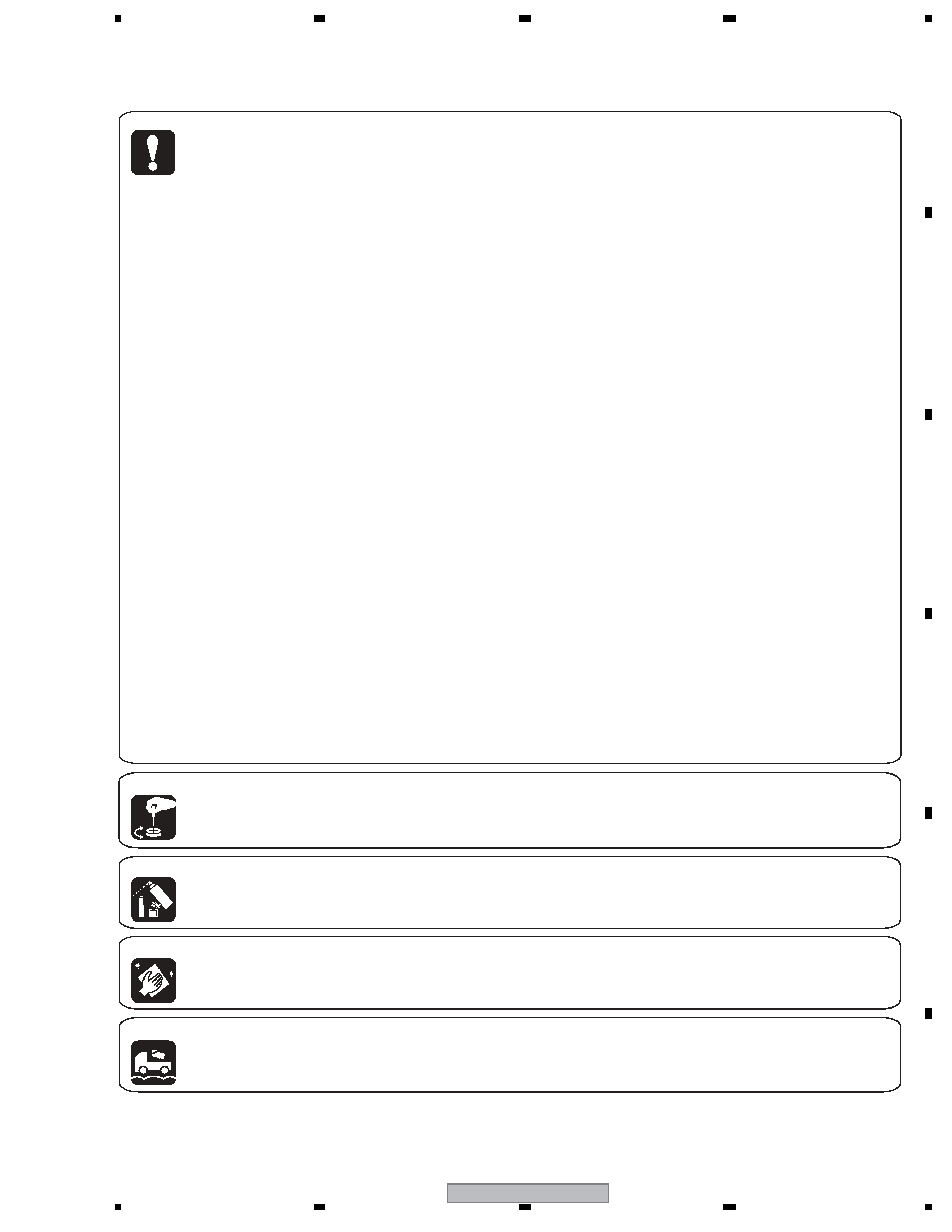
[Important Check Points for Good Servicing]
In this manual, procedures that must be performed during repairs are marked with the below symbol.
Please be sure to confirm and follow these procedures.
1. Product safety
Please conform to product regulations (such as safety and radiation regulations), and maintain a safe servicing environment by
following the safety instructions described in this manual.
1 Use specified parts for repair.
Use genuine parts. Be sure to use important parts for safety.
2 Do not perform modifications without proper instructions.
Please follow the specified safety methods when modification(addition/change of parts) is required due to interferences such as
radio/TV interference and foreign noise.
3 Make sure the soldering of repaired locations is properly performed.
When you solder while repairing, please be sure that there are no cold solder and other debris.
Soldering should be finished with the proper quantity. (Refer to the example)
4 Make sure the screws are tightly fastened.
Please be sure that all screws are fastened, and that there are no loose screws.
5 Make sure each connectors are correctly inserted.
Please be sure that all connectors are inserted, and that there are no imperfect insertion.
6 Make sure the wiring cables are set to their original state.
Please replace the wiring and cables to the original state after repairs.
In addition, be sure that there are no pinched wires, etc.
7 Make sure screws and soldering scraps do not remain inside the product.
Please check that neither solder debris nor screws remain inside the product.
8 There should be no semi-broken wires, scratches, melting, etc. on the coating of the power cord.
Damaged power cords may lead to fire accidents, so please be sure that there are no damages.
If you find a damaged power cord, please exchange it with a suitable one.
9 There should be no spark traces or similar marks on the power plug.
When spark traces or similar marks are found on the power supply plug, please check the connection and advise on secure
connections and suitable usage. Please exchange the power cord if necessary.
0 Safe environment should be secured during servicing.
When you perform repairs, please pay attention to static electricity, furniture, household articles, etc. in order to prevent injuries.
Please pay attention to your surroundings and repair safely.
2. Adjustments
To keep the original performance of the products, optimum adjustments and confirmation of characteristics within specification.
Adjustments should be performed in accordance with the procedures/instructions described in this manual.
4. Cleaning
For parts that require cleaning, such as optical pickups, tape deck heads, lenses and mirrors used in projection monitors, proper
cleaning should be performed to restore their performances.
3. Lubricants, Glues, and Replacement parts
Use grease and adhesives that are equal to the specified substance.
Make sure the proper amount is applied.
5. Shipping mode and Shipping screws
To protect products from damages or failures during transit, the shipping mode should be set or the shipping screws should be
installed before shipment. Please be sure to follow this method especially if it is specified in this manual.

XV-DVR9H
4
12
34
12
3
4
C
D
F
A
B
E
CONTENTS
SAFETY INFORMATION ..................................................................................................................................... 2
1. SPECIFICATIONS ............................................................................................................................................ 5
2. EXPLODED VIEWS AND PARTS LIST ............................................................................................................ 8
2.1 PACKING ................................................................................................................................................... 8
2.2 EXTERIOR SECTION.............................................................................................................................. 10
2.3 CHASSIS SECTION ................................................................................................................................ 12
2.4 FRONT PANEL SECTION ....................................................................................................................... 14
3. BLOCK DIAGRAM AND SCHEMATIC DIAGRAM ..........................................................................................16
3.1 BLOCK DIAGRAM ................................................................................................................................... 16
3.1.1 OVERALL BLOCK DIAGRAM ........................................................................................................... 16
3.1.2 MAIN ASSY BLOCK DIAGRAM ........................................................................................................ 20
3.1.3 POWER SUPPLY BLOCK DIAGRAM................................................................................................22
3.2 OVERALL WIRING CONNECTION DIAGRAM........................................................................................ 24
3.3 TV MODULE ASSY.................................................................................................................................. 26
3.4 TV CONNECT ASSY ............................................................................................................................... 28
3.5 JACK ASSY (1/2) ..................................................................................................................................... 30
3.6 JACK ASSY (2/2) ..................................................................................................................................... 32
3.7 MAIN ASSY (1/5) ..................................................................................................................................... 34
3.8 MAIN ASSY (2/5) ..................................................................................................................................... 36
3.9 MAIN ASSY (3/5) ..................................................................................................................................... 38
3.10 MAIN (4/5), ATWB and ATHB ASSYS.................................................................................................... 40
3.11 MAIN ASSY (5/5) ................................................................................................................................... 42
3.12 CONTROL ASSY (1/4)........................................................................................................................... 44
3.13 CONTROL ASSY (2/4)........................................................................................................................... 46
3.14 CONTROL ASSY (3/4)........................................................................................................................... 48
3.15 CONTROL ASSY (4/4)........................................................................................................................... 50
3.16 DSP ASSY (1/2)..................................................................................................................................... 52
3.17 DSP ASSY (2/2)..................................................................................................................................... 54
3.18 REG, DISPLAY, LED, TRADE, F. JACK, IR, KEY L and KEY R ASSYS ................................................ 56
3.19 POWER SUPPLY UNIT.......................................................................................................................... 58
3.20 WAVEFORMS ........................................................................................................................................ 60
4. PCB CONNECTION DIAGRAM ..................................................................................................................... 63
4.1 TV MODULE ASSY.................................................................................................................................. 64
4.2 TV CONNECT ASSY ............................................................................................................................... 65
4.3 JACK and TRADE ASSYS ....................................................................................................................... 66
4.4 MAIN ASSY ............................................................................................................................................. 70
4.5 CONTROL ASSY ..................................................................................................................................... 74
4.6 DSP ASSY ............................................................................................................................................... 78
4.7 REG ASSY............................................................................................................................................... 80
4.8 DISPLAY and LED ASSYS ...................................................................................................................... 81
4.9 FRONT JACK ASSY ................................................................................................................................ 82
4.10 IR, KEY L and KEY R ASSYS ............................................................................................................... 83
4.11 ATWB and ATHB ASSYS ....................................................................................................................... 84
5. PCB PARTS LIST ........................................................................................................................................... 85
6. ADJUSTMENT ............................................................................................................................................... 92
6.1 TV MODULE ADJUSTMENT ................................................................................................................... 92
6.2 MAIN ASSY ADJUSTMENT .................................................................................................................... 93
7. GENERAL INFORMATION ............................................................................................................................. 94
7.1 DIAGNOSIS ............................................................................................................................................. 94
7.1.1 CPRM ID NUMBER AND DATA SETTING ........................................................................................ 95
7.1.2 MODEL SETTING ............................................................................................................................. 99
7.1.3 DOWNLOAD METHOD ................................................................................................................... 100
7.1.4 SERVICE MODE ............................................................................................................................. 102
7.1.5 ERROR RATE MEASUREMENT..................................................................................................... 117
7.1.6 SERVICE SPECIFICATIONS OF THE PT MICROCOMPUTER (PDC117A-K) .............................. 119
7.1.7 SPECIFICATIONS OF THE DSP DISPLAY ..................................................................................... 120
7.1.8 VIDEO ADJUSTMENT FOR SPECIFIC AREA ............................................................................... 123
7.1.9 AGING MODE ................................................................................................................................. 127
7.1.10 SETUP SEQUENCE...................................................................................................................... 129
7.1.11 DSP TROUBLE SHOOTING ......................................................................................................... 130
7.1.12 DISASSEMBLY.............................................................................................................................. 134
7.2 PARTS.................................................................................................................................................... 141
7.2.1 IC ..................................................................................................................................................... 141
7.3 DIAGNOSIS METHOD OF THE HDD.................................................................................................... 175
7.4 CAUTIONS ON HANDLING THE HDD .................................................................................................. 181
7.5 DISC/CONTENT FORMAT .................................................................................................................... 183
7.6 CLEANING............................................................................................................................................. 184
8. PANEL FACILITIES ...................................................................................................................................... 185
XV-DVR9H
5
56
78
56
7
8
C
D
F
A
B
E
1. SPECIFICATIONS
General
System . . . . . . . . . . . . . . . . HDD, DVD-Video, DVD-R/RW,
Video-CD, Super VCD, CD,
CD-R/RW (WMA, MP3, JPEG, CD-DA)
Power requirements . . . . . . . . . . . . . . 220-240 V, 50/60 Hz
Power consumption
XV-DVR9H . . . . . . . . . . . . . . . . . . . . . . . . . . . . . . . . 81 W
S-DVR9SW . . . . . . . . . . . . . . . . . . . . . . . . . . . . . . . 151 W
Power consumption in standby
XV-DVR9H . . . . . . . . . . . . . . . . . 0.80 W (front display off)
S-DVR9SW . . . . . . . . . . . . . . . . . . . . . . . . . . . . . . . . . 0 W
Dimensions . . . . . . . . . . . 420 (W) x 77.5 (H) x 398 (D) mm
Weight . . . . . . . . . . . . . . . . . . . . . . . . . . . . . . . . . . . . 5.6 kg
Operating temperature . . . . . . . . . . . . . . . . . +5ºC to +35ºC
Operating humidity . . . . . . . . . . . . . . . . . . . . . . . 5% to 85%
(no condensation)
TV system . . . . . . . . . . . . . . . . . . . . . . . . . . . . PAL/SECAM/
NTSC (external input only)
Recording
Recording format . . . . . . . . . . . . . . . DVD Video Recording
DVD-VIDEO
Recordable discs
DVD-RW (DVD Re-recordable disc)
DVD-R (DVD Recordable disc)
Video recording format
Sampling frequency . . . . . . . . . . . . . . . . . . . . . . . . 13.5MHz
Compression format . . . . . . . . . . . . . . . . . . . . . . . . . MPEG
Audio recording format
Sampling frequency . . . . . . . . . . . . . . . . . . . . . . . . . . 48kHz
Compression format . . . . . . . . .Dolby Digital or Linear PCM
(uncompressed)
Recording time
HDD
Fine (FINE) . . . . . . . . . . . . . . . . . . . . . . . . Approx. 17 hours
Standard Play (SP) . . . . . . . . . . . . . . . . . . Approx. 34 hours
Long Play (LP) . . . . . . . . . . . . . . . . . . . . . Approx. 68 hours
Extended Play (EP) . . . . . . . . . . . . . . . . Approx. 102 hours
Manual Mode (MN) . . . . . . . . . . . . .
Approx. 17-102 hours
DVD-R/DVD-RW
Fine (FINE) . . . . . . . . . . . . . . . . . . . . . . . . . . Approx. 1 hour
Standard Play (SP) . . . . . . . . . . . . . . . . . . . Approx. 2 hours
Long Play (LP) . . . . . . . . . . . . . . . . . . . . . . Approx. 4 hours
Extended Play (EP) . . . . . . . . . . . . . . . . . . Approx. 6 hours
Manual Mode (MN) . . . . . . . . . . . . . . . .
Approx. 1-6 hours
Amplifier section
Continuous Power Output (RMS):
Front, Center, Surround . . . . . . . . . . . . . 100 W per channel
(1 kHz, 10 % T.H.D., 6
)
Subwoofer . . . . . . . . . . . 100 W (100 Hz, 10 % T.H.D., 6
)
FM tuner section
Frequency range . . . . . . . . . . . . . . . . . . . . 87.5 to 108 MHz
Antenna . . . . . . . . . . . . . . . . . . . . . . . . . . 75
, unbalanced
AM tuner section
Frequency range . . . . . . . . . . . . . . . . 531 kHz to 1,602 kHz
Antenna . . . . . . . . . . . . . . . . . . . . . . . . . . . . . Loop antenna
Timer
Programs . . . . . . . . . . . . . . . . . . . . . . 1 month/32 programs
Clock . . . . . . . . . . . . . . Quartz lock (24-hour digital display)
Power off memory . . . . Approx. 5 years (after manufacture)
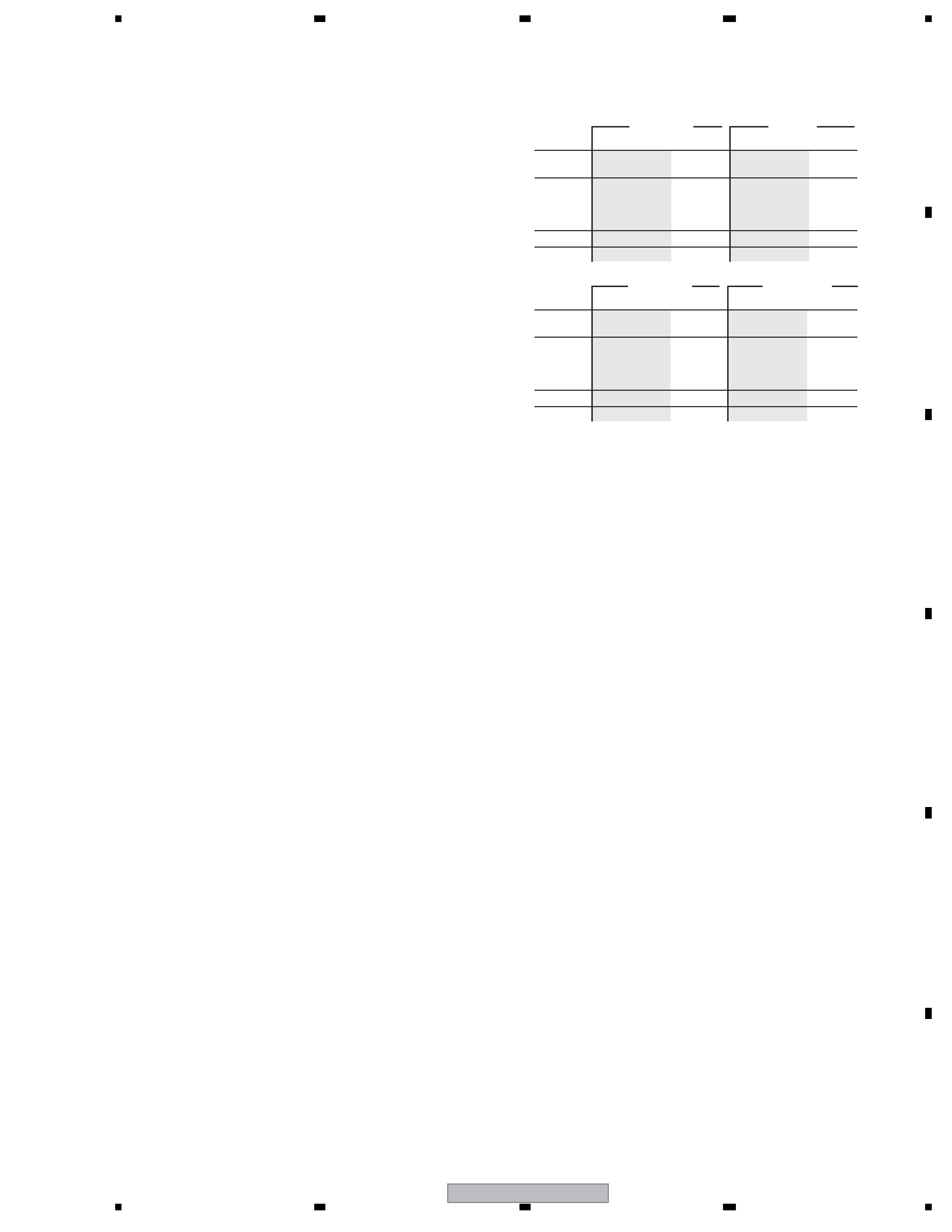
TV tuner section
Receivable channels
VHF (low)
VHF (high)
Hyper
UHF
VHF (low)
VHF (high)
Hyper
UHF
STEREO
B/G - A2
I - NICAM
L - NICAM
B/G - NICAM
D/K - NICAM
Channel
E2 - E4
X - Z
E5 - E12
S1 - S20
M1 - M10
U1 - U10
S21 - S41
E21 - E69
Frequency
47 - 89 MHz
104 - 300 MHz
302 - 470 MHz
470 - 862 MHz
Channel
A - C
X - Z
D - J
11, 13
S1 - S20
S21 - S41
E21 - E69
Frequency
44 - 89 MHz
104 - 300 MHz
302 - 470 MHz
470 - 862 MHz
PAL B/G
PAL I
Channel
2 - 4
5 - 10
B - Q
S21 - S41
21 - 69
Frequency
49 - 65 MHz
104 - 300 MHz
300 - 470 MHz
470 - 862 MHz
Channel
R1 - R5
R6 - R12
S1 - S20
S21 - S41
E21 - E69
Frequency
49 - 94 MHz
104 - 300 MHz
302 - 470 MHz
470 - 862 MHz
SECAM L
SECAM D/K