Setting Up the System
Installation de l'appareil
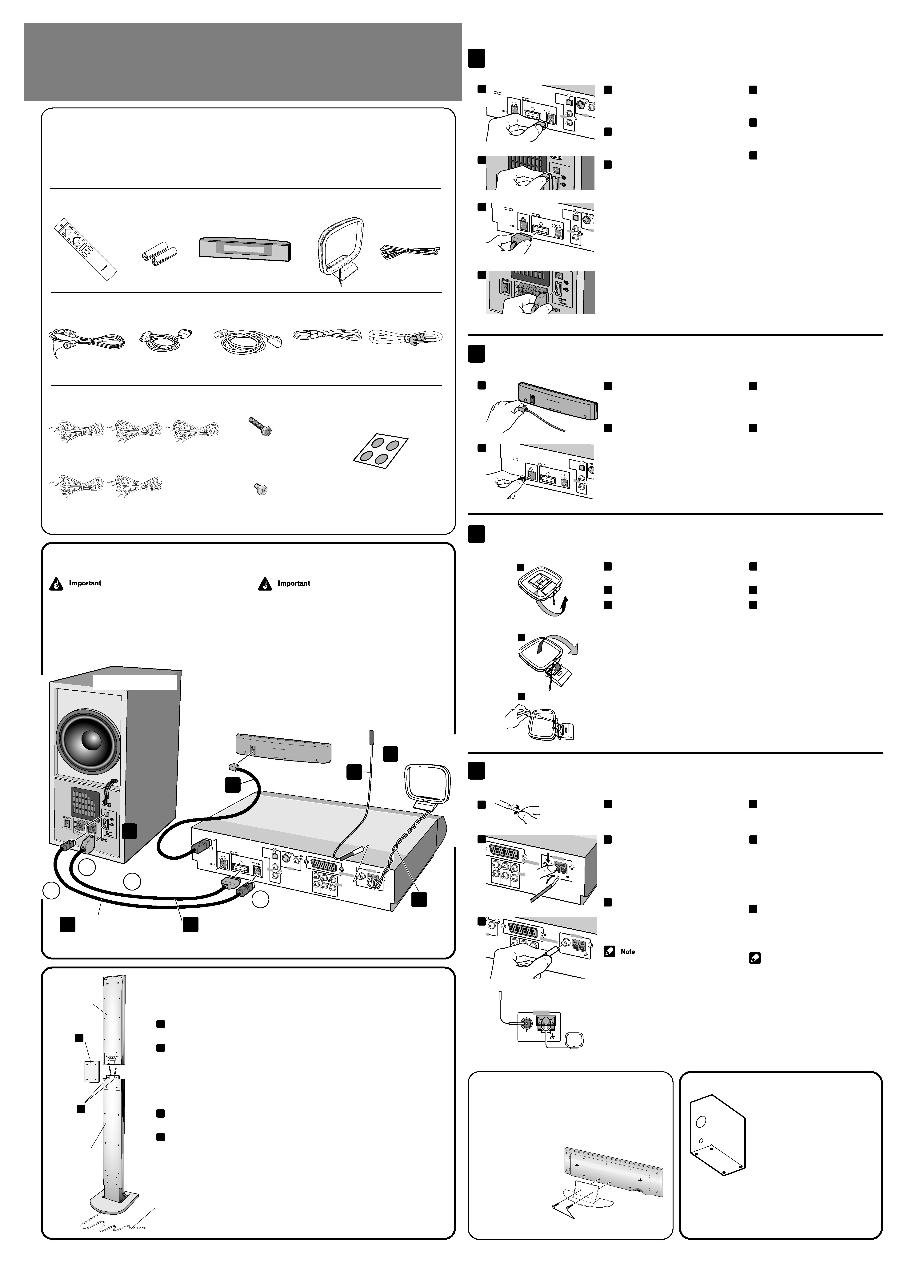
Connect the subwoofer unit to the DVD/CD tuner system
Branchez le caisson de basses au tuner DVD/CD
a
Plug the control cable A (blue
plugs) into the A jack on the
rear of the DVD/CD tuner
system.
b
Plug the other end of the cable
into the A jack on the rear of
the powered subwoofer unit.
c
In the same way, plug one end
of the control cable B (black
plugs) into the B jack on the
rear of the DVD/CD tuner
system, and the other end into
the B jack on the powered
subwoofer unit.
Connect the DVD/CD tuner system to the display unit
Branchement du tuner DVD/CD au display
a
Plug the L-shaped end of the
display cable into the connector
on the rear of the display unit
(AXX7163).
b
Plug the other end of the display
cable into USE ONLY WITH
AXX7163 jack on the DVD/CD
tuner system.
Assemble the AM loop antenna
Montage de l'antenne cadre AM
a
Bend the stand in the direction
indicated by the arrow.
b
Clip the loop onto the stand.
c
If you want to fix to a wall or
other surface, perform step b
after first securing the stand
with screws.
It is recommended that you
determine the reception strength
before securing the stand with the
screws.
a
b
c
Connect the AM and FM antennas
Branchement des antennes AM et FM
a
Twist off the plastic insulation
on the end of each strand of the
AM antenna.
b
Connect one wire of the AM
loop antenna to each AM
antenna terminal.
For each terminal, press down on
the tab to open; insert the wire,
then release to secure.
c
Push the FM antenna plug onto
the center pin of the FM antenna
socket.
· Keep antenna cables away from other
cables, the display unit and main unit.
· To ensure optimum reception, make sure
the FM antenna is fully extended and not
coiled or hanging at the rear of the unit.
· If reception with the supplied antenna is
poor, see
page 73 of the main Operating
instructions, Connecting external
antennas.
ID NO.
ANC82
19
BC-HT017
01A
USE ON
LY
WTTH A
XX7163
USE ONL
Y WITH
OPTICA
L
DIGITAL
IN
B
S-DV700S
W
S-VIDE
O
OUT
A
L
R
LINE1
LINE1
OUT
AUDIO
VIDEO
ID NO.
ANC821
9
BC-HT01
701A
USE ON
LY
WTTH A
XX7163
USE ON
LY WITH
OPTICA
L
DIGITAL
IN
B
S-DV70
0SW
S-VIDE
OUT
A
L
R
LINE1
LINE1
OUT
AUDIO
ANTENNA
FM
UNBAL
75
AM LOOP
ANTENNA
VIDEO
OUT
TV
IN
EO
L
R
AUDIO
LINE1
IN
LINE2
IN
FM
UNBAL
75
AM LOO
P
ANTEN
NA
ANTENNA
AV CONNECT
OR
Non-skid pads
· Stick the four larger pads onto the
base of the subwoofer.
· The subwoofer can be used laying
flat, if you prefer.
Coussinets
antidérapants
· Collez les quatre coussinets les
plus grands sous le caisson de
basses.
· Le caisson de basses peut être
disposé à plat si vous préférez.
a
Branchez le câble pilote A (prises
bleu) dans la prise A à l'arrière
du tuner DVD/CD.
b
Branchez l'autre extrémité du
câble dans la prise A à l'arrière
du caisson de basses asservi.
c
De la même manière, branchez
une extrémité du câble pilote B
(prises noires) dans la prise B à
l'arrière du tuner DVD/CD et
branchez l'autre extrémité dans
la prise B du caisson de basses
asservi.
a
Branchez le côté en équerre du
câble du display dans le
connecteur à l'arrière du display
(AXX7163).
b
Branchez l'autre côté du câble
du display dans la prise USE
ONLY WITH AXX7163 sur le
tuner DVD/CD.
a
Inclinez le pied dans la direction
indiquée par la flèche.
b
Clipsez la boucle dans le pied.
c
Si vous désirez la fixer au mur
ou sur un autre matériau,
veuillez effectuer l'étape b après
avoir fixé le pied à l'aide de vis.
Il est conseillé de déterminer la
réception avant d'assembler le
support avec les vis.
a
Cassez l'isolant plastique à
l'extrémité de chaque brin de
l'antenne AM.
b
Connectez un câble de l'antenne
cadre AM à chaque terminal
d'antenne AM.
Pour chaque terminal, appuyez sur
l'onglet pour ouvrir, insérez le
câble, et relâcher ensuite pour
mettre en place le câble.
c
Poussez la prise de l'antenne FM
dans la broche centrale de la
prise antenne FM.
Remarque
· Eloignez les câbles de l'antenne des
autres câbles, du display et de l'unité
principale.
· Pour assurer une réception, vérifiez que
l'antenne FM est complètement dépliée
et pas enroulée sur elle-même ou qu'elle
ne pend pas à l'arrière de l'appareil.
· Si la réception à l'aide de l'antenne
fournie est mauvaise, voir
page 78 du
Mode d'emploi, Raccordement
d'antennes externes.
ID
ID NO.
NO.
ANC821
9
ANC8219
BC-HT
01701A
BC-HT01701A
USE ON
LY
WTTH
AXX71
63
USE ON
LY WITH
OPTICA
L
DIGITAL
IN
B
S-DV70
0SW
S-VIDEO
OUT
VIDEO
OUT
A
L
R
LINE
1
LINE1
OUT
AUDIO
VIDEO
TV
IN
L
R
AUDIO
LINE1
IN
LINE2
IN
FM
UNBAL
75
AM LOOP
ANTENNA
ANTENN
A
AV CON
NECTOR
FRONT
SURR
OUND
CENTER
R
R
L
L
Check the supplied
accessories
Confirm that the following accessories are in the box
when you open it.
Remote control unit
Boîtier de télécommande
ST+
TUNE+
ENTER
TUN
E
MASTER
VOLUME
ST
ST
ANDBY/ON
CD
TRA
Y
OPEN
CLOSE
DOOR
OPEN
CLOSE
DVD
FM/AM
TV
VIDEO
V1/V2/V3
0
1
4
4
¡
8
3
7
0
DVD
MENU
RETURN
SOUND
TV
CONTROL
PV
O
L
INPUT
MUTE
PROG
RAM
RE
PEA
T
RAN
DOM
AUTO
ROOM
SETUP
TEST
TONE
1
23
DVD
SYSTEM
CH
LEVEL
TC
P
M
ENU
SYS
MENU
DIM
MER
DVD
DISP
SYS
DISP
SET
UP
SURRO
UND
AN
GLE
AUDIO
SUBTITLE
ZOOM
ADV
ANCED
456
789
0
LANGUAGE
MAIN
AX0000
SUB
PCM
TELETEXT
ON/OFF
TIMER
(CLOCK
ADJ
)
FOLDER
CLR
ENTER
/
FOLDER+
Dry cell batteries
(size AA/R6P) x 2
Piles sèches (de
type AA/R6P) x 2
Display unit (AXX7163)
Unité d'affichage (AXX7163)
AM loop antenna
Antenne cadre AM
FM antenna
Antenne FM
Control cable A
Câble de commande A
Control cable B
Câble de commande B
Display cable
Câble de l'unité
d'affichage
Video cord
Cordon vidéo
Gray / Gris
Yellow plugs
Prises jaunes
Blue plugs / Prises
bleues
Power cord
Cordon d'alimentation
Speaker cords / Cordons d'enceintes
5 m x 3 (for center, front L-R speakers)
5 m x 3 (pour enceintes centrale et avant G-D)
Operating instructions / Warranty
Mode d'emploi / Garantie
Vérification des
accessoires fournis
Veuillez vous assurez que les accessoires suivants ont
été livrés avec l'appareil lorsque vous ouvrez son
emballage.
10 m x 2 (for rear L-R speakers)
10 m x 2 (pour enceintes arrières G-D)
Black plugs / Prises
noires
Non-skid pads
(subwoofer) x 4
Coussinets antidérapants
(caisson de basses) x 4
1
2
3
4
a
b
c
c
a
b
a
b
c
Connecting up
When connecting this system or changing connections,
be sure to switch power off and disconnect the power
cord from the wall socket.
After completing all connections, connect the power cord
to the wall socket.
Branchements
Lors du branchement de cet appareil ou du changement
des branchements, vérifiez que l'appareil est débranché
du secteur.
Après avoir terminé tous les branchements, branchez le
cordon d'alimentation au secteur.
ID
ID NO.
NO.
ANC8219
ANC8219
BC-HT01701A
BC-HT01701A
USE ONL
Y
WTTH
AXX7163
USE ONL
Y WITH
OPTICAL
DIGIT
AL
IN
B
S-DV700SW
S-VIDEO
OUT
VIDEO
OUT
A
L
R
LINE1
LINE1
OUT
TV
IN
AUDIO
VIDEO
L
R
AUDIO
LINE1
IN
LINE2
IN
FM
UNBAL
75
AM LOOP
ANTENNA
ANTE
NNA
AV CONN
ECTOR
FRON
T
SURRO
UND
CENTER
R
R
L
L
AM loop antenna
Antenne cadre AM
Display unit (AXX7163)
Unité d'affichage (AXX7163)
DVD/CD tuner system
Combiné radio / DVD/CD
Powered subwoofer unit
Enceinte active d'extrême gave
A
A
B
B
Control cable A (blue plugs)
Câble de commande A (prises bleues)
Control cable B (black plugs)
Câble de commande B (prises noires)
1
3
1
1
Display cable (gray)
Câble de l'unité d'affichage (gris)
2
4
4
Assembly for the front and surround speaker
stands
For each front and surround speaker:
a
Attach the speaker to the stand and secure with two of the larger supplied
screws.
b
Attach the cover plate using four of the smaller supplied screws.
a
b
Large screws x 8
Vis longues x 8
Small screws x 18
Vis courtes x 18
Stand
Support
Speaker
Enceinte
Montage des supports des enceintes avant et
arrière
Pour chaque enceinte avant et arrière:
a
Fixez l'enceinte au support et assurez son maintien au moyen de deux des
vis longues fournies.
b
Fixez le cache au moyen de quatre des vis courtes fournies.
Speaker cord (supplied)
Thread the speaker cord through the base and up through the speaker stand, as shown.
See left for how to connect the speaker cord to the speaker terminals.
Cordon d'enceinte (fourni)
Faites cheminer le cordon à travers la base puis vers le haut du support d'enceinte,
comme le montre l'illustration. Reportez-vous ci-contre à gauche pour connaître la
manière de relier le cordon d'enceinte aux bornes de l'enceinte.
Assembling the stand for the
center speaker
· Use two of the supplied small screws to assemble the stand
as shown in the diagram.
Montage du support de
l'enceinte
centrale
· Utilisez deux des vis
courtes fournies
pour monter le
support comme le
montre l'illustration.
Small screws x 2 (supplied)
Vis courtes x 2 (fournies)
ARE7334A_EN/FR_01_02
03.6.12, 10:10 AM
1
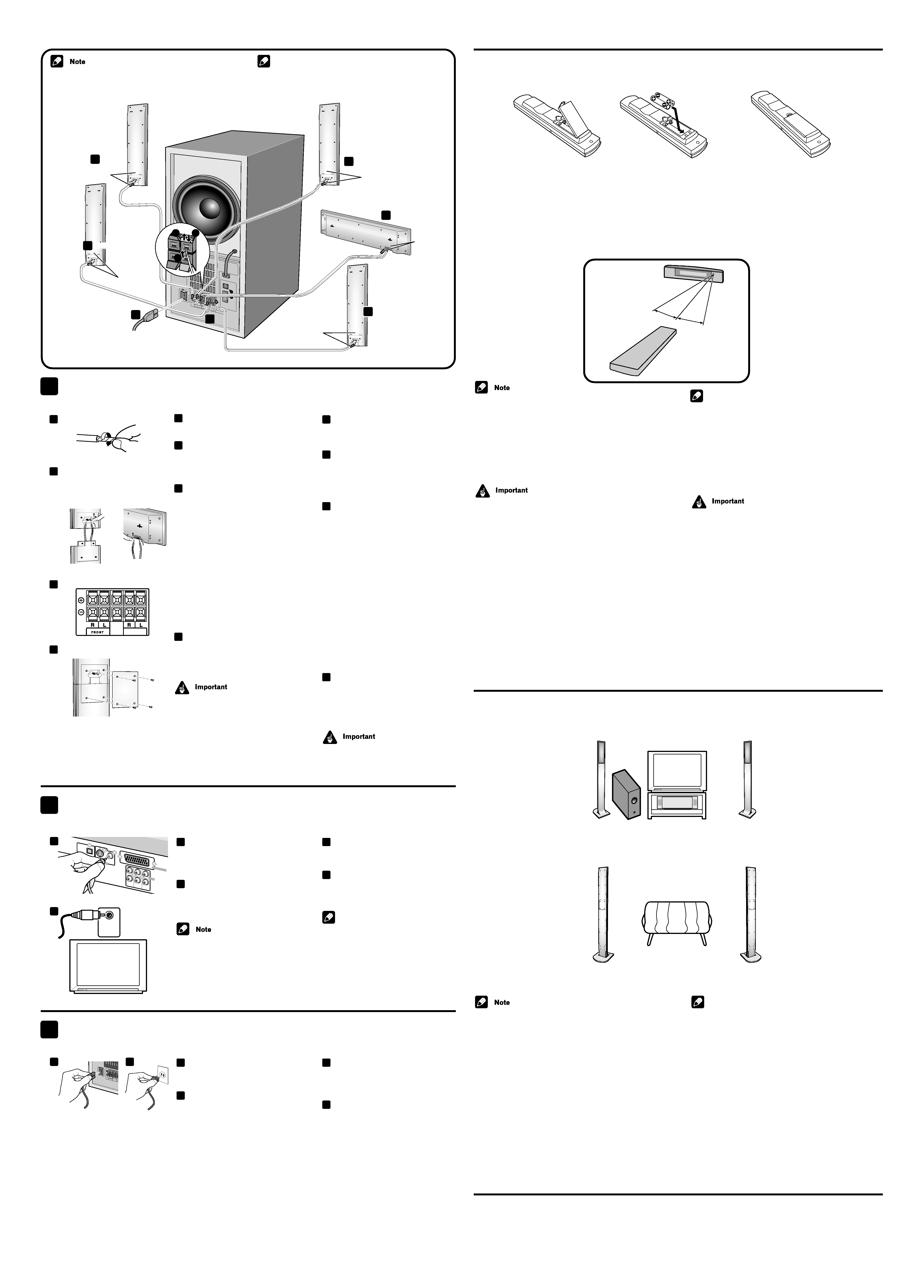
Connect the speakers
Branchement des enceintes
a
Twist and pull off the insulation
on both ends of each speaker
cord.
b
Connect a speaker cord to the
terminals on the rear of each
speaker, attaching the colored
wire to the red terminal and the
other wire to the black terminal.
c
Connect the other end of each
speaker cord to the speaker
terminals on the rear of the
subwoofer.
· Make sure that each speaker is
connected to its correct pair of
speaker terminals.
· Each speaker cord has two wires. For
correct sound, the colored wire
should be connected to the red
terminal; the other wire to the black
terminal.
· Push the speaker terminal tab to
open; insert the exposed wire,
making sure there are no stray
strands. Release the tab to secure the
wire.
d
Fit each speaker on to its stand
and secure using two of the
larger supplied screws, then
attach the cover plate with four
of the smaller screws.
Do not use these speakers with other
amplifiers or systems. Doing so may
result in damage or fire.
Connecting the speaker cords is easier if you first stick
the supplied cord labels on either end of each cord.
Connect the TV
Branchements de la TV
a
Connect the supplied video cord
(yellow plugs) to the VIDEO OUT
jack on the DVD/CD tuner
system.
b
Connect the other end of the
video cord to the TV's VIDEO IN
jack.
Other types of video connection are
possible. See
page 75-77 of the main
Operating Instructions for more
information.
VIDEO
IN
Connect the power cord
Branchement du cordon d'alimentation
a
Connect the power cord to AC
INLET on the powered
subwoofer.
b
Connect the power cord to a
wall socket.
Loading batteries in the
remote control
Insérer les piles dans la
télécommande
Incorrect use of batteries may cause leakage or rupture.
Always be sure to follow these guidelines:
· Always load the batteries matching the positive
ª and
negative
· polarities, as indicated inside the battery
compartment.
· Never mix new and used batteries.
· Batteries of the same size may have different voltages,
depending on brand. Do not
mix different brands of
batteries.
· When disposing of used
batteries, please comply with
governmental regulations or
environmental rules that apply
in your country or area.
The remote control can be
used within a range of about 7
meters from the remote sensor
of the display unit, and within a
30 degree angle.
· To prevent battery leakage, remove the batteries when not
using the remote control for an extended period (one month
or more). If leakage occurs, carefully wipe away any battery
fluid inside the compartment, and replace the batteries with
new ones.
· Do not allow books or other objects to rest on top of the
remote control, since the buttons may be depressed,
shortening the battery life.
· The remote control may not work if there is an obstacle
between the remote control and the display unit, or if the
remote control is not directed towards the remote sensor of
the display unit at the correct angle.
· The remote control may not work properly if strong light such
as direct sunlight or fluorescent light is shining onto the
display unit's remote sensor.
· The remote control may not work properly when this unit is
used near devices emitting infrared rays, or when remote
controls of other devices which use infrared rays are used.
On the other hand, the use of this remote control may cause
other devices to work improperly.
· When the operating range of this remote control becomes
too short, replace the batteries.
Speakers placement
Place speakers as shown below to achieve the optimum
surround sound effect.
Mise en place des enceintes
Placez les enceintes de la manière indiquée ci-dessous afin
d'obtenir un son surround optimal.
· Install the main front left and right speakers at an equal
distance from the TV.
· For best results, install the rear speakers slightly above ear
level.
· This system's speakers are magnetically shielded (JEITA), so
there's virtually no picture color distortion when they are
placed near a TV. In the rare event that there is some picture
color interference, switch power to the TV off, and wait 15 to
30 minutes before switching on again.
· Install the center speaker above or below the TV so that the
sound of the center channel is localized at the TV screen.
· When installing the center speaker on top of the TV, be sure
to secure it with tape or some other suitable means.
Otherwise, the speaker may fall from the TV due to external
shocks such as earthquakes, endangering those nearby or
damaging the speaker.
FRONT
SURR
OUND
CENTER
R
R
L
L
Published by Pioneer Corporation.
Copyright © 2003 Pioneer Corporation.
All rights reserved.
Publié par Pioneer Corporation.
Copyright © 2003 Pioneer Corporation.
Tous droits réservés.
CENTER speaker
Enceinte CENTER
FRONT R speaker
Enceinte FRONT R
FRONT L speaker
Enceinte FRONT L
Subwoofer
Caisson de basses
SURROUND R speaker
Enceinte SURROUND R
SURROUND L speaker
Enceinte SURROUND L
WITH
OPTICAL
DIGIT
AL
IN
S-DV700SW
S-VIDEO
OUT
VIDEO
OUT
A
L
R
LINE1
LINE1
OUT
TV
IN
AUDIO
VIDEO
L
R
AUDIO
LINE1
IN
LINE2
IN
AV CONNECT
OR
Remarque
Le branchement des cordons des enceintes est plus
facile si vous collez les étiquettes fournies aux deux
extrémités de chaque cordon.
a
Torsadez les brins après avoir
retiré un morceau d'isolant aux
deux extrémités du cordon
d'enceinte.
b
Reliez un cordon d'enceinte aux
bornes situées à l'arrière de
chaque enceinte, en veillant à ce
que le conducteur de couleur soit
relié à la borne rouge et l'autre
conducteur à la borne noire.
c
Reliez l'autre extrémité de
chaque cordon d'enceinte aux
bornes d'enceinte situées à
l'arrière du caisson de basses.
· Assurez-vous que chaque enceinte
est bien reliée à la paire de bornes
d'enceinte qui lui correspond.
· Chaque cordon d'enceinte est
composé de deux conducteurs. Pour
que les sons soient correctement
reproduits, le conducteur de couleur
doit être relié à la borne rouge;
l'autre conducteur doit être relié à la
borne noire.
· Appuyez sur la languette de la borne
pour ouvrir cette dernière; introduisez
la partie mise à nu en veillant à ce
qu'aucun brin ne soit en dehors de la
borne. Relâchez la languette pour
assurer le maintien du conducteur.
d
Montez chaque enceinte sur son
support et assurez son maintien
au moyen de deux des vis
longues fournies; cela fait fixez le
cache au moyen de quatre vis
courtes.
N'utilisez pas ces enceintes avec
d'autres amplificateurs ou appareils.
Vous risqueriez d'endommager l'appareil
ou de provoquer un court-circuit.
a
Branchez le câble vidéo fourni
(prises jaunes) à la sortie VIDEO
OUT sur le tuner DVD/CD.
b
Branchez l'autre extrémité du
cordon vidéo à la prise VIDEO IN
du TV.
Remarque
Il est possible d'effectuer d'autres types
de branchements vidéo. Veuillez vous
reporter à la
page 80-82 du Mode
d'emploi pour plus d'informations à ce
sujet.
a
Branchez le cordon
d'alimentation à la AC INLET du
caisson de basses sous
alimentation.
b
Branchez le cordon
d'alimentation à une prise
murale.
Les piles peuvent couler ou se casser si elles sont
utilisées de manière incorrecte.
Veuillez toujours suivre ces instructions:
· Insérez toujours les piles en faisant correspondre les
polarités positives
ª et négatives ·, comme indiqué dans
le compartiment des piles.
· Ne mélangez jamais des piles neuves et des piles usées.
· Des piles de même taille peuvent avoir
des tensions différentes, selon la
marque. Ne mélangez pas différentes
marques de piles.
· Lorsque vous jetez des piles usagées,
veuillez vous plier à la législation
gouvernementale et aux règles en
matière d'environnement en vigueur
dans votre pays ou votre région.
La télécommande peut être utilisée
dans un rayon de 7 mètres à partir du
capteur de la télécommande du
display, et jusqu'à un angle de 30
degrés.
· Il se peut que la télécommande ne fonctionne pas si un
obstacle se trouve entre elle et le display, ou si la
télécommande n'est pas dirigée selon un angle correct vers
le capteur de la télécommande sur le display.
· Il se peut que la télécommande ne fonctionne pas
correctement si le capteur de la télécommande sur le display
est exposé à une lumière intense telle que la lumière du
soleil.
· Il se peut que la télécommande ne fonctionne pas
correctement lorsque cet appareil est utilisé à proximité
d'appareils utilisant des rayons à infra-rouges ou pendant
l'utilisation d'autres appareils utilisant des rayons infra-
rouges.
Bien évidemment, l'utilisation de cette télécommande peut
entraîner un dysfonctionnement d'autres appareils.
· Lorsque le rayon d'action de la télécommande devient trop
petit, changez les piles.
Remarque
· Installez les enceintes principales avant gauche et droite à
distance égale du TV.
· Pour obtenir les meilleurs résultats, placez les enceintes
légèrement au-dessus du niveau de vos oreilles en position
d'écoute.
· Les enceintes de cet appareil sont magnétiquement
protégées (JEITA), de manière à ce qu'il n'y ait virtuellement
aucune distorsion de l'image lorsqu'elles sont placées près
d'un TV. Si des interférences surviennent au niveau de la
couleur de l'image, mettez le TV hors tension et attendez de
15 à 30 minutes avant de le rallumer.
· Installez l'enceinte centrale au-dessus ou au-dessous du TV
de manière à ce que le son du canal central soit dirigé vers
l'écran du TV.
· Lors de l'installation de l'enceinte centrale au-dessus du TV,
maintenez-le en place à l'aide de scotch ou autre. Sinon,
l'enceinte pourrait tomber du TV, en cas de chocs extérieurs
tels que tremblements de terre. Elle risquerait de casser ou
de mettre en danger les personnes à proximité.
Batteries / Piles
(AA/R6P) x 2
XV-DV1
000
AAX795
8
Red
Rouge
Grey
Gris
Blue
Bleu
Green
Vert
10m
10m
5m
5m
5m
White
Blanc
FRONT R
5
SUROUND R
5
FRONT L
5
5
7
SURROUND L
5
CENTER
5
1
3
2
7m
30°
30°
Printed in
/ Imprimé au
<ARE7334-A>
<TWKZW/03F00001>
5
6
7
c
a
b
a
b
Remarque
· Pour empêcher les piles de couler, veuillez les enlever
lorsque vous n'utilisez pas la télécommande pendant une
période prolongée (un mois ou plus). Dans le cas d'une fuite,
essuyez avec précaution tout liquide qui a coulé à l'intérieur
du compartiment, et remplacez les piles par de nouvelles.
· Ne posez pas de livres ou autres objets sur la télécommande,
car les boutons pourraient être déprimés, ce qui
raccourcirait la durée de vie de la télécommande.
SURROUND
CENTER
a
b
d
CENTER
Centre
FRONT and
SURROUND
Avant et arrière
ARE7334A_EN/FR_01_02
03.6.12, 10:10 AM
2