ORDER NO.
PIONEER CORPORATION 4-1, Meguro 1-chome, Meguro-ku, Tokyo 153-8654, Japan
PIONEER ELECTRONICS (USA) INC. P.O. Box 1760, Long Beach, CA 90801-1760, U.S.A.
PIONEER EUROPE NV Haven 1087, Keetberglaan 1, 9120 Melsele, Belgium
PIONEER ELECTRONICS ASIACENTRE PTE. LTD. 253 Alexandra Road, #04-01, Singapore 159936
PIONEER CORPORATION 2004
RRV2886
T ZZK FEB. 2004 Printed in Japan
DVD/CD RECEIVER
XV-DV222
Model No.
Order No.
Remarks
XV-DV313/MYXJN
RRV2772
¶ This service manual should be used together with the following manual(s):
THIS MANUAL IS APPLICABLE TO THE FOLLOWING MODEL(S) AND TYPE(S).
¶ For SPECIFICATIONS and PANEL FACILITIES, refer to the operating instructions.
Model
Type
Power Requirement
Region No.
Remarks
XV-DV222
MYXJN
AC220-230V
2
XV-DV222
NVXJN
AC230V
2
2
1
23
4
12
3
4
C
D
F
A
B
E
XV-DV222
1. CONTRAST OF MISCELLANEOUS PARTS
jp
f
y
For the applying amount of lubricants or glue, follow the instructions in this manual.
(In the case of no amount instructions, apply as you think it appropriate.)
Parts marked by "NSP" are generally unavailable because they are not in our Master Spare Parts List.
The
mark found on some component parts indicates the importance of the safety factor of the part.
Therefore, when replacing, be sure to use parts of identical designation.
Screws adjacent to
mark on product are used for disassembly.
Reference Nos. indicate the pages and Nos. in the service manual for the base model.
NOTES:
CONTRAST TABLE
XV-DV222/MYXJN, NVXJN and XV-DV313/MYXJN are constructed the same except for the following :
Part No.
Ref. No. Mark
Symbol and Description
XV-DV313
XV-DV222
XV-DV222
Remarks
/MYXJN
/MYXJN
/NVXJN
PACKING SECTION
P9- 1
Power Cord
ADG1154
ADG1154
ADG1156
P9- 8
Operating Instructions (English)
XRB3023
XRB3039
XRB3039
P9- 9
Operating Instructions Basic (English/French)
XRE3072
XRE3089
XRE3089
P9-10
Operating Instructions Basic (German/Italian)
XRC3101
XRC3165
Not used
P9-11
Operating Instructions Basic (Dutch/Spanish)
XRC3102
XRC3166
Not used
P9-12
Operating Instructions (German)
XRC3084
XRC3167
Not used
P9-13
Operating Instructions (Dutch)
XRC3085
XRC3168
Not used
P9-14
Operating Instructions (French)
XRC3086
XRC3169
Not used
P9-15
Operating Instructions (Italian)
XRC3087
XRC3170
Not used
P9-16
Operating Instructions (Spanish)
XRC3088
XRC3171
Not used
P9-21
Packing Case
XHD3351
XHD3446
XHD3446
EXTERIOR SECTION
P11-24
Rear Panel
XNC3217
XNC3317
XNC3318
P11-47
Tray Cap
XAK3389
XAK3467
XAK3467
P11-50
Name Label
XAX3375
XAX3463
XAX3463
P11-64
Screw
BBZ30P060FMC
BBZ30P060FTC
BBZ30P060FTC
P11-66
Screw
BBZ40P060FMC
BBZ40P060FTC
BBZ40P060FTC
P11-67
Screw
BPZ30P080FZK
BPZ30P080FTC
BPZ30P080FTC
P11-68
Screw
CBZ30P080FMC
CBZ30P080FTC
CBZ30P080FTC
P11-70
Screw
VPZ30P140FMC
VPZ30P140FTC
VPZ30P140FTC
P11-71
Screw
VBZ30P080FMC
VBZ30P080FTC
VBZ30P080FTC
FRONT SECTION
P13- 8
Rubber Cover
XEB3034
Not used
Not used
P13- 9
Display Panel
XAK3408
XAK3468
XAK3468
P13-10
NSP
Front Panel Assy
XXG3160
XXG3193
XXG3193
P13-11
Front Cap
XAK3390
XAK3469
XAK3469
P13-13
Top Panel Assy
XZN3131
XZN3152
XZN3152
P13-15
Screw
VPZ30P080FZK
VPZ30P080FTC
VPZ30P080FTC
P13-17
Screw
PBA1096
XBA3013
XBA3013
ORDER NO.
PIONEER CORPORATION 4-1, Meguro 1-chome, Meguro-ku, Tokyo 153-8654, Japan
PIONEER ELECTRONICS (USA) INC. P.O. Box 1760, Long Beach, CA 90801-1760, U.S.A.
PIONEER EUROPE NV Haven 1087, Keetberglaan 1, 9120 Melsele, Belgium
PIONEER ELECTRONICS ASIACENTRE PTE. LTD. 253 Alexandra Road, #04-01, Singapore 159936
PIONEER CORPORATION 2003
RRV2772
DVD/CD RECEIVER
XV-DV515
T ZZV MAY. 2003 Printed in Japan
XV-DV515
0 OPEN/CLOSE
6
DVD/CD
FM/AM
DOWN
VOLUME
UP+
STANDBY/ON
PHONES
7
7
XV-DV313
Model
Types
Power Requirement
Region No.
Remarks
XV-DV515
MYXJ
AC220-230V
2
XV-DV515
NVXJ
AC230V
2
XV-DV313
MYXJN
AC220V-230V
2
XV-DV313
NVXJN
AC230V
2
THIS MANUAL IS APPLICABLE TO THE FOLLOWING MODEL(S) AND TYPE(S).
For details, refer to "Important symbols for good services" on the next page.
2
1
23
4
12
3
4
C
D
F
A
B
E
XV-DV515
This service manual is intended for qualified service technicians ; it is not meant for the casual do-
it-yourselfer. Qualified technicians have the necessary test equipment and tools, and have been
trained to properly and safely repair complex products such as those covered by this
manual.Improperly performed repairs can adversely affect the safety and reliability of the product
and may void the warranty. If you are not qualified to perform the repair of this product properly and
safely, you should not risk trying to do so and refer the repair to a qualified service technician.
WARNING !
THE AEL (ACCESSIBLE EMISSION LEVEL) OF THE LASER POWER OUTPUT IS LESS THAN CLASS 1
BUT THE LASER COMPONENT IS CAPABLE OF EMITTING RADIATION EXCEEDING THE LIMIT FOR
CLASS 1.
A SPECIALLY INSTRUCTED PERSON SHOULD DO SERVICING OPERATION OF THE APPARATUS.
LASER DIODE CHARACTERISTICS
FOR DVD : MAXIMUM OUTPUT POWER : 5 mW
WAVELENGTH : 650 nm
FOR CD :
MAXIMUM OUTPUT POWER : 7 mW
WAVELENGTH : 780 nm
Additional Laser Caution
: See page 90.
1. Laser Interlock Mechanism
· Loading switch (S101 on the LOAB Assy) is used for interlock
mechanism of the laser.
When this switch turned ON in SW2 (CLOSE) side (OPEN signal is
0V and CLOSE signal is 3.5V), a laser becomes the status which can
completely oscillation.
Furthermore, the laser completely oscillates in the disc judgment and
disc playback.
When player is power ON state and laser diode is not completely
oscillating, 780nm laser diode is always oscillating by half power.
· Laser diode is driving with Q201 (650nm LD) and Q211 (780nm LD)
on the DVDM Assy.
Therefore, when short-circuit between the emitter and collector of these
transistors or the base voltage is supplied for transistors turn on, the
laser oscillates. (failure mode)
· In the test mode
, there is the mode that the laser oscillates except
for the disc judgment and playback. LD ON mode in the test mode
oscillates with the laser forcibly.
The interlock mechanism mentioned above becomes invalid in this
mode.
2. When the cover is open, close viewing through the objective lens with
the naked eye will cause exposure to the laser beam.
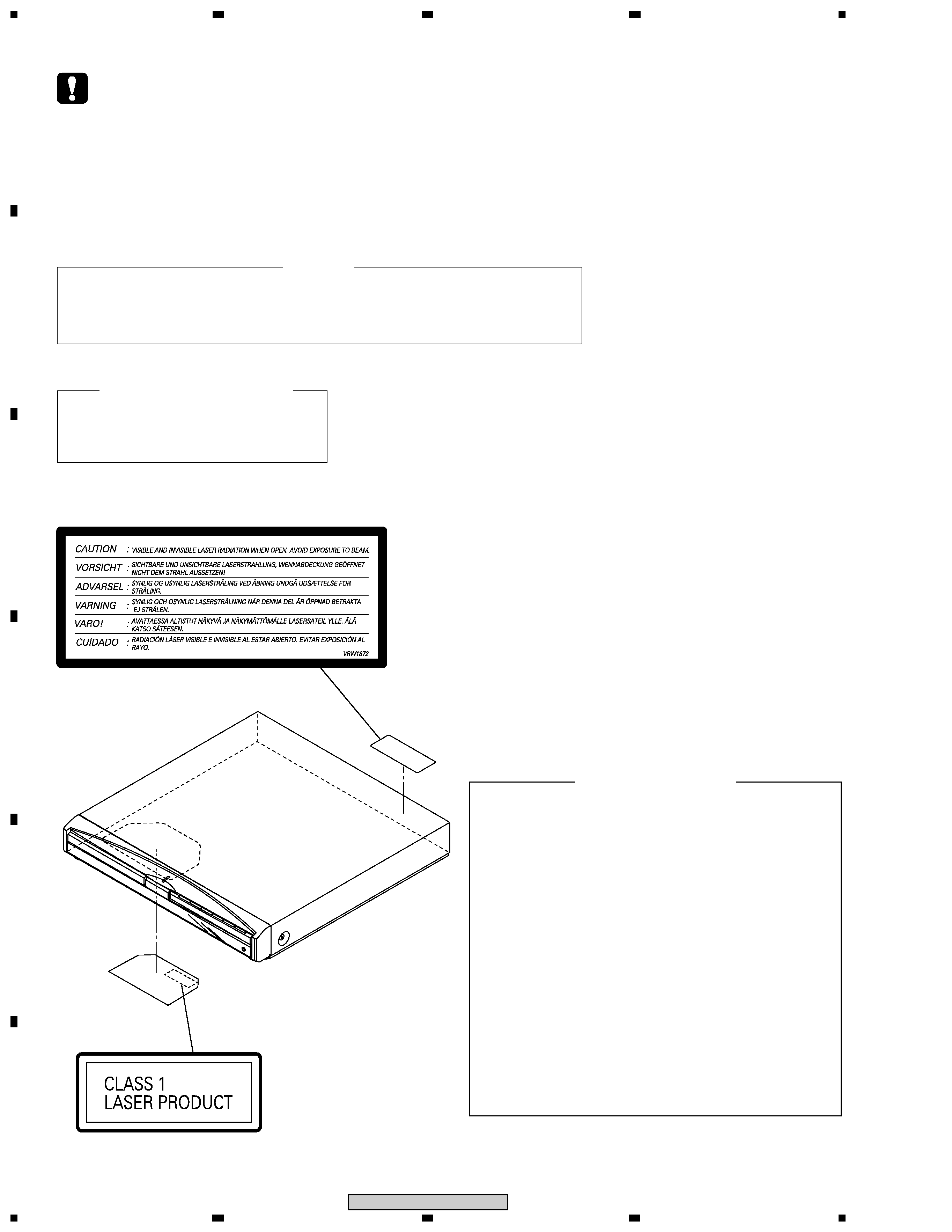
LABEL CHECK
VRW1872
Name Label
SAFETY INFORMATION
3
1
23
4
1
2
3
4
C
D
F
A
B
E
XV-DV515
[ Important symbols for good services ]
In this manual, the symbols shown-below indicate that adjustments, settings or cleaning should be made securely.
When you find the procedures bearing any of the symbols, be sure to fulfill them:
2. Adjustments
To keep the original performances of the product, optimum adjustments or specification confirmation is indispensable.
In accordance with the procedures or instructions described in this manual, adjustments should be performed.
3. Cleaning
For optical pickups, tape-deck heads, lenses and mirrors used in projection monitors, and other parts requiring cleaning,
proper cleaning should be performed to restore their performances.
5. Lubricants, glues, and replacement parts
Appropriately applying grease or glue can maintain the product performances. But improper lubrication or applying
glue may lead to failures or troubles in the product. By following the instructions in this manual, be sure to apply the
prescribed grease or glue to proper portions by the appropriate amount.For replacement parts or tools, the prescribed
ones should be used.
4. Shipping mode and shipping screws
To protect the product from damages or failures that may be caused during transit, the shipping mode should be set or
the shipping screws should be installed before shipping out in accordance with this manual, if necessary.
1. Product safety
You should conform to the regulations governing the product (safety, radio and noise, and other regulations), and
should keep the safety during servicing by following the safety instructions described in this manual.