ORDER NO.
PIONEER CORPORATION 4-1, Meguro 1-chome, Meguro-ku, Tokyo 153-8654, Japan
PIONEER ELECTRONICS SERVICE, INC. P.O. Box 1760, Long Beach, CA 90801-1760, U.S.A.
PIONEER EUROPE NV Haven 1087, Keetberglaan 1, 9120 Melsele, Belgium
PIONEER ELECTRONICS ASIACENTRE PTE. LTD. 253 Alexandra Road, #04-01, Singapore 159936
PIONEER CORPORATION 2000
c
XR-A3800
RRV2356
T ZZE AUG. 2000 Printed in Japan
STEREO CD CASSETTE DECK RECEIVER
1. SAFETY INFORMATION ....................................... 2
2. EXPLODED VIEWS AND PARTS LIST ................. 3
3. BLOCK DIAGRAM AND SCHEMATIC DIAGRAM ... 16
4. PCB CONNECTION DIAGRAM ........................... 32
5. PCB PARTS LIST ................................................ 46
6. ADJUSTMENT ..................................................... 51
CONTENTS
7. GENERAL INFORMATION ................................ 56
7.1 DIAGNOSIS .................................................. 56
7.1.1 DISASSEMBLY .................................... 56
7.2 PARTS .......................................................... 59
7.2.1 IC .......................................................... 59
7.2.2 DISPLAY ............................................... 61
8. PANEL FACILITIES AND SPECIFICATIONS .... 63
THIS MANUAL IS APPLICABLE TO THE FOLLOWING MODEL(S) AND TYPE(S).
Type
Model
XR-A3800
Power Requirement
Remarks
KUCXJ
AC120V
full logic aut reverse
stereo double cassette deck
auto synchro egiting system
W2-2001
REPEAT
SURROUND MODE
DISPLAY MODE
PHONES
2
XR-A3800
1. SAFETY INFORMATION
This service manual is intended for qualified service technicians ; it is not meant for the casual do-it-
yourselfer. Qualified technicians have the necessary test equipment and tools, and have been trained
to properly and safely repair complex products such as those covered by this manual.
Improperly performed repairs can adversely affect the safety and reliability of the product and may
void the warranty. If you are not qualified to perform the repair of this product properly and safely, you
should not risk trying to do so and refer the repair to a qualified service technician.
WARNING
This product contains lead in solder and certain electrical parts contain chemicals which are known to the state of California to cause
cancer, birth defects or other reproductive harm.
Health & Safety Code Section 25249.6 Proposition 65
NOTICE
(FOR CANADIAN MODEL ONLY)
Fuse symbols
(fast operating fuse) and/or
(slow operating fuse) on PCB indicate that replacement parts must
be of identical designation.
REMARQUE
(POUR MODÈLE CANADIEN SEULEMENT)
Les symboles de fusible
(fusible de type rapide) et/ou
(fusible de type lent) sur CCI indiquent que les pièces
de remplacement doivent avoir la même désignation.
ANY MEASUREMENTS NOT WITHIN THE LIMITS
OUTLINED ABOVE ARE INDICATIVE OF A POTENTIAL
SHOCK HAZARD AND MUST BE CORRECTED BEFORE
RETURNING THE APPLIANCE TO THE CUSTOMER.
2. PRODUCT SAFETY NOTICE
Many electrical and mechanical parts in the appliance
have special safety related characteristics. These are
often not evident from visual inspection nor the protection
afforded by them necessarily can be obtained by using
replacement components rated for voltage, wattage, etc.
Replacement parts which have these special safety
characteristics are identified in this Service Manual.
Electrical components having such features are identified
by marking with a
on the schematics and on the parts list
in this Service Manual.
The use of a substitute replacement component which does
not have the same safety characteristics as the PIONEER
recommended replacement one, shown in the parts list in
this Service Manual, may create shock, fire, or other hazards.
Product Safety is continuously under review and new
instructions are issued from time to time. For the latest
information, always consult the current PIONEER Service
Manual. A subscription to, or additional copies of, PIONEER
Service Manual may be obtained at a nominal charge from
PIONEER.
1. SAFETY PRECAUTIONS
The following check should be performed for the
continued protection of the customer and service
technician.
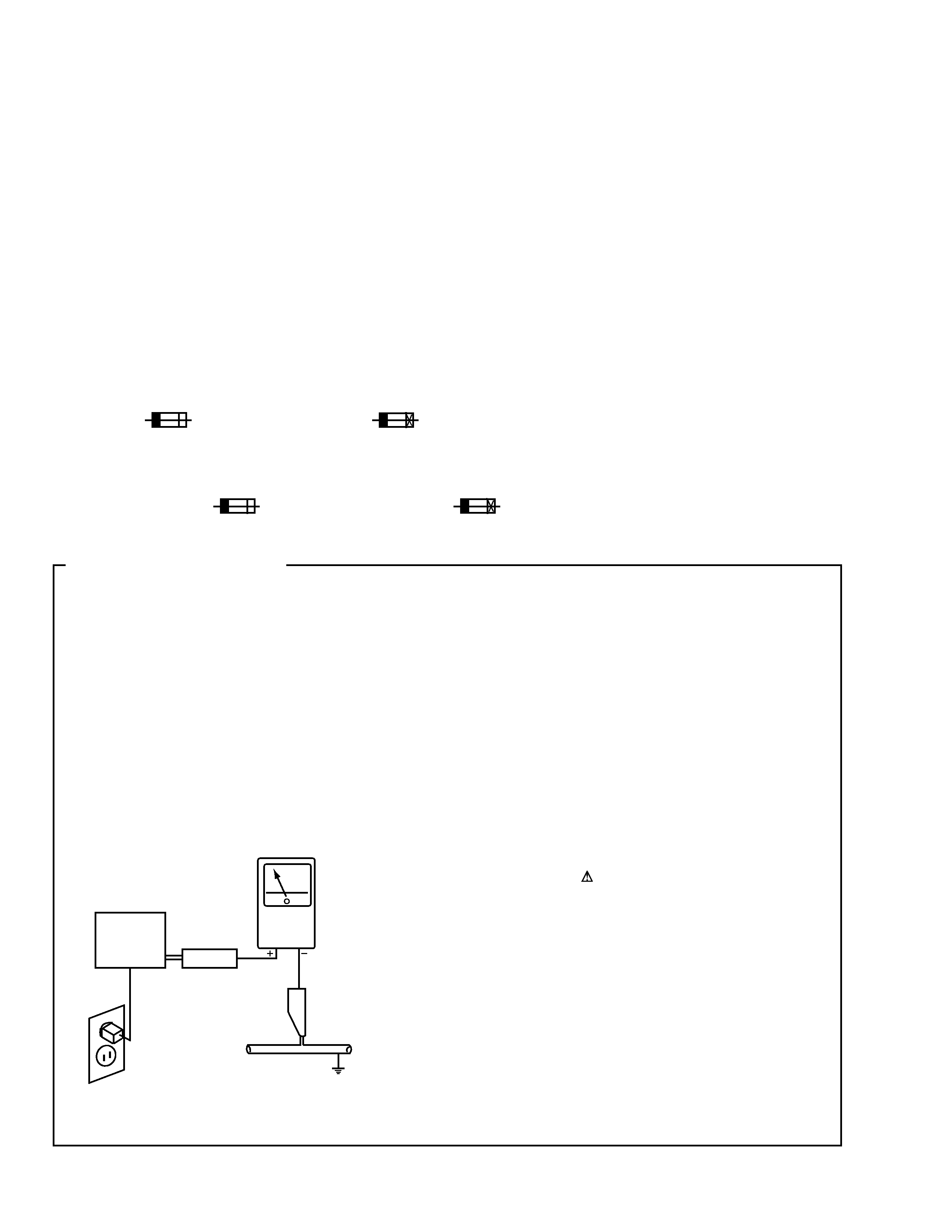
LEAKAGE CURRENT CHECK
Measure leakage current to a known earth ground (water
pipe, conduit, etc.) by connecting a leakage current tester
such as Simpson Model 229-2 or equivalent between the
earth ground and all exposed metal parts of the appliance
(input/output terminals, screwheads, metal overlays, control
shaft, etc.). Plug the AC line cord of the appliance directly
into a 120V AC 60Hz outlet and turn the AC power switch
on. Any current measured must not exceed 0.5mA.
(FOR USA MODEL ONLY)
Leakage
current
tester
Reading should
not be above
0.5mA
Device
under
test
Test all
exposed metal
surfaces
Also test with
plug reversed
(Using AC adapter
plug as required)
Earth
ground
AC Leakage Test
3
XR-A3800
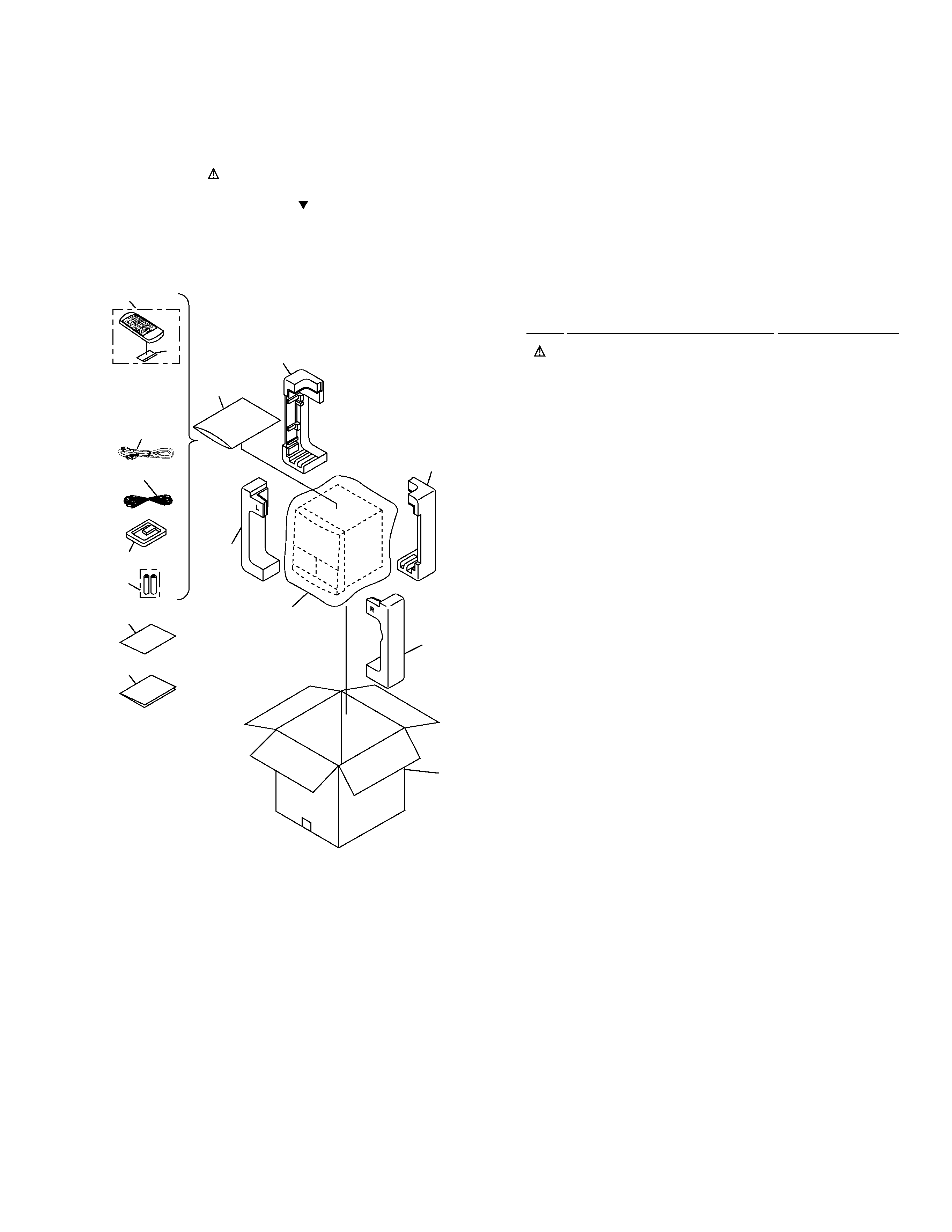
2.1 PACKING
2. EXPLODED VIEWS AND PARTS LIST
NOTES:
· Parts marked by "NSP" are generally unavailable because they are not in our Master Spare Parts List.
· The mark found on some component parts indicates the importance of the safety factor of the part.
Therefore, when replacing, be sure to use parts of identical designation.
· Screws adjacent to mark on the product are used for disassembly.
1
Power Cord
ADG7022
2
FM Antenna
ADH7004
3
AM Loop Antenna
XTB3001
4
Remote Control Unit
XZN3106
5
Battery Cover
XZN3103
NSP
6
Dry Cell Battery (R6P, AA)
VEM-013
7
Packing Sheet
AHG7053
8
Front Pad
XHA3018
9
Rear Pad
XHA3019
10
Packing Case
XHD3118
NSP
11
Warranty Card
ARY7045
12
Polyethylene Bag
Z21-038
(0.03
× 230 × 340)
13
Operating Instructions
XRE3031
(English/French)
· PACKING PARTS LIST
Mark No.
Description
Part No.
VO
L
KA
RA
OK
E
SF
C
DIS
C
DISC
DIS
C
CL
EAR
ST
AT
IO
N
RE
M
OT
E
CO
NT
RO
L
UN
IT
CU
-X
R0
25
M
ONO
BA
ND
PG
M
RE
PE
AT
RA
ND
O
M
AU
X
P.B
AS
S
DIS
PL
AY
SL
EE
P
PO
W
ER
2
3
12
8(1/2)
7
9(1/2)
1
13
11
4
9(2/2)
10
8(2/2)
5
6
4
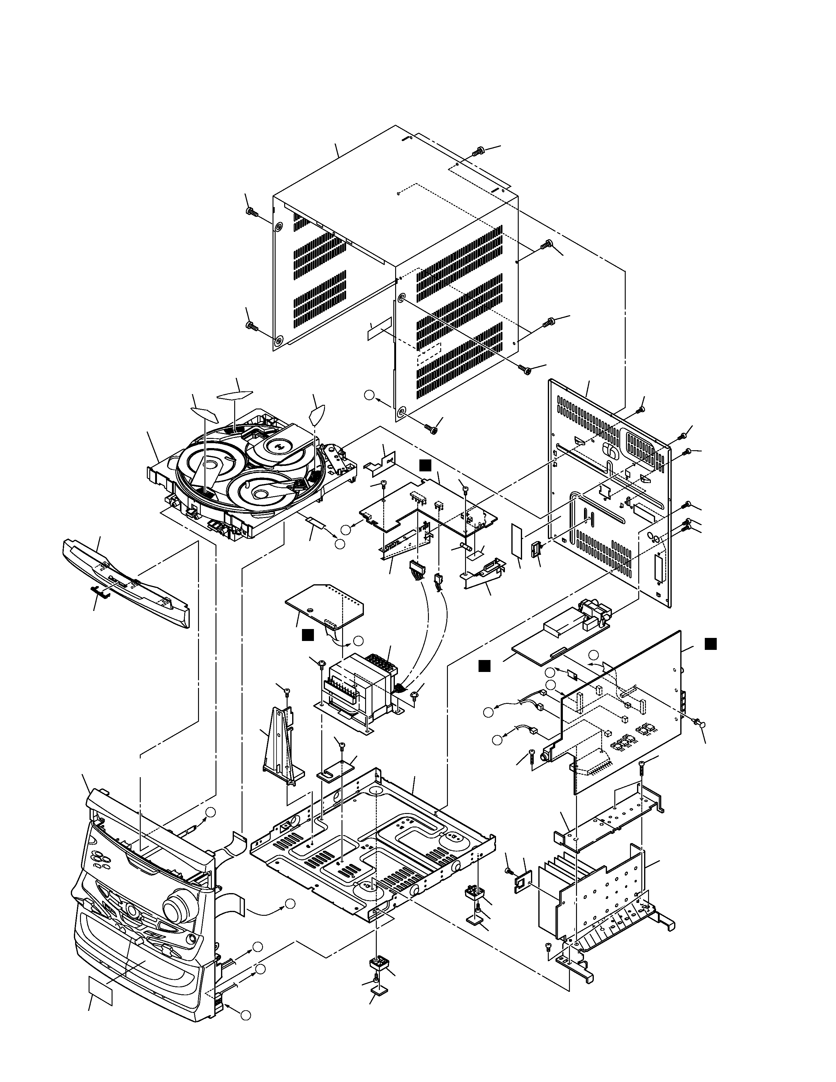
XR-A3800
2.2 EXTERIOR SECTION
B
C
D
G
A
F
C
D
B
E
A
F
E
G
28
46
46
46
46
45
45
43
45
45
46
45
45
32 (1/3)
9
5
Refer to
"2.4 $M MECHANISM CD-2".
Refer to
"2.3 FRONT PANEL SECTION".
27
26
36
32 (2/3)
32 (3/3)
21
24
21
Note :
Hook Tray cap on top of loading
tray and then insert the bottom
three hooks.
Note :
Hook Tray cap on top of loading
tray and then insert the bottom
three hooks.
24
14
16
13
22
15
4
3
8
38
19
18
23
1
37
7
2
25
39
39
41
39
42
41
39
40
40
48
44
39
39
29
43
F
H
G
A
47

5
XR-A3800
1
AF Assy
XWZ3288
2
SECONDARY Assy
XWZ3289
3
PRIMARY Assy
XWZ3296
4
FM/AM TUNER Module
AXQ7065
NSP
5
$M MECHANISM CD-2
XXA3009
6
· · · · ·
7
Power Transformer (T1)
XTS3041
8
Fuse (FU1: 5A)
REK1083
9
Flexible Cable (08P)
XDD3048
10
· · · · ·
11
· · · · ·
12
· · · · ·
13
PCB Bracket
ANG7263
NSP
14
Chassis
XNA3005
15
Rear Panel
XNC3054
16
PCB Bracket
XNG3006
17
· · · · ·
18
Heat Sink
XNH3009
19
Sub Heat Sink B
XNH3012
20
· · · · ·
21
Cushion Leg A
XEB3008
22
Wire Clip A
XEC3003
23
Card Spacer
XEC3008
24
Leg
XMR3012
25
SEC Holder A
XMR3034
· EXTERIOR SECTION PARTS LIST
Mark No.
Description
Part No.
Mark No.
Description
Part No.
26
Tray Cap Assy
XAK3156
27
Pioneer Badge
XAM3001
28
Bonnet Case
XZN3098
NSP
29
Fuse Card
AAX7097
30
· · · · ·
31
· · · · ·
32
Disc Label
XAX3127
33
· · · · ·
34
· · · · ·
35
· · · · ·
NSP
36
Getter
XAX3164
NSP
37
DO NOT THROW Assy
· · · · ·
NSP
38
CABLE HOLDER Assy
· · · · ·
39
Screw
BBZ30P080FMC
40
Screw
BBZ30P180FMC
41
Screw
ASZ40P060FMC
42
Screw
BPZ30P080FMC
43
Screw
VBZ30P080FZK
44
Barier
XEC3013
45
Screw
BPZ30P100FZK
46
Screw
VBT30P080FZK
47
65 Label
ARW7050
48
Fuse Caution Label
XAX3204