ORDER NO.
PIONEER ELECTRONIC CORPORATION 4-1, Meguro 1-Chome, Meguro-ku, Tokyo 153-8654, Japan
PIONEER ELECTRONICS SERVICE, INC. P.O. Box 1760, Long Beach, CA 90801-1760, U.S.A.
PIONEER ELECTRONIC (EUROPE) N.V. Haven 1087, Keetberglaan 1, 9120 Melsele, Belgium
PIONEER ELECTRONICS ASIACENTRE PTE. LTD. 253 Alexandra Road, #04-01, Singapore 159936
PIONEER ELECTRONIC CORPORATION 1998
RRV2047
CONTENTS
T ZZK OCT. 1998 Printed in Japan
1. SAFETY INFORMATION ...................................... 2
2. EXPLODED VIEWS AND PARTS LIST ................ 3
3. SCHEMATIC DIAGRAM ..................................... 16
4. PCB CONNECTION DIAGRAM .......................... 32
5. PCB PARTS LIST ............................................... 44
6. ADJUSTMENT .................................................... 52
7. GENERAL INFORMATION ............................... 61
7.1 PARTS ......................................................... 61
7.1.1 IC ......................................................... 61
7.1.2 DISPLAY .............................................. 68
7.2 DISASSEMBLY ........................................... 72
7.3 BLOCK DIAGRAM ....................................... 76
8. PANEL FACILITIES AND SPECIFICATIONS .... 78
STEREO CD CASSETTE DECK RECEIVER
XR-A660
XR-A550
XR-A330
Type
Model
Power Requirement
Remarks
XR-A660
XR-A550
XR-A330
MYXK
AC220-230V
NVXK
AC230V
MYXJ
AC220-230V
NVXJ
AC230V
THIS MANUAL IS APPLICABLE TO THE FOLLOWING MODEL(S) AND TYPE(S).
XR-A660
2
XR-A660, XR-A550, XR-A330
Printed on the Rear Panel
NVXJ Type
NVXK Type
MYXK and MYXJ Types
MYXK Type
(XR-A550)
(XR-A330)
(XR-A660)
MYXJ Type
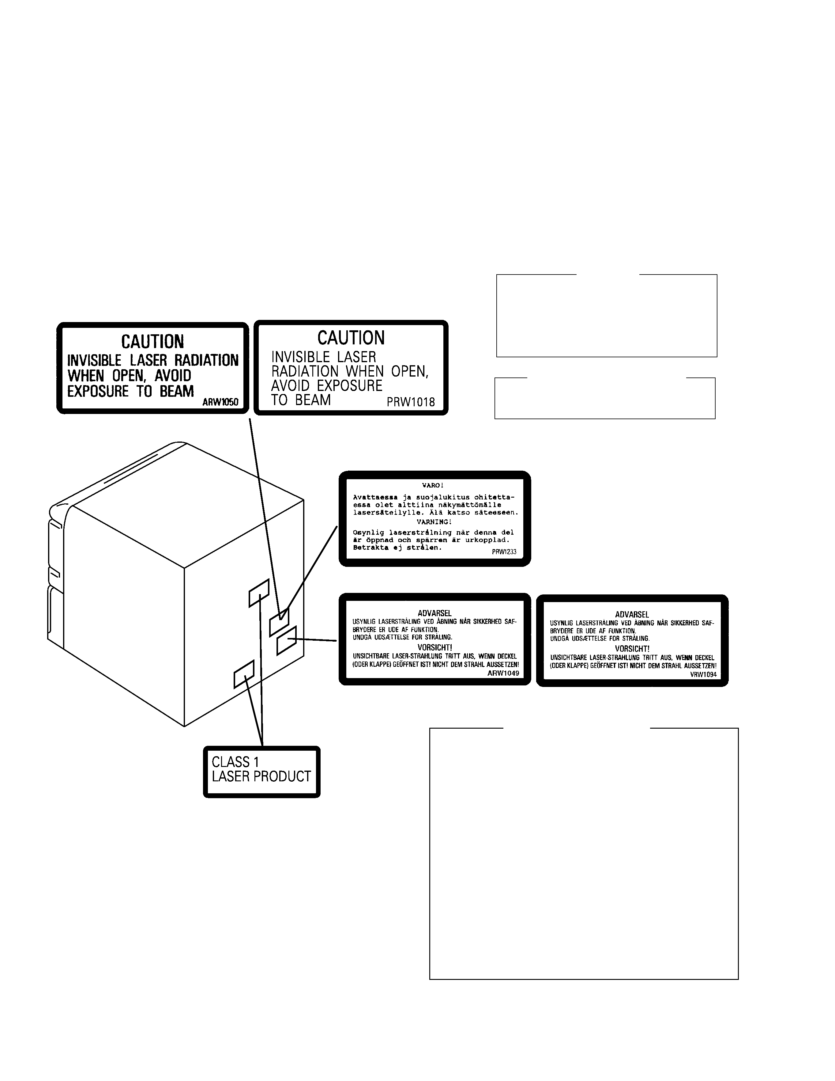
LABEL CHECK
Additional Laser Caution
1. Laser Interlock Mechanism
The position of the switch (S8501) for detecting loading
state is detected by the system microprocessor, and
the design prevents laser diode oscillation when the
switch (S8501) is pressed physically.
Thus, the interlock will no longer function if the switch (S8501)
is released physically and deliberatery.
The interlock also does not function in the test mode
.
Laser diode oscillation will continue, if pin 62 of
LA9240ML (IC8101) on the CD ASSY mounted on the
$M Loading Mechanism assembly is connected to GND,
or else the terminals of Q8101 are shorted to each other
(fault condition).
2. When the cover is opened, close viewing of the objective
lens with the naked eye will cause exposure to a Class
1 laser beam.
: Refer to page 60.
1. SAFETY INFORMATION
This service manual is intended for qualified service technicians ; it is not meant for the casual do-it-
yourselfer. Qualified technicians have the necessary test equipment and tools, and have been trained
to properly and safely repair complex products such as those covered by this manual.
Improperly performed repairs can adversely affect the safety and reliability of the product and may
void the warranty. If you are not qualified to perform the repair of this product properly and safely, you
should not risk trying to do so and refer the repair to a qualified service technician.
IMPORTANT
THIS PIONEER APPARATUS CONTAINS
LASER OF CLASS 1.
SERVICING OPERATION OF THE APPARATUS
SHOULD BE DONE BY A SPECIALLY
INSTRUCTED PERSON.
LASER DIODE CHARACTERISTICS
MAXIMUM OUTPUT POWER: 1.3 mW
WAVELENGTH: 790 nm
± 25 nm
3
XR-A660, XR-A550, XR-A330
k
r
a
M.
o
Nn
o
i
t
p
i
r
c
s
e
D
d
n
a
l
o
b
m
y
S
.
o
N
t
r
a
P
s
k
r
a
m
e
R
0
6
6
A
-
R
X
K
X
Y
M
/
0
6
6
A
-
R
X
K
X
V
N
/
0
5
5
A
-
R
X
J
X
Y
M
/
0
5
5
A
-
R
X
J
X
V
N
/
0
3
3
A
-
R
X
J
X
Y
M
/
0
3
3
A
-
R
X
J
X
V
N
/
3a
n
n
e
t
n
A
p
o
o
L
M
A7
0
0
7
B
T
A7
0
0
7
B
T
A1
0
0
3
B
T
X1
0
0
3
B
T
X1
0
0
3
B
T
X1
0
0
3
B
T
X
P
S
N6
)
A
A
,
P
6
R
(
y
r
e
t
t
a
B
ll
e
C
y
r
D1
0
0
7
X
E
A1
0
0
7
X
E
A3
1
0
-
M
E
V3
1
0
-
M
E
V3
1
0
-
M
E
V3
1
0
-
M
E
V
P
S
N7
g
a
B
e
r
u
t
a
r
e
t
i
L1
9
0
1
G
H
A1
9
0
1
G
H
Ad
e
s
u
t
o
Nd
e
s
u
t
o
Nd
e
s
u
t
o
Nd
e
s
u
t
o
N
73
0
.
0
(
g
a
B
g
o
l
a
t
a
C
×
0
3
2
×
)
0
4
3d
e
s
u
t
o
Nd
e
s
u
t
o
N8
3
0
-
1
2
Z8
3
0
-
1
2
Z8
3
0
-
1
2
Z8
3
0
-
1
2
Z
8d
a
P
t
n
o
r
F7
0
0
3
A
H
X7
0
0
3
A
H
X3
0
0
3
A
H
X7
0
0
3
A
H
X3
0
0
3
A
H
X7
0
0
3
A
H
X
9d
a
P
r
a
e
R8
0
0
3
A
H
X8
0
0
3
A
H
X4
0
0
3
A
H
X8
0
0
3
A
H
X4
0
0
3
A
H
X8
0
0
3
A
H
X
0
1e
s
a
C
g
n
i
k
c
a
P6
4
0
3
D
H
X6
4
0
3
D
H
X3
5
0
3
D
H
X1
7
0
3
D
H
X4
6
0
3
D
H
X9
6
0
3
D
H
X
2
1)
A
5
T
(
e
s
u
Fd
e
s
u
t
o
N1
0
0
7
K
E
Ad
e
s
u
t
o
N6
4
0
1
K
E
Ad
e
s
u
t
o
N6
4
0
1
K
E
A
3
1d
r
o
C
r
e
w
o
P0
1
0
7
G
D
A9
0
0
7
G
D
A4
5
1
1
G
D
A6
5
1
1
G
D
A4
5
1
1
G
D
A6
5
1
1
G
D
A
P
S
N4
1g
a
B
e
n
e
l
y
h
t
e
y
l
o
P3
3
0
7
G
H
Ad
e
s
u
t
o
N3
3
0
7
G
H
Ad
e
s
u
t
o
N3
3
0
7
G
H
Ad
e
s
u
t
o
N
8
1s
n
o
i
t
c
u
r
t
s
n
I
g
n
i
t
a
r
e
p
O3
0
0
3
C
R
Xd
e
s
u
t
o
N3
0
0
3
C
R
Xd
e
s
u
t
o
N3
0
0
3
C
R
Xd
e
s
u
t
o
N
)
h
c
t
u
D
/
n
a
m
r
e
G
/
n
a
il
a
t
I
(
9
1s
n
o
i
t
c
u
r
t
s
n
I
g
n
i
t
a
r
e
p
O4
0
0
3
C
R
Xd
e
s
u
t
o
N4
0
0
3
C
R
Xd
e
s
u
t
o
N4
0
0
3
C
R
Xd
e
s
u
t
o
N
)
h
s
i
n
a
p
S
/
h
s
i
d
e
w
S
/
e
s
e
u
g
u
t
r
o
P
(
VOL
KA
RA
OK
E
SF
C
DISC
DISC
DISC
CLEAR
ST
ATIO
N
REMOTE
CONTROL
UNIT
CU-XR025
MONO
BAND
PGM
RE
PE
AT
RA
ND
O
M
AU
X
P.B
AS
S
DIS
PLA
Y
SL
EE
P
POWER
1
3
MYXK and MYXJ
Types Only
MYXK and MYXJ
Types Only
NVXK and NVXJ
Types Only
7
8(1/2)
11
16
9(1/2)
13
17
4
9(2/2)
9
10
8(2/2)
5
12
2
13
14
18
19
6
MYXJ Type Only
MYXJ Type Only
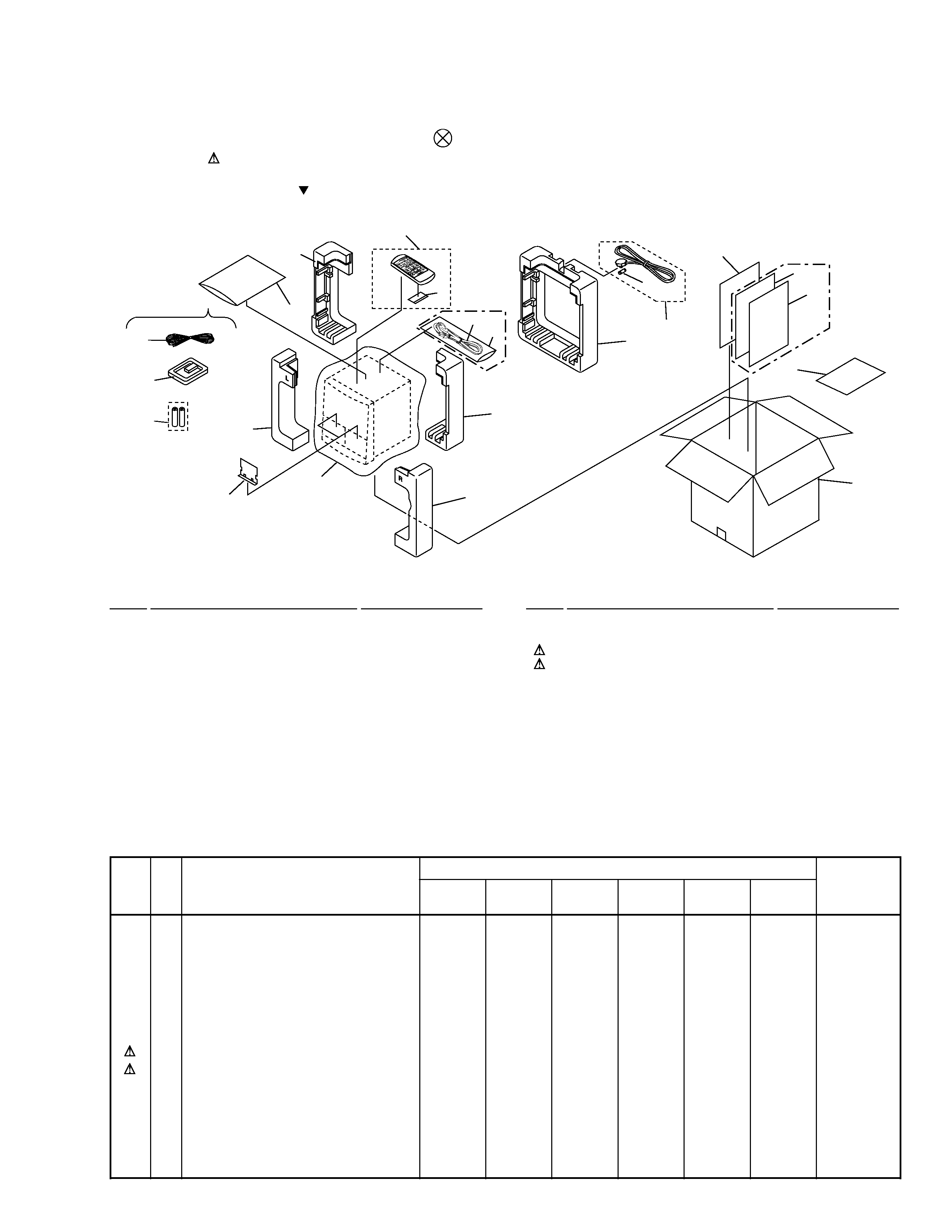
2.1 PACKING
1
FM Antenna
ADH7005
2
Operating Instructions
XRE3014
(English/French)
3
AM Loop Antenna
See Contrast table (2)
4
Remote Control Unit
XZN3006
(CU-XR048)
5
Battery Cover
AZA7204
NSP
6
Dry Cell Battery (R6P, AA)
See Contrast table (2)
NSP
7
Literature Bag
See Contrast table (2)
8
Front Pad
See Contrast table (2)
9
Rear Pad
See Contrast table (2)
(1) PACKING PARTS LIST
Mark No.
Description
Part No.
2. EXPLODED VIEWS AND PARTS LIST
NOTES:
· Parts marked by "NSP" and
can not be supplied.
· The mark found on some component parts indicates the importance of the safety factor of the part.
Therefore, when replacing, be sure to use parts of identical designation.
· Screws adjacent to mark on the product are used for disassembly.
10
Packing Case
See Contrast table (2)
11
Packing Sheet
AHG7049
12
Fuse (T5A)
See Contrast table (2)
13
Power Cord
See Contrast table (2)
NSP
14
Polyethylene Bag
See Contrast table (2)
15
· · · · ·
NSP
16
Door Spacer
XHG3002
NSP
17
Warranty Card
ARY7022
18
Operating Instructions
See Contrast table (2)
19
Operating Instructions
See Contrast table (2)
Mark No.
Description
Part No.
(2) CONTRAST TABLE
XR-A660/MYXK, NVXK, XR-A550/MYXJ, NVXJ, XR-A330/MYXJ and NVXJ are constructed the same except for the
following :
4
XR-A660, XR-A550, XR-A330
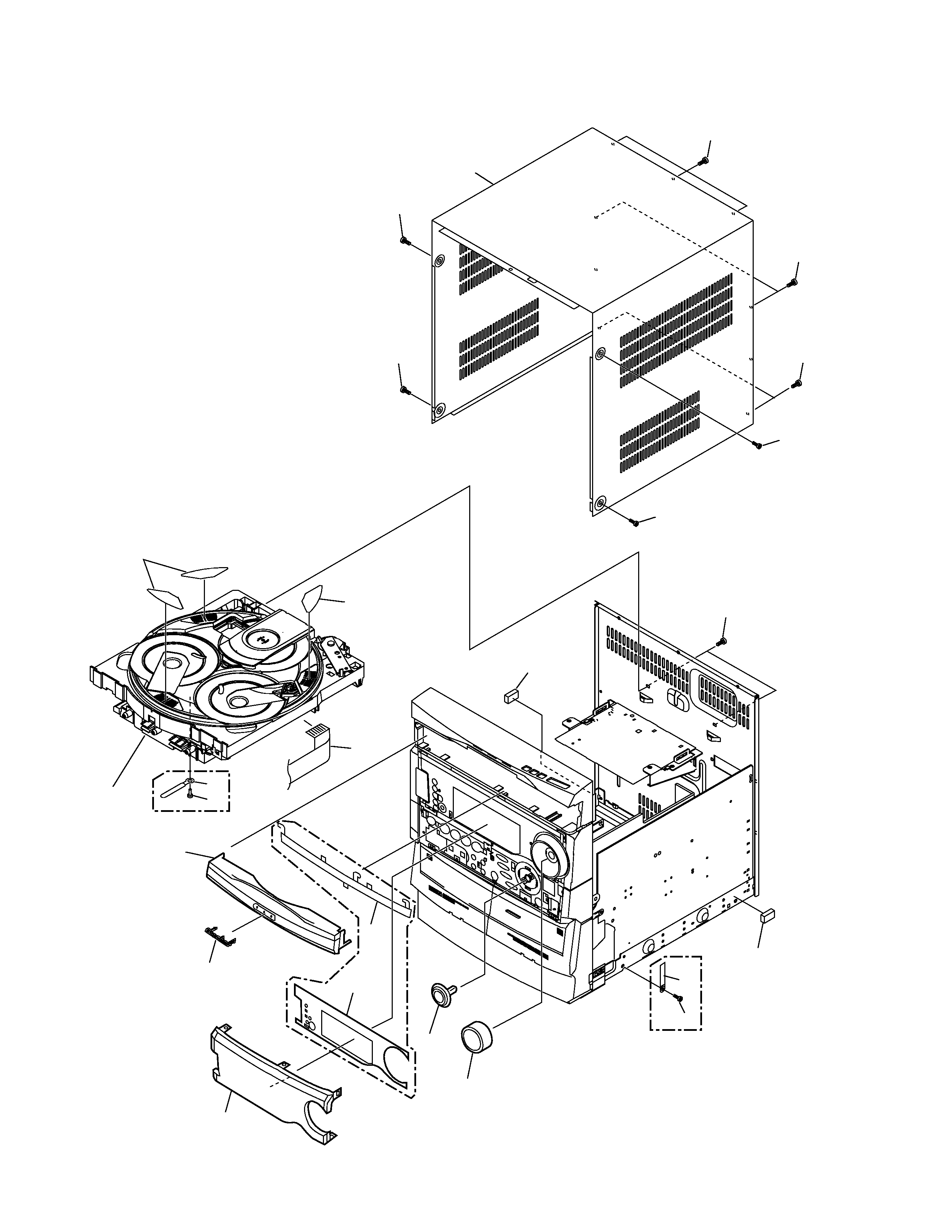
2.2 EXTERIOR (1/2)
13, 14
3
19
20
9
5
4
6
10
2
12
Note :
Attatch on the same numbers
× three.
12
Refer to
"2.5 $M MECHANISM CD".
7
Note :
Hook Tray cap on top of loading tray and then
insert the bottom three hooks.
8
9
9
11
11
15
18
11
15
1
17
16
XR-A660 only
XR-A660 only
XR-A550,
XR-A330
only
19
5
XR-A660, XR-A550, XR-A330
(1) EXTERIOR (1/2) PARTS LIST
Mark No.
Description
Part No.
(2) CONTRAST TABLE
XR-A660/MYXK, NVXK, XR-A550/MYXJ, NVXJ, XR-A330/MYXJ and NVXJ are constructed the same except for the
following :
1
F.F.C/30V
See Contrast table (2)
NSP
2
$M Mechanism CD
See Contrast table (2)
3
Volume Knob
See Contrast table (2)
4
FL Cover A
See Contrast table (2)
5
FL Cover B
See Contrast table (2)
6
Tray Cap
See Contrast table (2)
7
Display Panel
See Contrast table (2)
8
Bonnet Case
See Contrast table (2)
9
Screw
BPZ30P100FZK
10
Pioneer Badge
AZN3049
11
Screw
VBT30P080FZK
12
Disc Label
XAX3127
13
Jog Knob Assy
See Contrast table (2)
14
Jog Knob
See Contrast table (2)
15
Screw
BCZ30P060FZK
16
Cord Clamper
See Contrast table (2)
NSP
17
Cord Stopper
See Contrast table (2)
18
Push Rivet
See Contrast table (2)
19
Cushion Rubber
XEB3002
20
Screw
VBZ30P080FZK
k
r
a
M.
o
Nn
o
i
t
p
i
r
c
s
e
D
d
n
a
l
o
b
m
y
S
.
o
N
t
r
a
P
s
k
r
a
m
e
R
0
6
6
A
-
R
X
K
X
Y
M
/
0
6
6
A
-
R
X
K
X
V
N
/
0
5
5
A
-
R
X
J
X
Y
M
/
0
5
5
A
-
R
X
J
X
V
N
/
0
3
3
A
-
R
X
J
X
Y
M
/
0
3
3
A
-
R
X
J
X
V
N
/
1V
0
3
/
C
.
F
.
F
P
2
28
1
0
3
D
D
X8
1
0
3
D
D
X8
1
0
3
D
D
X8
1
0
3
D
D
Xd
e
s
u
t
o
Nd
e
s
u
t
o
N
1V
0
3
/
C
.
F
.
F
P
0
2d
e
s
u
t
o
Nd
e
s
u
t
o
Nd
e
s
u
t
o
Nd
e
s
u
t
o
N7
1
0
3
D
D
X7
1
0
3
D
D
X
P
S
N2
D
C
m
s
i
n
a
h
c
e
M
M
$6
0
0
3
A
X
X6
0
0
3
A
X
X6
0
0
3
A
X
X6
0
0
3
A
X
X5
0
0
3
A
X
X5
0
0
3
A
X
X
3b
o
n
K
e
m
u
l
o
V5
0
0
3
A
A
X5
0
0
3
A
A
X7
0
0
3
A
A
X7
0
0
3
A
A
X7
0
0
3
A
A
X7
0
0
3
A
A
X
4A
r
e
v
o
C
L
F6
2
0
3
K
A
X6
2
0
3
K
A
Xd
e
s
u
t
o
Nd
e
s
u
t
o
Nd
e
s
u
t
o
Nd
e
s
u
t
o
N
5B
r
e
v
o
C
L
F6
3
0
3
K
A
X6
3
0
3
K
A
Xd
e
s
u
t
o
Nd
e
s
u
t
o
Nd
e
s
u
t
o
Nd
e
s
u
t
o
N
6p
a
C
y
a
r
T7
4
0
3
N
Z
X7
4
0
3
N
Z
X8
4
0
3
N
Z
X8
4
0
3
N
Z
X8
4
0
3
N
Z
X8
4
0
3
N
Z
X
7l
e
n
a
P
y
a
l
p
s
i
D4
5
0
3
K
A
X4
5
0
3
K
A
X1
5
0
3
K
A
X1
5
0
3
K
A
X3
5
0
3
K
A
X3
5
0
3
K
A
X
8e
s
a
C
t
e
n
n
o
B2
6
0
3
N
Z
X2
6
0
3
N
Z
X5
4
0
3
N
Z
X5
4
0
3
N
Z
X5
4
0
3
N
Z
X5
4
0
3
N
Z
X
3
1y
s
s
A
b
o
n
K
g
o
J3
2
0
3
G
X
X3
2
0
3
G
X
Xd
e
s
u
t
o
Nd
e
s
u
t
o
Nd
e
s
u
t
o
Nd
e
s
u
t
o
N
4
1b
o
n
K
g
o
Jd
e
s
u
t
o
Nd
e
s
u
t
o
N8
0
0
3
A
A
X8
0
0
3
A
A
X8
0
0
3
A
A
X8
0
0
3
A
A
X
6
1r
e
p
m
a
l
C
d
r
o
C4
8
1
-
H
N
R4
8
1
-
H
N
Rd
e
s
u
t
o
Nd
e
s
u
t
o
Nd
e
s
u
t
o
Nd
e
s
u
t
o
N
P
S
N7
1r
e
p
p
o
t
S
d
r
o
Cd
e
s
u
t
o
Nd
e
s
u
t
o
N8
2
1
1
F
N
D8
2
1
1
F
N
D8
2
1
1
F
N
D8
2
1
1
F
N
D
8
1t
e
v
i
R
h
s
u
Pd
e
s
u
t
o
Nd
e
s
u
t
o
N8
3
1
7
C
E
A8
3
1
7
C
E
A8
3
1
7
C
E
A8
3
1
7
C
E
A