ORDER NO.
PIONEER CORPORATION 4-1, Meguro 1-chome, Meguro-ku, Tokyo 153-8654, Japan
PIONEER ELECTRONICS SERVICE, INC. P.O. Box 1760, Long Beach, CA 90801-1760, U.S.A.
PIONEER EUROPE NV Haven 1087, Keetberglaan 1, 9120 Melsele, Belgium
PIONEER ELECTRONICS ASIACENTRE PTE. LTD. 253 Alexandra Road, #04-01, Singapore 159936
PIONEER CORPORATION 2000
c
XC-F10
RRV2341
1. SAFETY INFORMATION ...................................... 2
2. EXPLODED VIEWS AND PARTS LIST ............... 3
3. BLOCK DIAGRAM AND SCHEMATIC DIAGRAM ..... 6
4. PCB CONNECTION DIAGRAM ......................... 18
5. PCB PARTS LIST ............................................... 25
6. ADJUSTMENT .................................................... 29
CONTENTS
7. GENERAL INFORMATION ................................ 32
7.1 DIAGNOSIS .................................................. 32
7.1.1 DISASSEMBLY ...................................... 32
7.1.2 SINGLE OPERATION METHOD ............ 35
7.2 PARTS .......................................................... 36
7.2.1 IC ............................................................ 36
7.2.2 DISPLAY ................................................. 40
8. PANEL FACILITIES AND SPECIFICATIONS ....... 41
T ZZK JULY 2000 Printed in Japan
STEREO CD TUNER
Type
Model
Power Requirement
Remarks
XC-F10
ZUXJ/CA
DC power supplied from other system component
THIS MANUAL IS APPLICABLE TO THE FOLLOWING MODEL(S) AND TYPE(S).
¶ This product is a system(s) component.
This product does not function properly independently ; to avoid malfunctions, be
sure to connect it to the prescribed system component(s), otherwise damage may
result.
¶ Please connect it to the STEREO POWER AMPLIFIER M-F10, for adjustment and
operation inspection.
¶ This product's instructions are contained within the instruction manual of the related
system component(s).
The manual is packed with those component(s).
This product's accessories etc. are packed with its related component(s).
Component
Model
Service manual
Remarks
STEREO CD TUNER
XC-F10
RRV2341
This manual.
STEREO POWER AMPLIFIER
M-F10
RRV2321
SPEAKER SYSTEM
S-F10-LRW
RRV2346
ST
ANDBY
COMPACT DISC RECORDER
PDR-F10
2
XC-F10
1. SAFETY INFORMATION
This service manual is intended for qualified service technicians ; it is not meant for the casual do-it-
yourselfer. Qualified technicians have the necessary test equipment and tools, and have been trained
to properly and safely repair complex products such as those covered by this manual.
Improperly performed repairs can adversely affect the safety and reliability of the product and may
void the warranty. If you are not qualified to perform the repair of this product properly and safely, you
should not risk trying to do so and refer the repair to a qualified service technician.
WARNING
This product contains lead in solder and certain electrical parts contain chemicals which are known to the state of California to cause
cancer, birth defects or other reproductive harm.
Health & Safety Code Section 25249.6 Proposition 65
NOTICE
(FOR CANADIAN MODEL ONLY)
Fuse symbols
(fast operating fuse) and/or
(slow operating fuse) on PCB indicate that replacement parts must
be of identical designation.
REMARQUE
(POUR MODÈLE CANADIEN SEULEMENT)
Les symboles de fusible
(fusible de type rapide) et/ou
(fusible de type lent) sur CCI indiquent que les pièces
de remplacement doivent avoir la même désignation.
ANY MEASUREMENTS NOT WITHIN THE LIMITS
OUTLINED ABOVE ARE INDICATIVE OF A POTENTIAL
SHOCK HAZARD AND MUST BE CORRECTED BEFORE
RETURNING THE APPLIANCE TO THE CUSTOMER.
2. PRODUCT SAFETY NOTICE
Many electrical and mechanical parts in the appliance
have special safety related characteristics. These are
often not evident from visual inspection nor the protection
afforded by them necessarily can be obtained by using
replacement components rated for voltage, wattage, etc.
Replacement parts which have these special safety
characteristics are identified in this Service Manual.
Electrical components having such features are identified
by marking with a
on the schematics and on the parts list
in this Service Manual.
The use of a substitute replacement component which does
not have the same safety characteristics as the PIONEER
recommended replacement one, shown in the parts list in
this Service Manual, may create shock, fire, or other hazards.
Product Safety is continuously under review and new
instructions are issued from time to time. For the latest
information, always consult the current PIONEER Service
Manual. A subscription to, or additional copies of, PIONEER
Service Manual may be obtained at a nominal charge from
PIONEER.
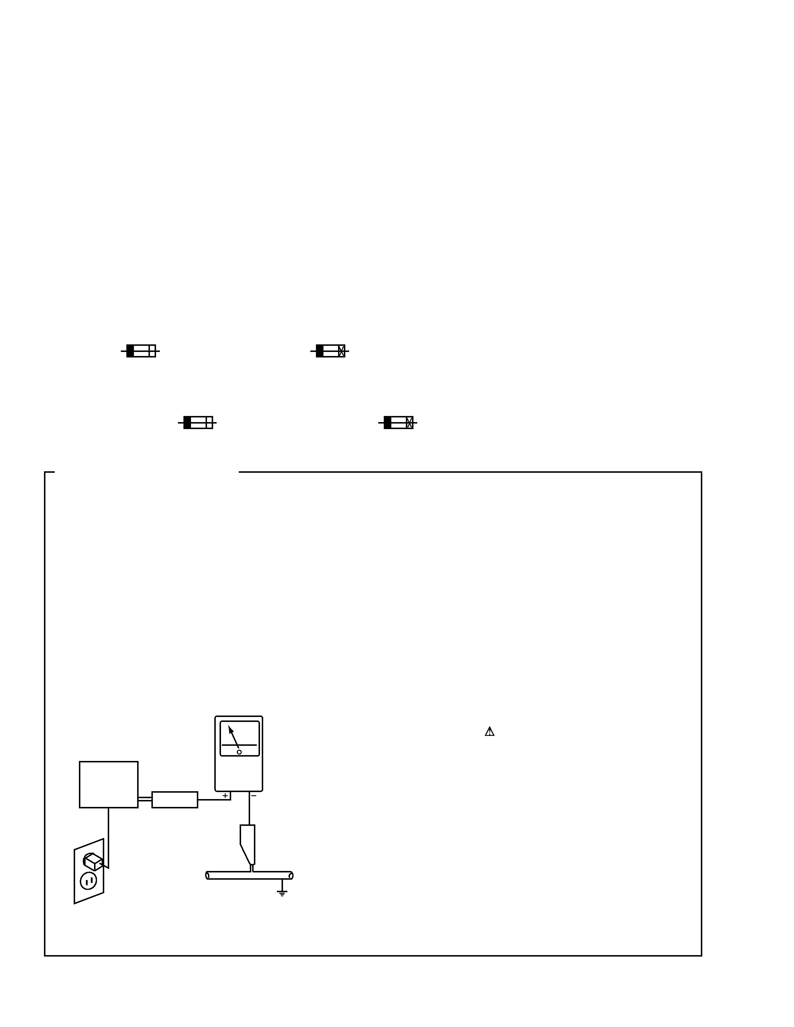
1. SAFETY PRECAUTIONS
The following check should be performed for the
continued protection of the customer and service
technician.
LEAKAGE CURRENT CHECK
Measure leakage current to a known earth ground (water
pipe, conduit, etc.) by connecting a leakage current tester
such as Simpson Model 229-2 or equivalent between the
earth ground and all exposed metal parts of the appliance
(input/output terminals, screwheads, metal overlays, control
shaft, etc.). Plug the AC line cord of the appliance directly
into a 120V AC 60Hz outlet and turn the AC power switch
on. Any current measured must not exceed 0.5mA.
(FOR USA MODEL ONLY)
Leakage
current
tester
Reading should
not be above
0.5mA
Device
under
test
Test all
exposed metal
surfaces
Also test with
plug reversed
(Using AC adapter
plug as required)
Earth
ground
AC Leakage Test
3
XC-F10
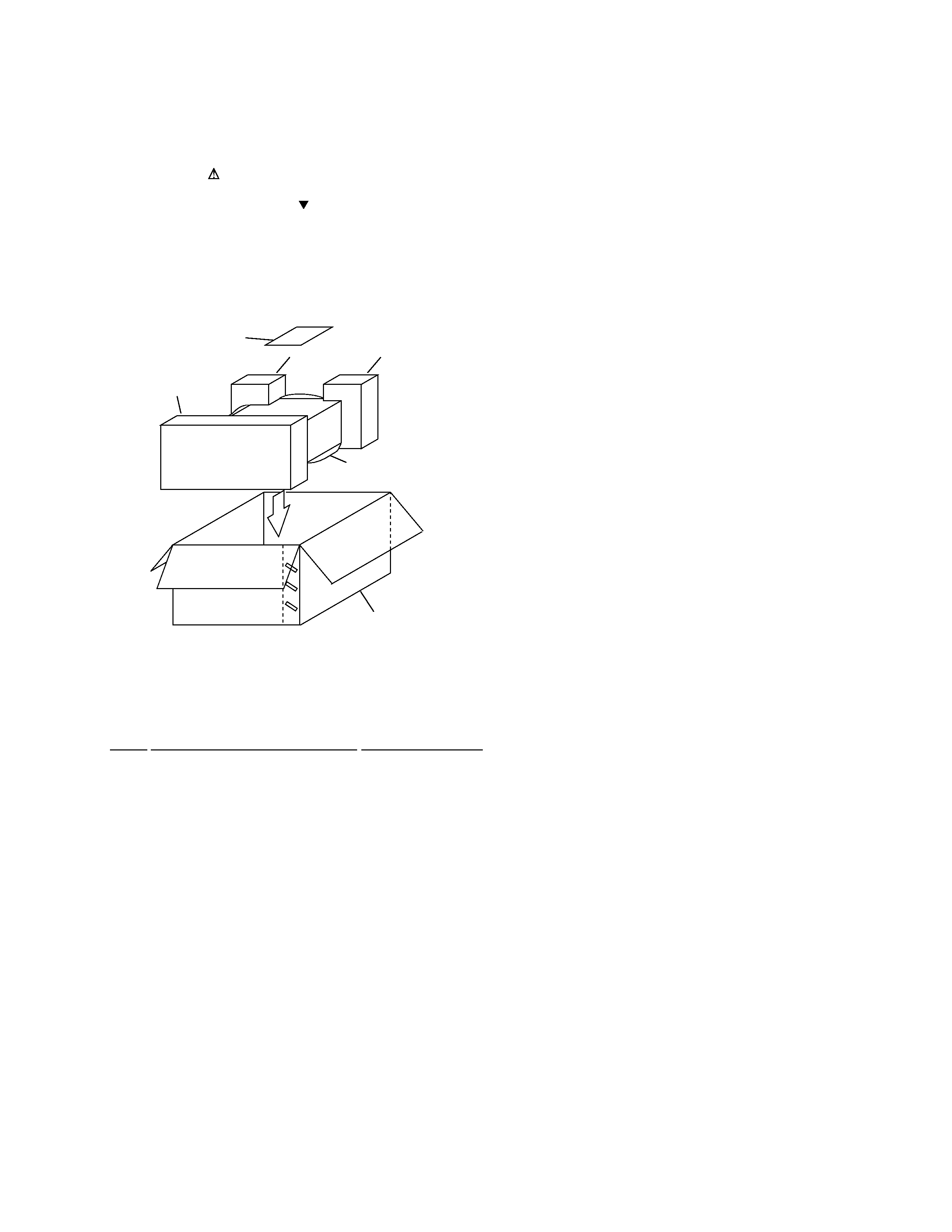
2.1 PACKING
2. EXPLODED VIEWS AND PARTS LIST
NOTES:
· Parts marked by "NSP" are generally unavailable because they are not in our Master Spare Parts List.
· The mark found on some component parts indicates the importance of the safety factor of the part.
Therefore, when replacing, be sure to use parts of identical designation.
· Screws adjacent to mark on the product are used for disassembly.
· PACKING PARTS LIST
Mark No.
Description
Part No.
1
Front Pad M
AHA7295
2
Rear Pad M
AHA7296
3
Packing Case CD/ZVY
AHD7916
4
Sheet
Z23-026
5
Stand Note
ARM7044
4
3
2 (1/2)
2 (2/2)
5
1
FRONT
4
XC-F10
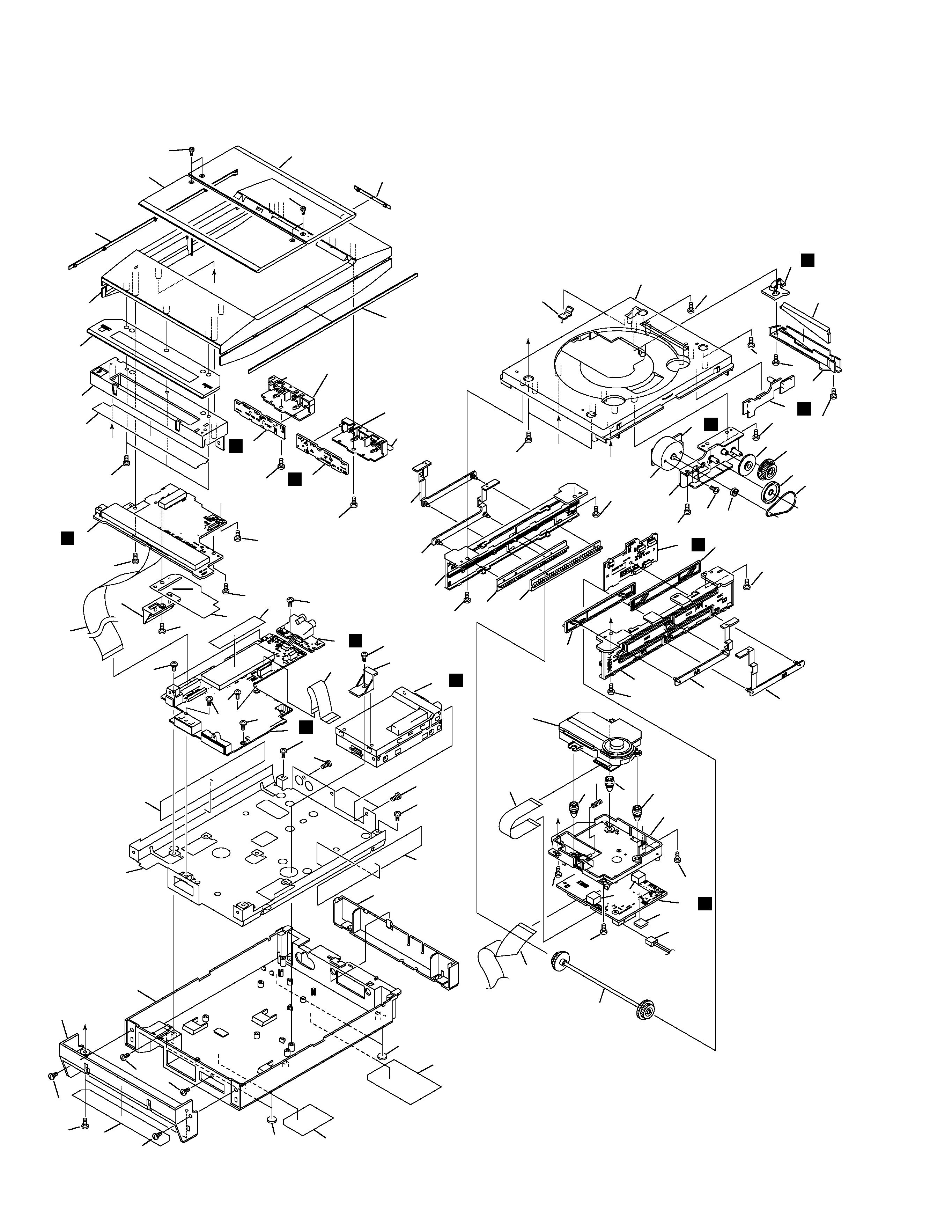
2.2 EXTERIOR
A
A
C
B
B
D
D
C
56
62
56
52
32
60
6
69
69
8
2
69
69
13
69
20
61
54
72
69
69
69
72
30
30
69
69
29
69
5
69
68
1
69
69
69
69
69
69
51
63
64
25
25
65
66
34(2/2)
47(1/4)
47(2/4)
47(4/4)
47(3/4)
34(1/2)
11
12
70
49
58
58
57
9
3
50
55
43
35
69
42
4
24
22
38
18
15
19
26
26
26
36
27
69
33
69
69
69
69
69
69
53
69
69
17
23
21
37
39
40
41
69
69
69
10
28
16
59
45
14
44
69
71 46
7
48
31(1/2)
31(2/2)
E
H
G
D
A
I
K
J
B
C
F

5
XC-F10
· EXTERIOR PARTS LIST
Mark No.
Description
Part No.
Mark No.
Description
Part No.
1
MAIN UNIT
AWU7621
2
DISP UNIT
AWU7565
3
MOTOR UNIT
AWU7566
4
CD SW UNIT
AWU7567
5
AUX UNIT
AWU7568
6
KEY L UNIT
AWU7569
7
LED UNIT
AWU7570
8
KEY R UNIT
AWU7625
9
SENS UNIT
AWU7657
NSP
10
SELF-CHACK CD ASSY
AWP7027
11
FM/AM TUNER MODULE
AXQ7228
12
13P FFC/30V (J1)
ADD7225
13
22P FFC/30V (J2)
ADD7226
14
24P FFC/30V (J5)
ADD7227
15
16P FFC/30V (J1101)
ADD7245
16
CONNECTOR ASSY (J111)
PF02PP2R05
17
Slider Motor
VXM1033
18
CD Mecha
KSM-770ABA
19
Float Spring
ABH7191
NSP
20
Bottom Chassis CD
ANA7107
21
Door Angle AL
ANG7306
22
Door Angle AR
ANG7307
23
Door Angle BL
ANG7308
24
Door Angle BR
ANG7309
25
Leg
AEB7090
26
Float Rubber
AEB7129
27
Belt
AEB7171
NSP
28
Leg
AEB7200
29
Barrier
AEC7288
30
Chassis Sheet
AEC7290
31
Mecha Holder
AMR7311
32
FL Holder
AMR7312
33
Reflector
AMR7313
34
FFC Barrier
AMR7314
35
Gear A
ANW7063
36
Gear Pulley A
ANW7066
37
Cam Base L
ANW7196
38
Cam Base R
ANW7197
39
Slide Cam A
ANW7198
40
Slide Cam B
ANW7199
41
Slide Cam C
ANW7200
42
Slide Cam D
ANW7201
43
Gear N
ANW7203
44
Gear Holder
ANW7205
45
Shaft Assy
AXG7095
46
Motor Pulley
PNW1634
47
Button CD
AAD7581
48
Door Window A
AAK7748
49
Door Window B
AAK7749
50
Sub Panel CD
AAK7771
51
Rear Cap CD
AAK7758
52
FL Window CD
AAK7773
53
Lens
AAK7806
54
FL Cover
AAK7841
55
Disc Lens
AAK7847
56
Side Line
AAP7074
57
Rear Line CD
AAP7075
58
Screw
ABA7061
59
PCB Spacer
AEB7206
60
FL Filter
AEC7273
61
Bottom Base CDMD
AMA7017
62
Top Panel CD
AMB7699
NSP
63
Name Label CD/ZU
AAL7259
64
Connector Label CD/E
ARW7093
65
65 Label
ARW7050
66
Label M
ARW7108
67
· · · · · ·
68
Screw
BBZ30P080FMC
69
Screw
BPZ30P080FZK
70
Screw
BPZ30P120FMC
71
Screw
PMZ26P040FMC
72
Screw
VBZ30P100FZK