ORDER NO.
PIONEER ELECTRONIC CORPORATION 4-1, Meguro 1-Chome, Meguro-ku, Tokyo 153-8654, Japan
PIONEER ELECTRONICS SERVICE, INC. P.O. Box 1760, Long Beach, CA 90801-1760, U.S.A.
PIONEER ELECTRONIC (EUROPE) N.V. Haven 1087, Keetberglaan 1, 9120 Melsele, Belgium
PIONEER ELECTRONICS ASIACENTRE PTE. LTD. 253 Alexandra Road, #04-01, Singapore 159936
PIONEER ELECTRONIC CORPORATION 1998
RRV2080
STEREO CD RECEIVER
XC-L5
1. SAFETY INFORMATION ...................................... 2
2. EXPLODED VIEWS AND PARTS LIST ................ 3
3. SCHEMATIC DIAGRAM ..................................... 12
4. PCB CONNECTION DIAGRAM .......................... 24
5. PCB PARTS LIST ............................................... 35
6. ADJUSTMENT .................................................... 40
CONTENTS
7. GENERAL INFORMATION ................................ 43
7.1 PARTS ......................................................... 43
7.1.1 IC ......................................................... 43
7.1.2 DISPLAY .............................................. 49
7.2 DISASSEMBLY ........................................... 51
7.3 BLOCK DIAGRAM ....................................... 53
8. PANEL FACILITIES AND SPECIFICATIONS .... 54
THIS MANUAL IS APPLICABLE TO THE FOLLOWING MODEL(S) AND TYPE(S).
Type
Model
XC-L5
KUXK/CA
AC120V
Power Requirement
Remarks
T ZZK DEC. 1998 Printed in Japan
AUX
STANDBY/ON
PHONES
7
06
¢
4
¡·+
·
1
'
VOLUME
UP
DOWN
D
XC-L5
2
1. SAFETY INFORMATION
This service manual is intended for qualified service technicians; it is not meant for the casual
do-it-yourselfer. Qualified technicians have the necessary test equipment and tools, and have been
trained to properly and safely repair complex products such as those covered by this manual.
Improperly performed repairs can adversely affect the safety and reliability of the product and may
void the warranty. If you are not qualified to perform the repair of this product properly and safely, you
should not risk trying to do so and refer the repair to a qualified service technician.
WARNING
This product contains lead in solder and certain electrical parts contain chemicals which are known to the state of California to
cause cancer, birth defects or other reproductive harm.
Health & Safety Cod e Section 25249.6 Proposition 65
NOTICE
(FOR CANADIAN MODEL ONLY)
Fuse symbols
(fast operating fuse)
and/or
(slow operating fuse) on PCB indicate that replacement
parts must be of identical designation.
REMARQUE
(POUR MODÈLE CANADIEN SEULEMENT)
Les symboles de fusible
(fusible de type rapide)
et/ou
(fusible de type lent) sur CCI indiquent que
les pièces de remplacement doivent avoir la même désignation.
ANY MEASUREMENTS NOT WITHIN THE
LIMITS OUTLINED ABOVE ARE INDICATIVE
OF A POTENTIAL SHOCK HAZARD AND
MUST BE CORRECTED BEFORE RETURN-
ING THE APPLIANCE TO THE CUSTOMER.
2. PRODUCT SAFETY NOTICE
Many electrical and mechanical parts in the appliance
have special safety related characteristics. These are
often not evident
from visual
inspection nor the
protection afforded by them necessarily can be obtained
by using replacement components rated for voltage,
wattage, etc. Replacement parts which have these
special safety characteristics are identified in this
Service Manual.
Electrical components having such features are
identified by marking with a
on the schematics and
on the parts list in this Service Manual.
The use of a substitute replacement component which
does not have the same safety characteristics as the
PIONEER recommended replacement one, shown in the
parts list in this Service Manual, may create shock, fire,
or other hazards.
Product Safety is continuously under review and new
instructions are issued from time to time. For the latest
information, always consult the current PIONEER
Service Manual. A subscription to, or
additional copies
of, PIONEER Service Manual may be obtained at a
nominal charge from PIONEER.
(FOR USA MODEL ONLY)
1. SAFETY PRECAUTIONS
The following check should be performed for the
continued protection of the customer and service
technician.
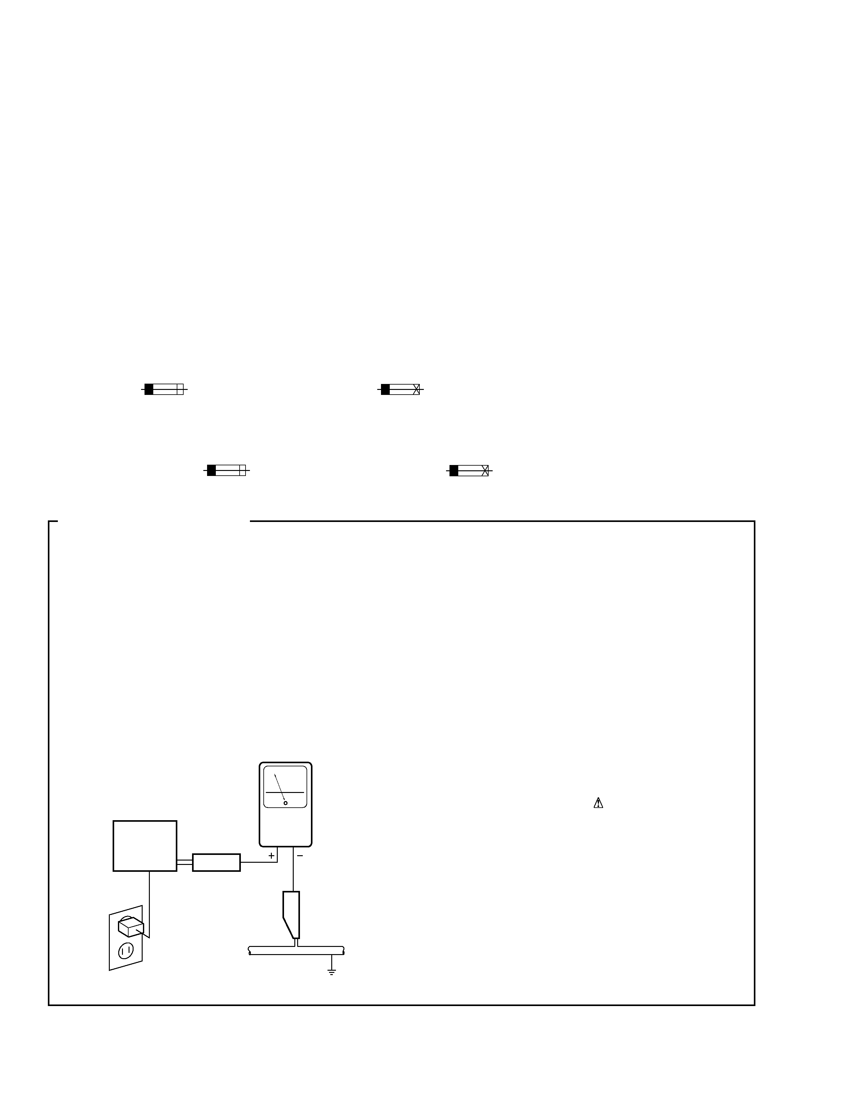
LEAKAGE CURRENT CHECK
Measure leakage current to a known earth ground
(water pipe, conduit, etc.) by connecting a leakage
current tester such as Simpson Model 229-2 or
equivalent between the earth ground and all exposed
metal parts of the appliance (input/output terminals,
screwheads, metal overlays, control shaft, etc.). Plug
the AC line cord of the appliance directly into a 120V
AC 60 Hz outlet and turn the AC power switch on. Any
current measured must not exceed 0.5 mA.
Device
under
test
Leakage
current
tester
Earth
ground
Reading should
not be above
0.5 mA
Also test with
plug reversed
(Using AC adapter
plug as required)
Test all
exposed metal
surfaces
AC Leakage Test
3
XC-L5
7
17
9
2
3
13
14
18
15(1/2)
15(2/2)
4
12
Litium Battery
1
10
11
13
5
8
19
16(2/2)
16(1/2)
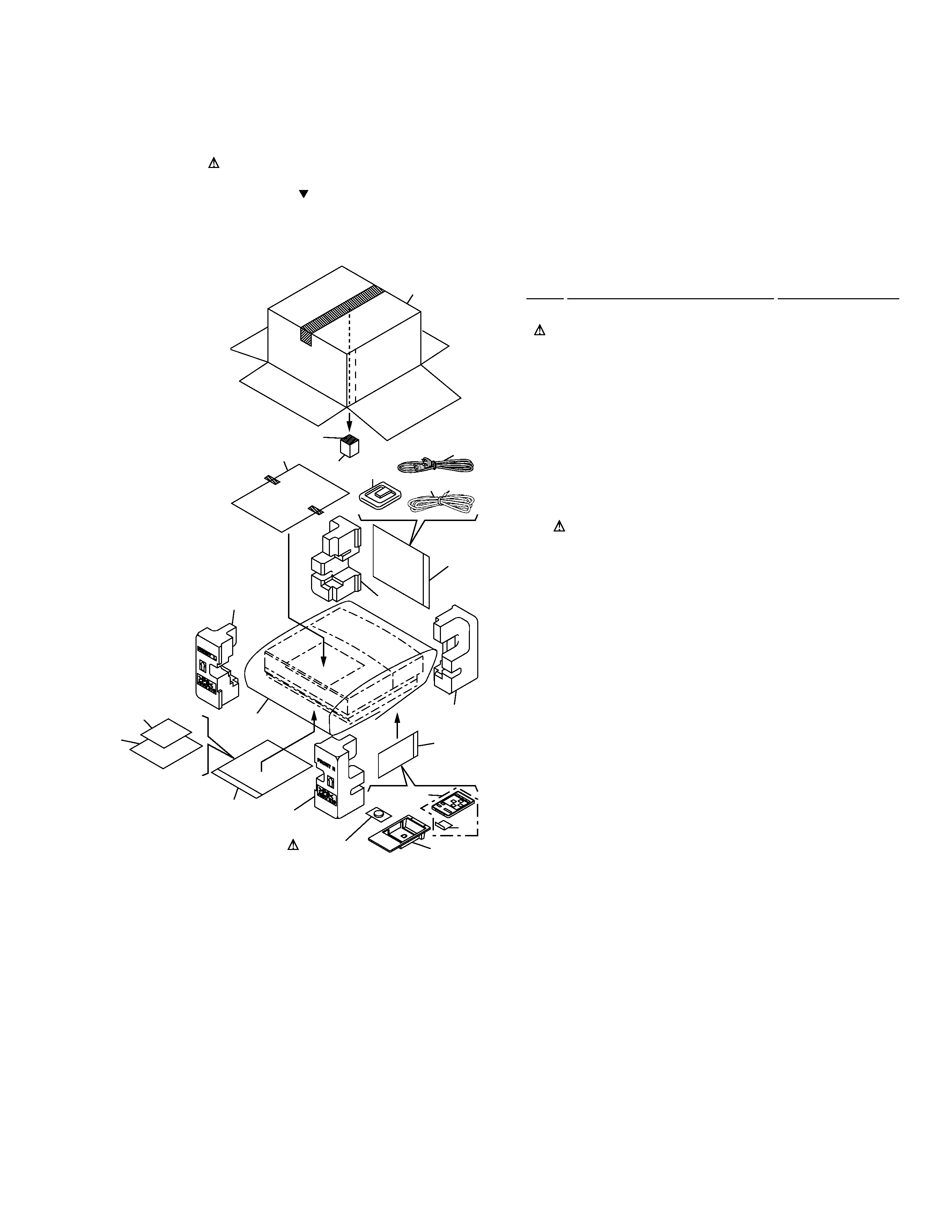
2.1 PACKING
· PACKING PARTS LIST
Mark No.
Description
Part No.
2. EXPLODED VIEWS AND PARTS LIST
NOTES:
· Parts marked by "NSP" are generally unavailable because they are not in our Master Spare Parts List.
· The mark found on some component parts indicates the importance of the safety factor of the part.
Therefore, when replacing, be sure to use parts of identical designation.
· Screws adjacent to mark on the product are used for disassembly.
1
Remote Control Unit Holder
AAH7013
2
Power Cord
ADG7022
3
FM Antenna
ADH7004
NSP
4
Vinyl Bag
AHG7031
5
Operating Instructions
ARE7205
(English/French)
6
· · · · ·
NSP
7
Demo Caution
ARR7016
NSP
8
Warranty Card
ARY7023
9
AM Loop Antenna
ATB7007
10
Remote Control Unit
AXD7170
(CU-XC005)
11
Battery Case
AZE7116
NSP
12
Lithium Battery (CR2025)
VEM1009
13
Polyethylene Bag
Z21-038
NSP
14
Technibond431
AEH7006
15
Pad F
AHA7219
16
Pad R
AHA7220
17
S Pad
AHA7230
18
Packing Case
AHD7734
19
Seat
Z23-007
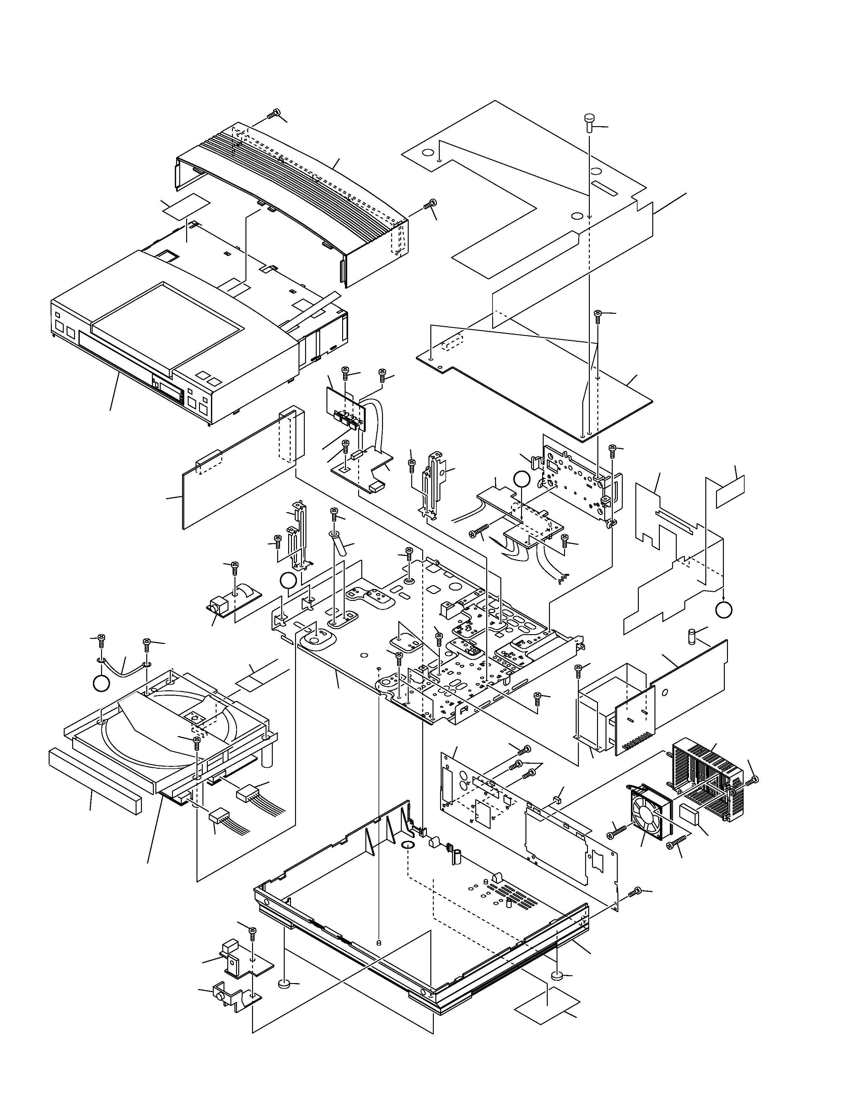
4
XC-L5
A
B
A
B
26
29
7
39
17
34
30
39
42
40
40
13
18
39
32
39
39
21
22
10
15
14
38
38
38
27
35
35
35
35
4
41
25
35
35
39
39
33
31
35
35
8
6
23
23
5
9
38
38
37
36
2
24
35
35
1
35
43
20
12
3
11
19
16
28
Refer to
"2.6 CD MECHA ASSY(1/2)".
44
Refer to
"2.3 TOP PANEL ASSY".
2.2 EXTERIOR

5
XC-L5
· EXTERIOR PARTS LIST
Mark No.
Description
Part No.
Mark No.
Description
Part No.
1
CD MAIN UNIT
AWU7113
2
CD AMP UNIT
AWU7114
3
CD TRANS UNIT
AWU7115
4
CD HP UNIT
AWU7093
5
CD REG UNIT
AWU7121
6
CD RECTIFY UNIT
AWU7128
7
CD REM UNIT
AWU7130
8
CD POWER UNIT
AWU7153
9
FM/AM TUNER MODULE
AXQ7065
10
16P F·F·C/30V
ADD7096
11
Fuse FU1 (2A)
REK1078
12
Power Transformer (T1)
ATS7219
13
DC Fan Motor
AXM7003
14
Connector 5P
AKP7040
15
Connector 6P
AKP7041
16
CD MECHA Assy
KSL-2130CCM
17
Leg
AEB7090
18
F Cushion
AEB7127
19
Center Barrier
AEC7140
20
Top Barrier
AEC7190
21
Rear Panel
ANC7801
NSP
22
Bottom Plate
ANF7010
23
Angle
ANG7189
NSP
24
Heat Sink
ANH7088
NSP
25
Cord With Plug J
DE005VF0
26
Front Leg
AEB7102
27
Cord Clamper
RNH-184
28
Tray Panel CD
AAN7193
29
Lens
AAX7639
30
Bottom Base
AMA7005
31
Bonnet
AMA7007
32
Rear Case
AMR7207
33
65 Label
ARW7050
34
Name Label
ARW7046
35
Screw
BBZ30P060FMC
36
Screw
BBZ30P140FMC
37
Screw
BBZ40P060FMC
38
Screw
BPZ30P060FZK
39
Screw
BPZ30P100FZK
40
Screw
BPZ30P300FMC
41
Screw
PDZ30P060FMC
42
Cushion Rubber
AEB7068
43
Rivet
VEC1178
NSP
44
Fuse Caution A
AAX7724