ORDER NO.
PIONEER CORPORATION 4-1, Meguro 1-chome, Meguro-ku, Tokyo 153-8654, Japan
PIONEER ELECTRONICS SERVICE, INC. P.O. Box 1760, Long Beach, CA 90801-1760, U.S.A.
PIONEER EUROPE NV Haven 1087, Keetberglaan 1, 9120 Melsele, Belgium
PIONEER ELECTRONICS ASIACENTRE PTE. LTD. 253 Allexandra Road, #04-01, Singapore 159936
PIONEER ELECTRONIC CORPORATION 2000
c
RRV2326
XC-IS21V
1. SAFETY INFORMATION ....................................... 2
2. EXPLODED VIEWS AND PARTS LIST ................. 3
3. BLOCK DIAGRAM AND SCHEMATIC DIAGRAM 16
4. PCB CONNECTION DIAGRAM ........................... 37
5. PCB PARTS LIST ................................................ 48
6. ADJUSTMENT ..................................................... 53
7. GENERAL INFORMATION .................................. 59
CONTENTS
7.1 DIAGNOSIS ....................................................... 59
7.1.1 SEQUNCE AFTER THE POWER ON ... 59
7.1.2 SINGLE OPERATION METHOD .......... 60
7.1.3 DISASSEMBLY .................................... 62
7.1.4 PCB LOCATION ................................... 66
7.1 PARTS ............................................................. 67
7.2.1 IC .......................................................... 67
8. PANEL FACILITIES AND SPECIFICATIONS ....... 78
T ZZY JULY 2000 Printed in Japan
THIS MANUAL IS APPLICABLE TO THE FOLLOWING MODEL(S) AND TYPE(S).
STEREO CD/VCD TUNER DECK
Remarks
Type
Model
XC-IS21V
Power Requirement
ZBDXJ
O
DC power supply from other system
ZLXJ/NC
O
DC power supply from other system
This product is a system(s) component.
This product does not function properly when independent; to avoid malfunctions, be sure
to connect it to the prescribed system component(s), otherwise damage may result.
STEREO CD/VCD TUNER DECK XC-IS21V
STEREO CD/VCD TUNER DECK
XC-IS21V
RRV2326
This service manual
STEREO POWER AMPLIFIER
M-IS21
RRV2129
SPEAKER SYSTEM
S-IS21V
RRV2335
System
XC-IS21V
Component
Service Manual
Remarks
XC-IS21V
2
1. SAFETY INFORMATION
This service manual is intended for qualified service technicians; it is not meant for the casual
do-it-yourselfer. Qualified technicians have the necessary test equipment and tools, and have been
trained to properly and safely repair complex products such as those covered by this manual.
Improperly performed repairs can adversely affect the safety and reliability of the product and may
void the warranty. If you are not qualified to perform the repair of this product properly and safely, you
should not risk trying to do so and refer the repair to a qualified service technician.
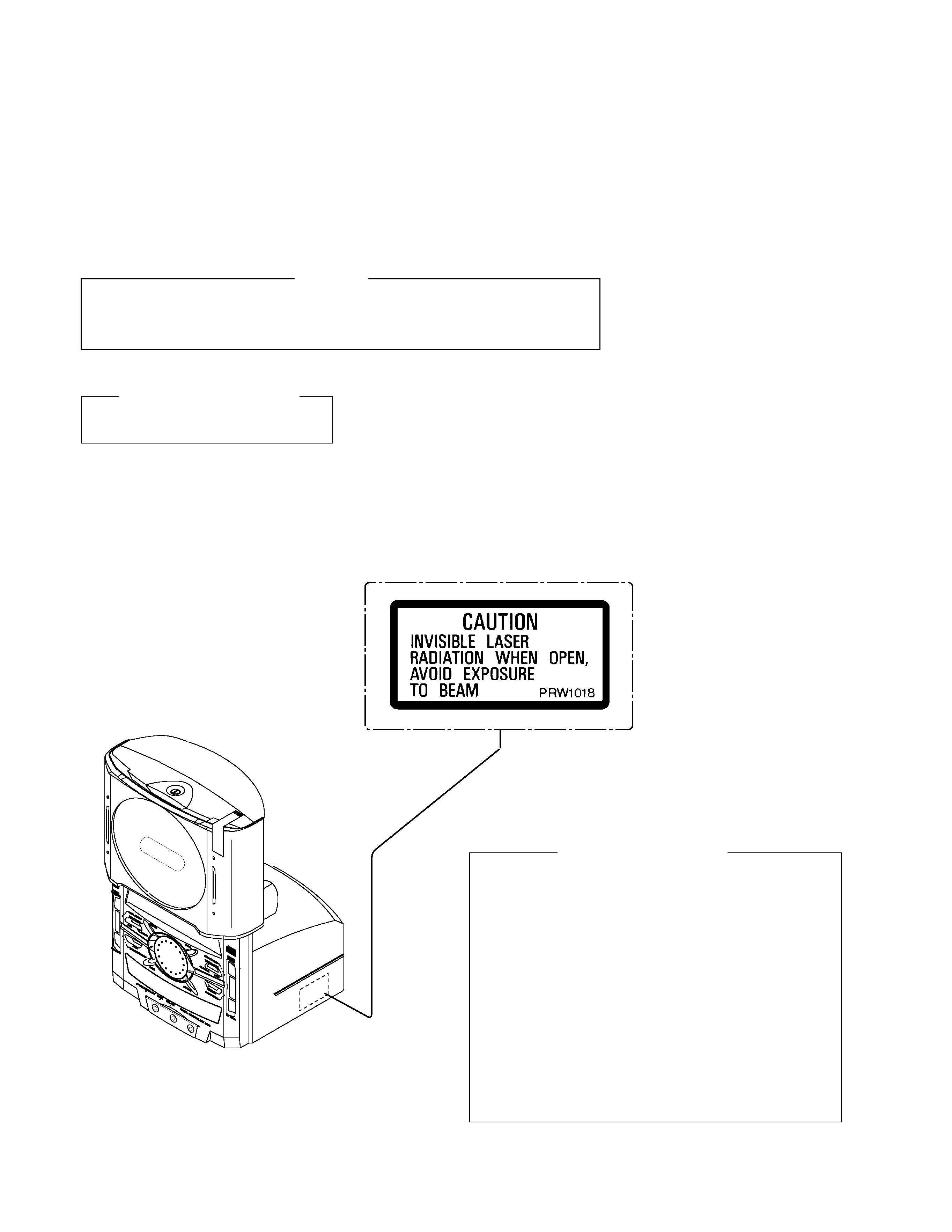
LASER DIODE CHARACTERISTICS
MAXIMUM OUTPUT POWER: 5 mW
WAVELENGTH: 708- 785 nm
LABEL CHECK
1. Laser Interlock Mechanism
The loading position detect switch (in CD mechanism
assembly) is set to "CLMP ON(CD CLOSE)" (ON:low
level,OFF:high level) position, the system control
IC(IC5501) get the "CLMP" signal, and hand the laser
"LDON" signal to IC1101.
Then a laser diode can be lighted except when the level of
signal CLMP is low.
The interlock also does not function in the test mode
.
Laser diode oscillation will continue, if pin 9 of TA2150FN
(IC1101) on the SELF-CHUCK VCD ASSY is connected to
GND, or pin 10 is connected to low level (ON), or else the
terminals of Q1101 are shorted to each other (fault
condition).
2. When the cover is opened, close viewing of the objective
lens with the naked eye will cause exposure to a Class 1
laser beam.
: Refer to page 56.
Additional Laser Caution
(Right side view)
WARNING
THE AEL(ACCESSIBLE EMISSION LEVEL) OF THE LASER POWER OUTPUT IS LESS THAN CLASS 1
BUT THE LASER COMPONENT IS CAPABLE OF EMITTING RADIATION EXCEEDING THE LIMIT FOR
CLASS1.
A SPECIALLY INSTRUCTED PERSON SHOULD DO SERVICING OPERATION OF THE APPARATUS.
3
XC-IS21V
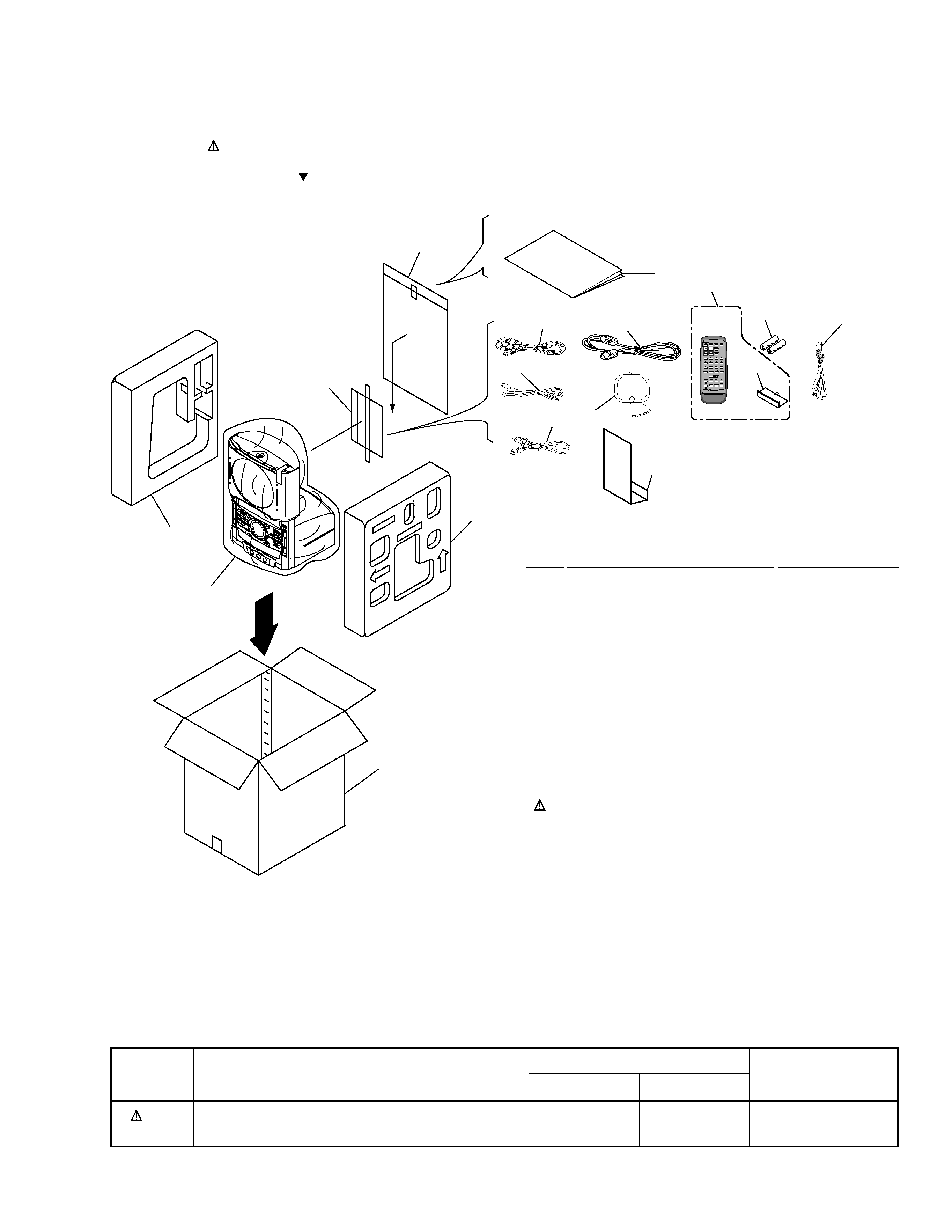
2.1 PACKING
2. EXPLODED VIEWS AND PARTS LIST
NOTES:
· Parts marked by "NSP" are generally unavailable because they are not in our Master Spare Parts List.
· The mark found on some component parts indicates the importance of the safety factor of the part.
Therefore, when replacing, be sure to use parts of identical designation.
· Screws adjacent to mark on the product are used for disassembly.
(2) CONTRAST TABLE
XC-IS21V/ZBDXJ and ZLXJ/NC are constructed the same except for the following:
Mark
ZBDXJ type
ZLXJ/NC type
12
Power Cord
ADG1158
ADG1154
18
Packing Case
AHD7909
AHD7910
Part No.
Remarks
Symbol and Description
No.
9
10
14
13
13
2
8
11
19
1
16
15
12
4
7
17
18
(1) PACKING PARTS LIST
Mark No.
Description
Part No.
1
System Cable
ADE7039
2
FM Antenna
ADH7004
3
· · · · ·
4
Operating Instructions
ARE7268
(English/Chinese)
5
· · · · ·
6
· · · · ·
7
Protection Board
AHB7039
8
AM Loop Antenna
ATB7007
9
Remote Control Unit
AXD7281
10
RCA Pin- plug Stereo Cable
VDE1052
(L= 1.5m)
NSP
11
Dry Cell Batteries(AA/R6)
VEM-013
12
Power Cord
See Contrast table (2)
NSP
13
Polyethylene Bag
Z21-038
(0.03 x 230 x 340)
14
Video Cable
VDE1034
15
Side Pad ML
AHA7240
16
Side Pad MR
AHA7241
17
Packing Sheet
AHG7053
18
Packing Case
See Contrast table (2)
19
Battery Cover
AZA7400
4
XC-IS21V
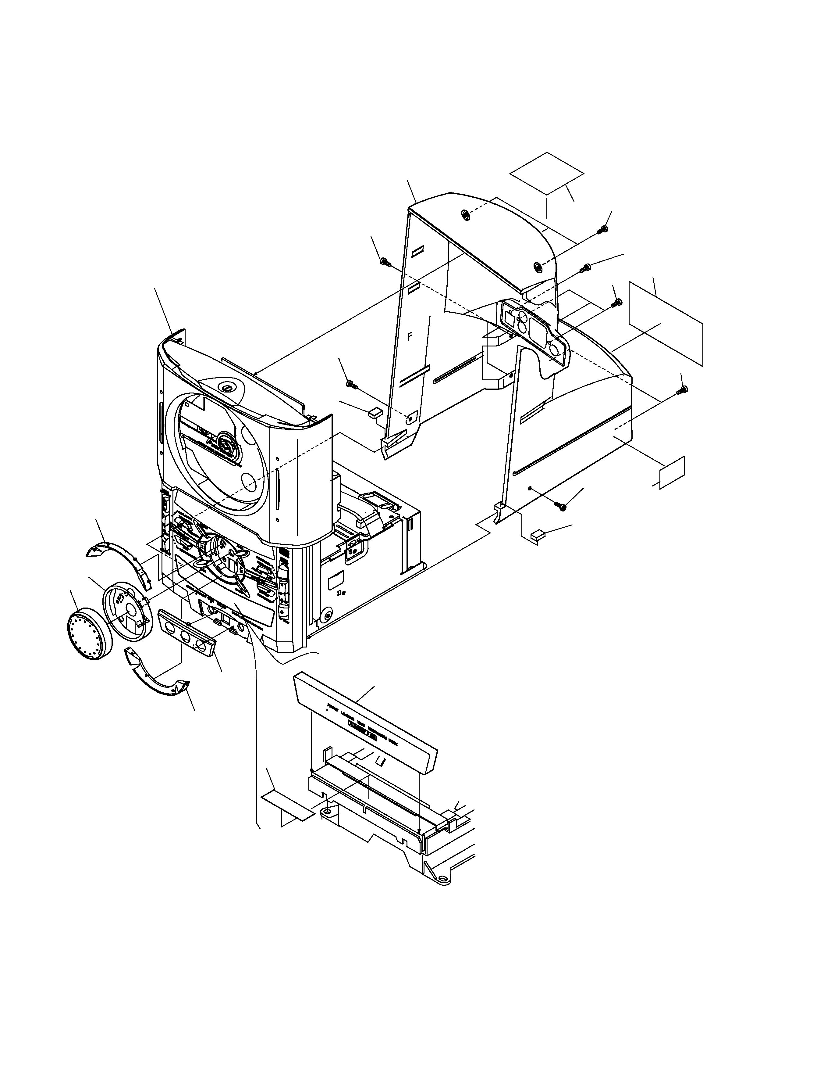
2.2 EXTERIOR (1/2)
10
12
14
9
9
5
6
8
7
4
8
3
2
10
1
10
9
2
13
11
Refer to "2.4 FRONT PANAEL ASSY (1/2)
and 2.5 FRONT PANEL ASSY (2/2)"
5
XC-IS21V
1
Rear Cover
AMC7043
2
Cussion Rubber
AEB7212
3
Jack Door
AAN7188
4
Jog Lens
AAK7651
5
Jog Knob
AAA7005
6
Tray Cap
AAK7622
NSP
7
Tray Seal
RRW1162
8
Jog Escutcheon
AAK7620
9
Screw
BBZ30P080FMC
10
Screw
VPZ30P100FMC
11
Screw
BMZ30P060FZK
NSP
12
Name Label
See Contrast table (2)
13
Caution Label
PRW1018
14
Label M
See Contrast table (2)
(1) EXTERIOR (1/2) PARTS LIST
Mark No.
Description
Parts No.
(2) CONTRAST TABLE
XC-IS21V/ZBDXJ and ZLXJ/NC are constructed the same except for the following:
Mark
ZBDXJ type
ZLXJ/NC type
NSP
12
Name Label
AAL7256
AAL7257
14
Label M
ARW7065
Not used
Part No.
Remarks
Symbol and Description
No.