
1
TZ-S700
Service
Manual
ORDER NO.
PET98010
65S
This service manual is intended for qualified service technicians; it
is not meant for the casual do-it- your selfer. Qualified technicians
have the necessary test equipment and tools, and have been trained
to properly and safely repair complex products such as those cov-
ered by this manual.
Improperly performed repairs can adversely affect the safety and
reliability of the product and may void the warranty. If you are not
qualified to perform the repair of this product properly and safely,
you should not risk trying to do so and refer the repair to a quali-
fied service technician.
SPEAKER SYSTEM
TZ-S700
PIONEER ELECTRONIC CORPORATION 4-1, Meguro 1-Chome, Meguro-ku, Tokyo 153-8654, Japan
PIONEER ELECTRONICS SERVICE, INC. P.O. Box 1760, Long Beach, CA 90801-1760, U.S.A.
PIONEER ELECTRONIC (EUROPE) N.V. Haven 1087, Keetberglaan 1 B-9120 Melsele, Belgium
PIONEER ELECTRONICS ASIACENTRE PTE. LTD. 501 Orchard Road, #10-00, Wheelock Place, Singapore 238880
©PIONEER ELECTRONIC CORPORATION 1998
1999 Printed in U.S.A.

2
TZ-S700
1. GRILLE
1.1 REMOVAL
1. Gently prise the grille away from the cabinet by pulling
around the perimeter.
2. To help start the process, insert a slim object, such as a
pencil, through the wall mounting holes visible on the rear of
the cabinet.
1.2 REFITTING
1. Re-locate the grille edges into the groove in the front of the
cabinet.
2. Push gently around the perimeter of the grille until it is
evenly seated all around.
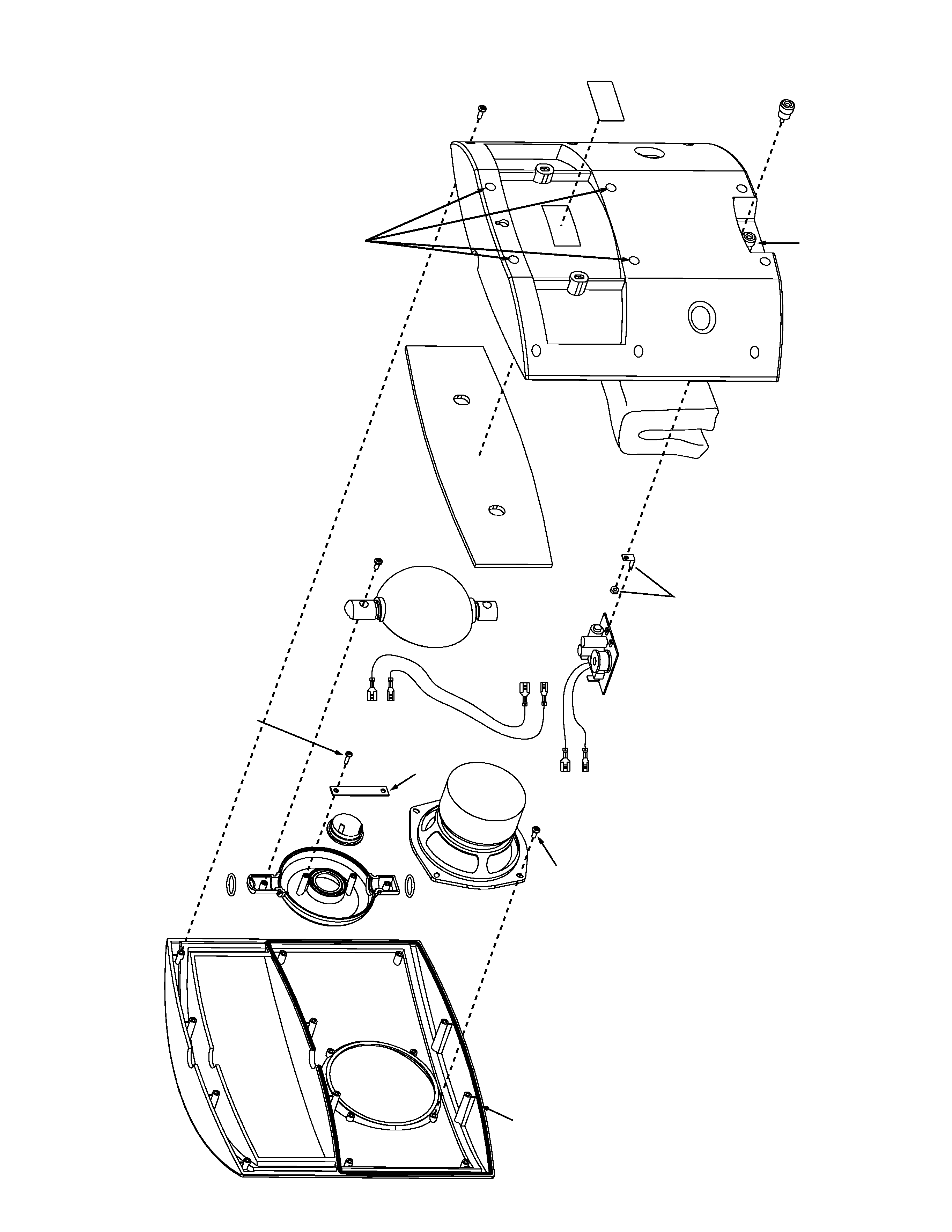
2. MAIN CABINET
2.1 DISASSEMBLY
1. Lay the cabinet down on it's front surface.
2. Remove the 12 screws from the rear of the cabinet.
3. Turn the cabinet over onto it's back surface.
4. Gently pull apart the front and rear sections of the cabinet.
5. Disconnect the blue and white wires from the LF unit.
6. Fully separate the cabinet sections.
2.2 ASSEMBLY
1. Make sure the acoustic absorbent does not block the two
ports.
2. Make sure that the Seal Strip is fully located in the peripheral
groove.
3. Lay the rear section down on it's back surface.
4. Reconnect the blue and white wires to the LF unit.
5. Locate the bull assembly into the rear section, with the
tweeter facing upward.
6. Locate the front section over the rear section, and snap into
position.
7. Replace the 12 screws and tighten to a torque of 4-6 lb-in for
the 4 "signed" screws, and 8-10 lb-in for the rest.
3. WOOFER
3.1 REMOVAL
1. Disassemble the cabinet as described in section 2.1.
2. Remove the 4 screws holding the woofer.
3. Remove the woofer.
3.2 REFITTING
1. Re-position the woofer, aligning the chassis holes with the
screw bosses, with the terminal panel position to the side
edge.
2. Replace the 4 screws and tighten to a torque of 4.0 lb-in.
3. Reassemble the cabinet as described in section 2.2.
4. BALL ASSEMBLY
4.1 REMOVAL
1. Disassemble the cabinet as described in section 2.1.
2. Disconnect the red and red/black wires from the crossover.
3. Lift the ball assembly away from the cabinet.
4.2 REFITTING
1. With the rear cabinet on it's back surface, locate the ball into
the rear cabinet, with the tweeter facing upward.
2. Reconnect the red/black wires to the crossover.
3. Complete the cabinet re-assembly as described in section
2.2.
5. TWEETER
5.1 REMOVAL
1. Disassemble the cabinet as described in section 2.1.
2. Remove the ball assembly as described in section 4.
3. Carefully remove the two O-ring seals.
4. Face the ball downwards, and remove the 2 screws.
5. Pull apart the two halves of the ball.
6. Disconnect the wire assembly from the tweeter.
7. Remove the 2 screws (#6
×1/2") and the clamp bar.
8. Remove the tweeter.
5.2 REFITTING
1. Place front section of ball face down.
2. Position tweeter over centre hole location.
3. Orient tweeter so that the connectors are positioned evenly
between the screw basses.
4. Replace the clamp bar over the tweeter, making sure that it
dose not contact the connectors.
5. Replace the 2 screws(#6
×1/2") and tighten.
6. Reconnect the wire assembly.
7. Lay the wire in the rear half of the ball such that it snakes
around the screw boss and exits through the slot.
8. Carefully bring the two halves together making sure not to
trap the wire.
9. Replace the two screws(#8
×3/8") and tighten.
10. Replace the two O-ring seals and if necessary re-lubricate
with Vaseline.
11. Re-hit the ball assembly as described in section 4.2
6. CROSSOVER
6.1 REMOVAL
1. Disassemble the cabinet as described in section 2.1.
2. Disconnect the red and red/black wires from the crossover.
3. Peal away the hot melt from the edge of the crossover.
4. Pull the crossover upwards, to disconnect from the binding
posts.
6.2 REFITTING
1. Push the crossover downwards in the slot until the connec-
tors engage with the tags on the binding posts.
2. Secure edge of crossover to the slots with hot melt.
3. Reconnect the red and red/black wires.
4. Re-assemble as described in section 2.2.
3
TZ-S700
RED
.187F
HF
+
RED/BLA
CK
.110F
HF
-
RED
.187F
HF
+
(XO
VER)
RED/BLA
CK
.110F
HF
-
(XO
VER)
BLUE
.250F
B125
LF
+
WHITE
.110F
B125
LF
-
SEAL
STRIP
B125
LF
TRANS
SCREW
#8
×3/8"
4
PCS
.
P/N:
261478
O-RING
O-RING
BALL,
FR
ONT
HF
TRANS
SCREW
#6
×1/2"
2
PCS
.
P/N:
227676
CLAMP
BAR
BALL,
REAR
SCREW
#8
×3/8"
2
PCS
.
P/N:
261478
CR
OSSO
VER
NETW
ORK
ASSY
FO
AM
P
AD
SET
(FEL
T)
A
COUSTIC
ABSORBENT
(POL
YESTER
FIBER)
CABINET
,REAR
P/N:
261032
BINDING
POST
RED
P/N:
260262
BINDING
POST
BLA
CK
P/N:
260277
T
AB
&
NUT
(INCLUDING
BINDING
POST)
LABEL
BA
CK
SCREW
#8
×1/2"
12
PCS
.
P/N:
261621
BAFFLE
w/GRILLE
T
orque:
4-6
lb-in.
4
TZ-S700
Instruction Manual
260891
B125 LF Transducer
260782
High Freq. Transducer
260831
Clamp Bar
260975
Ball, Front
260980
Ball, Rear
260995
O-Ring
261007
HF Wire Assembly
262624
Baffle with Grille
263627
NSP Cabinet, Rear
261032
Seal Strip (Neoprene 3mm Dia.)
261047
NSP Foam Pad Set (Felt)
261052
NSP Acoustic Absorbent (Poly Fiber)
261067
For Packing
Crossover Network Assy
261072
Binding Post, Red
260262
Binding Post, Black
260277
Screw (SPA0006P01/2FZB)
227676
Screw (SPV0008P03/8FZB)
261478
Screw (SPV0008P01/2FZW)
261621
Mark
No. Description
Parts No.
Mark
No. Description
Parts No.
Mark
No. Description
Parts No.
Packing Case
260866
Foam Pad
260871
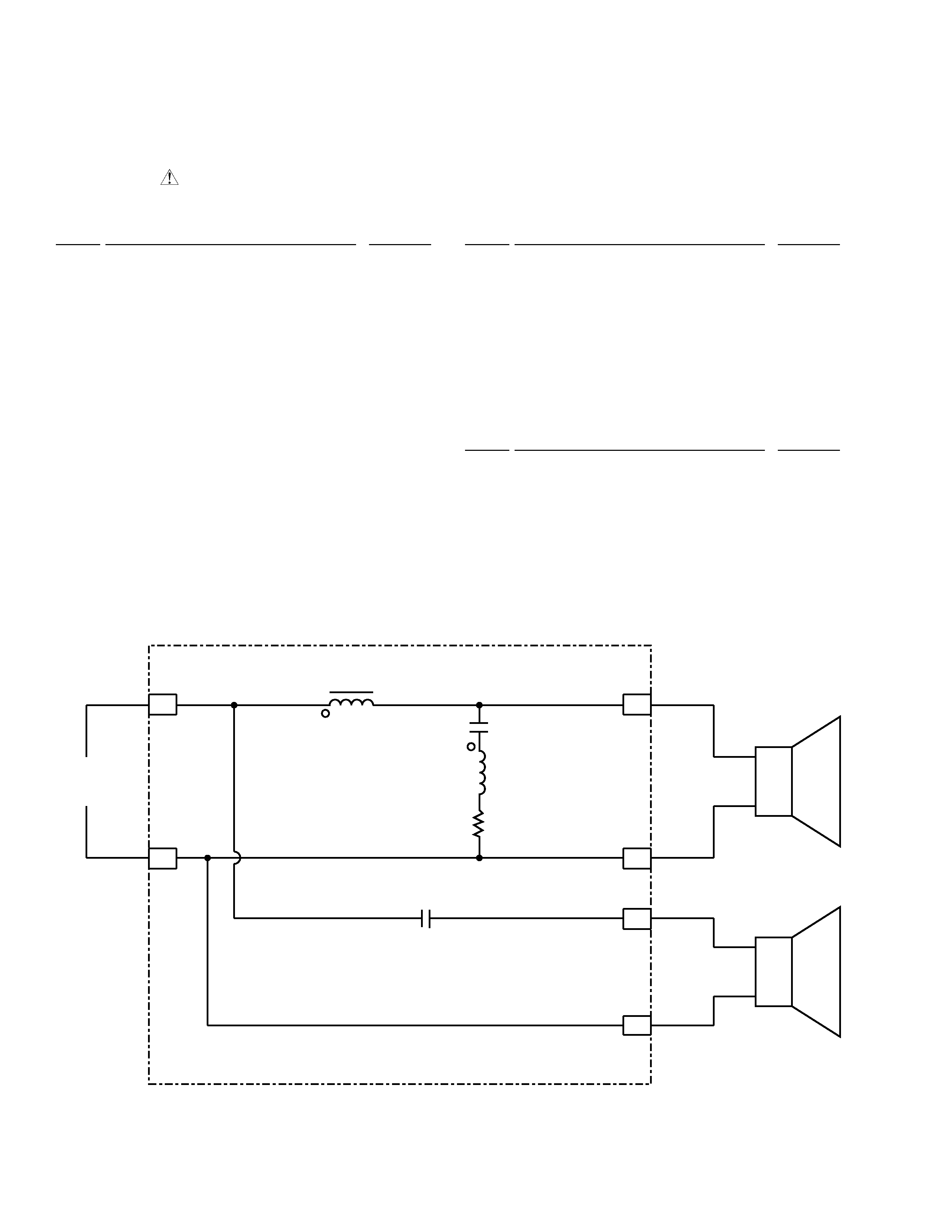
SCHEMATIC DIAGRAM
PARTS LIST
NOTES: · Parts marked by "NSP" are generally unavailable because they are not in our Master Spare Parts List.
· The "
" mark found on some component parts indicates the importance of the safety factor of the part.
Therefore, when replacing, be sure to use parts of identical designation.
ª
·
·
ª
Tweeter
INPUT
3.3
µF / 50V
0.45 mH
20
µF / 50V
0.08 mH
3.9
/7W
187
110
205
110
205
205
BLUE
RED
BLACK
WHITE
Woofer
B-POST
RED
B-POST
BLACK
CROSSOVER NETWORK ASSEMBLY (261072)