ORDER NO.
PIONEER CORPORATION 4-1, Meguro 1-chome, Meguro-ku, Tokyo 153-8654, Japan
PIONEER ELECTRONICS (USA) INC. P.O. Box 1760, Long Beach, CA 90801-1760, U.S.A.
PIONEER EUROPE NV Haven 1087, Keetberglaan 1, 9120 Melsele, Belgium
PIONEER ELECTRONICS ASIACENTRE PTE. LTD. 253 Alexandra Road, #04-01, Singapore 159936
PIONEER CORPORATION 2002
ARP3129
CANAL PLUS TUNER
TS7
T ZZV AUG. 2002 Printed in Japan
TS7
OK
CB
/ I
BCT-1710
BCT-1720
BCT-1730
Type
Model
Power Requirement
Remarks
TS7
BCT-1710 BCT-1720 BCT-1730
NYXK/FR
AC230V
NYXK/SP
AC230V
NYXK/IT
AC230V
NYWXK/PL
AC230V
THIS MANUAL IS APPLICABLE TO THE FOLLOWING MODEL(S) AND TYPE(S).
For details, refer to "Important symbols for good services" on the next page.
2
1
23
4
12
3
4
C
D
F
A
B
E
TS7, BCT-1710, BCT-1720, BCT-1730
SAFETY INFORMATION
This service manual is intended for qualified service technicians; it is not meant for the casual
do-it-yourselfer. Qualified technicians have the necessary test equipment and tools, and have been
trained to properly and safely repair complex products such as those covered by this manual.
Improperly performed repairs can adversely affect the safety and reliability of the product and may
void the warranty. If you are not qualified to perform the repair of this product properly and safely, you
should not risk trying to do so and refer the repair to a qualified service technician.
WARNING
This product contains lead in solder and certain electrical parts contain chemicals which are known to the state of California to
cause cancer, birth defects or other reproductive harm.
Health & Safety Code Section 25249.6 Proposition 65
NOTICE
(FOR CANADIAN MODEL ONLY)
Fuse symbols
(fast operating fuse)
and/or
(slow operating fuse) on PCB indicate that replacement
parts must be of identical designation.
REMARQUE
(POUR MODÈLE CANADIEN SEULEMENT)
Les symboles de fusible
(fusible de type rapide)
et/ou
(fusible de type lent) sur CCI indiquent que
les pièces de remplacement doivent avoir la même désignation.
ANY MEASUREMENTS NOT WITHIN THE
LIMITS OUTLINED ABOVE ARE INDICATIVE
OF A POTENTIAL SHOCK HAZARD AND
MUST BE CORRECTED BEFORE RETURN-
ING THE APPLIANCE TO THE CUSTOMER.
2. PRODUCT SAFETY NOTICE
Many electrical and mechanical parts in the appliance
have special safety related characteristics. These are
often not evident
from visual
inspection nor the
protection afforded by them necessarily can be obtained
by using replacement components rated for voltage,
wattage, etc. Replacement parts which have these
special safety characteristics are identified in this
Service Manual.
Electrical components having such features are
identified by marking with a
on the schematics and
on the parts list in this Service Manual.
The use of a substitute replacement component which
does not have the same safety characteristics as the
PIONEER recommended replacement one, shown in the
parts list in this Service Manual, may create shock, fire,
or other hazards.
Product Safety is continuously under review and new
instructions are issued from time to time. For the latest
information, always consult the current PIONEER
Service Manual. A subscription to, or
additional copies
of, PIONEER Service Manual may be obtained at a
nominal charge from PIONEER.
(FOR USA MODEL ONLY)
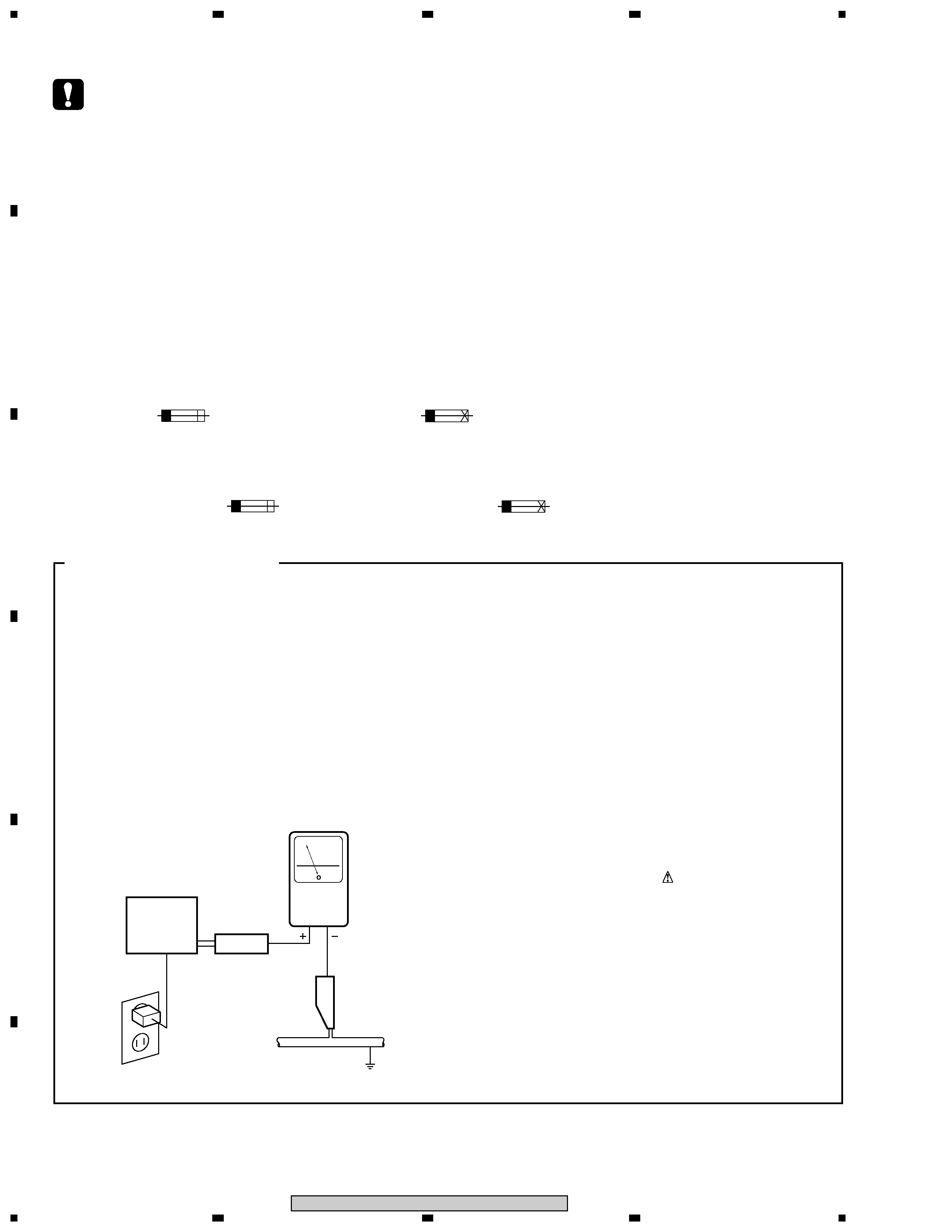
1. SAFETY PRECAUTIONS
The following check should be performed for the
continued protection of the customer and service
technician.
LEAKAGE CURRENT CHECK
Measure leakage current to a known earth ground
(water pipe, conduit, etc.) by connecting a leakage
current tester such as Simpson Model 229-2 or
equivalent between the earth ground and all exposed
metal parts of the appliance (input/output terminals,
screwheads, metal overlays, control shaft, etc.). Plug
the AC line cord of the appliance directly into a 120V
AC 60 Hz outlet and turn the AC power switch on. Any
current measured must not exceed 0.5 mA.
Device
under
test
Leakage
current
tester
Earth
ground
Reading should
not be above
0.5 mA
Also test with
plug reversed
(Using AC adapter
plug as required)
Test all
exposed metal
surfaces
AC Leakage Test
3
1
23
4
1
2
3
4
C
D
F
A
B
E
TS7, BCT-1710, BCT-1720, BCT-1730
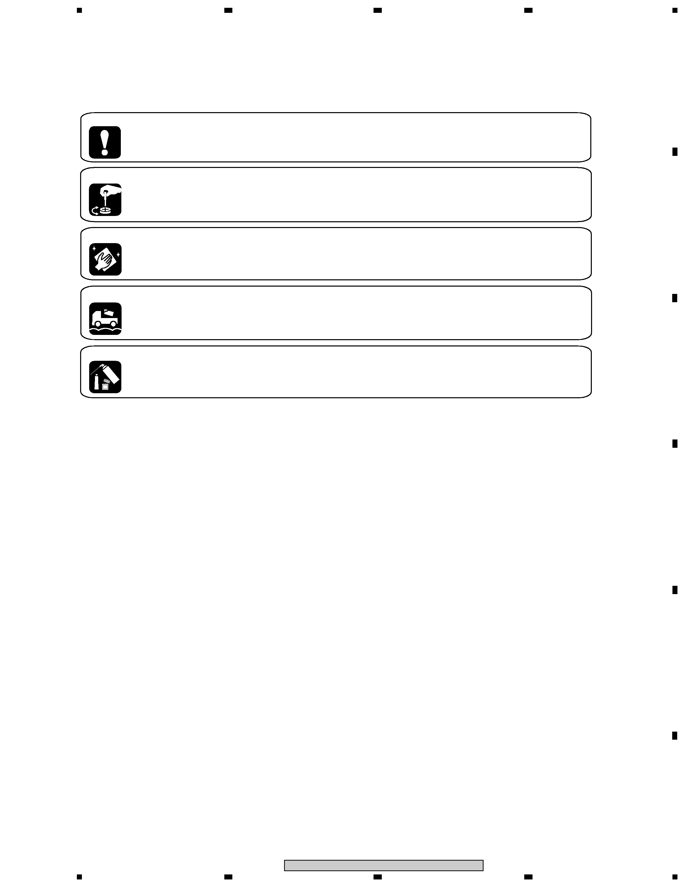
[ Important symbols for good services ]
In this manual, the symbols shown-below indicate that adjustments, settings or cleaning should be made securely.
When you find the procedures bearing any of the symbols, be sure to fulfill them:
2. Adjustments
To keep the original performances of the product, optimum adjustments or specification confirmation is indispensable.
In accordance with the procedures or instructions described in this manual, adjustments should be performed.
3. Cleaning
For optical pickups, tape-deck heads, lenses and mirrors used in projection monitors, and other parts requiring cleaning,
proper cleaning should be performed to restore their performances.
5. Lubricants, glues, and replacement parts
Appropriately applying grease or glue can maintain the product performances. But improper lubrication or applying
glue may lead to failures or troubles in the product. By following the instructions in this manual, be sure to apply the
prescribed grease or glue to proper portions by the appropriate amount.For replacement parts or tools, the prescribed
ones should be used.
4. Shipping mode and shipping screws
To protect the product from damages or failures that may be caused during transit, the shipping mode should be set or
the shipping screws should be installed before shipping out in accordance with this manual, if necessary.
1. Product safety
You should conform to the regulations governing the product (safety, radio and noise, and other regulations), and
should keep the safety during servicing by following the safety instructions described in this manual.

4
1
23
4
12
3
4
C
D
F
A
B
E
TS7, BCT-1710, BCT-1720, BCT-1730
CONTENTS
SAFETY INFORMATION ...................................................................................................................................... 2
1. SPECIFICATIONS ............................................................................................................................................ 5
2. EXPLODED VIEWS AND PARTS LIST .......................................................................................................... 6
2.1 PACKING .................................................................................................................................................... 6
2.2 EXTERIOR .................................................................................................................................................8
3. SCHEMATIC DIAGRAM ................................................................................................................................ 10
3.1 BLOCKDIAGRAM .................................................................................................................................... 10
3.2 OVERALL WIRING DIAGRAM ................................................................................................................ 12
3.3 MAIN ASSY (1/8) ..................................................................................................................................... 14
3.4 MAIN ASSY (2/8) ..................................................................................................................................... 16
3.5 MAIN ASSY (3/8) ..................................................................................................................................... 18
3.6 MAIN ASSY(4/8) ...................................................................................................................................... 20
3.7 MAIN ASSY(5/8) ...................................................................................................................................... 22
3.8 MAIN ASSY(6/8) ...................................................................................................................................... 24
3.9 MAIN ASSY(7/8) ...................................................................................................................................... 26
3.10 MAIN ASSY(8/8) .................................................................................................................................... 28
3.11 FRONT ASSY ........................................................................................................................................ 30
3.12 CARD ASSY .......................................................................................................................................... 31
3.13 MODEM ASSY ...................................................................................................................................... 32
3.14 POWER ASSY ...................................................................................................................................... 34
4. PCB CONNECTION DIAGRAM ..................................................................................................................... 36
4.1 FRONT ASSY .......................................................................................................................................... 36
4.2 CARD AND MODEM ASSYS .................................................................................................................. 37
4.3 MAIN ASSY ............................................................................................................................................. 38
5. PCB PARTS LIST .......................................................................................................................................... 42
6. ADJUSTMENT ............................................................................................................................................... 45
7. GENERAL INFORMATION ............................................................................................................................ 46
7.1 DIAGNOSIS ............................................................................................................................................. 46
7.1.1 CHECK MODE ................................................................................................................................. 46
7.1.2 TROUBLESHOOTING ..................................................................................................................... 53
7.2 IC ............................................................................................................................................................. 65
7.3 IC LOCATION .......................................................................................................................................... 69
7.4 MOUNTING CONDITION FOR BGA ...................................................................................................... 70
8. PANEL FACILITIES ....................................................................................................................................... 74

5
1
23
4
1
2
3
4
C
D
F
A
B
E
TS7, BCT-1710, BCT-1720, BCT-1730
1. SPECIFICATIONS
RF
Moduration Method ..................................................... QPSK
Symbol Rate .................................................... 18~30Mbaud
Inner Code Rate .................................... 1/2, 2/3, 3/4, 5/6,7/8
Error Correction ............................... Viterbi+Reedsolomon
Frequency Range ....................................... 950 to 2150MHz
Input Level .................................................... 65 to 25dBm
Max. Input Level ........................................................... 0dBm
Return Loss .......................................................... 8.0dB min.
Spurious Signal and
Local Oscillator Level .................................. 63dBm max.
LNB Power Supply ................................. Ver. : 12.5V to 14V
Hor. : 17V to 19V
VIDEO
S/N ........................................................................ 55dB min.
Responce Flatness ............................ 3.0dB max at 4.7MHz
Differential Gain .................................................... 10% max.
Differential Phase ................................................. 5deg max.
Chroma Delay ................................................. ±40nsec max.
Non Linearity ........................................................... 5% max.
AUDIO
S/N ........................................................................ 72dB min.
Responce flatness ........................ ±1.0dB at 20Hz to 20kHz
Channel Separation .............................................. 60dB min.
DATA COMMUNICATION
Serial Interface ....................................................... RS-232C
Modem(for TS7) .............................................................. V23
Modem(Except TS7) ...................................... V22 bis + V42
IC Card ................................................................... ISO-7816
GENERAL
Power Requirement ....................................... AC230V/50Hz
Power Consumption ................................................ 18W typ.
Dimensions ............................... 380 (W) X 253 (D) X 71 (H)
Net Weight ................................................................... 2.0kg