ORDER NO.
PIONEER CORPORATION 4-1, Meguro 1-chome, Meguro-ku, Tokyo 153-8654, Japan
PIONEER ELECTRONICS (USA) INC. P.O. Box 1760, Long Beach, CA 90801-1760, U.S.A.
PIONEER EUROPE NV Haven 1087, Keetberglaan 1, 9120 Melsele, Belgium
PIONEER ELECTRONICS ASIACENTRE PTE. LTD. 253 Alexandra Road, #04-01, Singapore 159936
PIONEER CORPORATION 2007
SX-LX70SW
RRV3645
AUDIO MULTI-CHANNEL RECEIVER SUBWOOFER
SX-LX70SW
ACCESSORY BOX
AS-LX70
THIS MANUAL IS APPLICABLE TO THE FOLLOWING MODEL(S) AND TYPE(S).
This product is component of system.
Model
Type
Power Requirement
Remarks
SX-LX70SW
WYVXTW5
AC 220 V to 240 V
AS-LX70
XJ/EW5
---
AS-LX70
XJGB5
---
AS-LX70
XJ/EE5
---
Component
System
Service Manual
Remarks
HDD/DVD RECORDER HOME CINEMA SYSTEM
LX01
---------
AUDIO MULTI-CHANNEL RECEIVER SUBWOOFER
SX-LX70SW/WYVXTW5
RRV3645
This manual
ACCESSORY BOX
AS-LX70/XJ/EW5
RRV3645
This manual
HDD/DVD RECORDER
SDVR-LX70D/WYXK5
RRV3663
SATELLITE SPEAKER
SSP-LX70ST/XTW/WL5
RRV3658
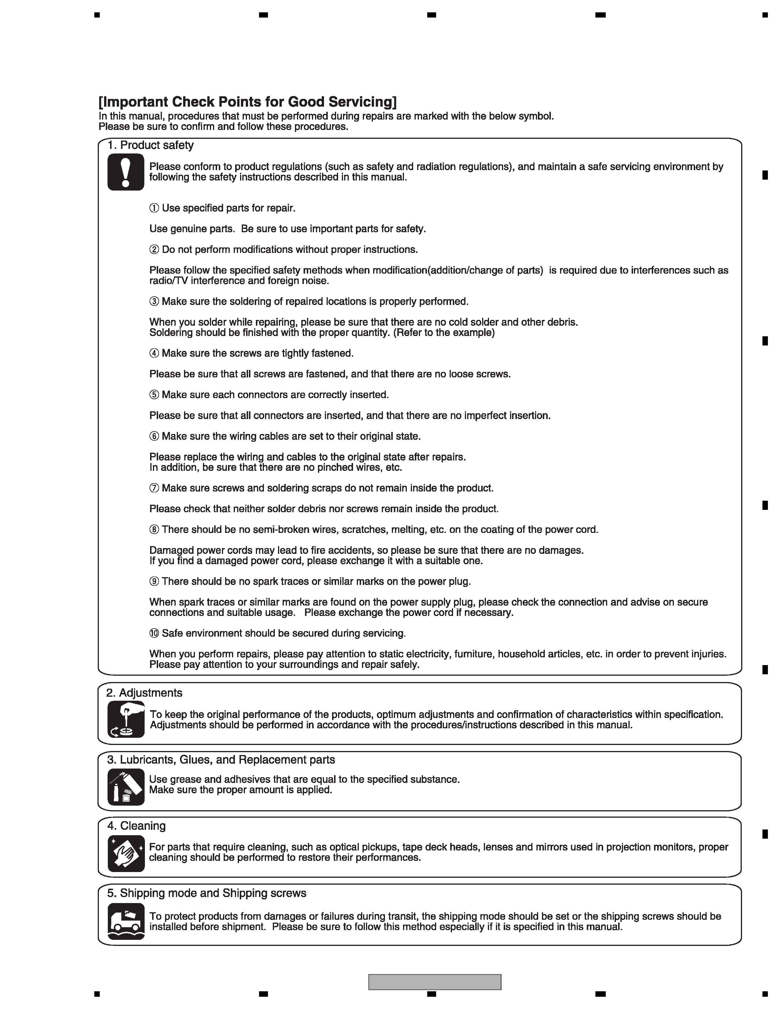
For details, refer to "Important Check Points for good servicing".
T-ZZV SEPT. 2007 printed in Japan

SX-LX70SW
2
12
34
1
234
C
D
F
A
B
E
SAFETY INFORMATION
This service manual is intended for qualified service technicians; it is not meant for the casual
do-it-yourselfer. Qualified technicians have the necessary test equipment and tools, and have been
trained to properly and safely repair complex products such as those covered by this manual.
Improperly performed repairs can adversely affect the safety and reliability of the product and may
void the warranty. If you are not qualified to perform the repair of this product properly and safely, you
should not risk trying to do so and refer the repair to a qualified service technician.
SX-LX70SW
3
56
7
8
56
7
8
C
D
F
A
B
E

SX-LX70SW
4
12
34
1
234
C
D
F
A
B
E
CONTENTS
SAFETY INFORMATION ..................................................................................................................................... 2
1. SERVICE PRECAUTIONS ............................................................................................................................... 5
2. SPECIFICATIONS ............................................................................................................................................ 6
2.1 ACCESSORIES ......................................................................................................................................... 6
2.2 SPECIFICATIONS...................................................................................................................................... 7
2.3 PANEL FACILITIES .................................................................................................................................... 8
3. BASIC ITEMS FOR SERVICE........................................................................................................................ 12
3.1 CHECK POINTS AFTER SERVICING..................................................................................................... 12
3.2 PCB LOCATIONS .................................................................................................................................... 13
3.3 JIGS LIST ................................................................................................................................................ 14
3.4 CLEANING............................................................................................................................................... 14
4. BLOCK DIAGRAM.......................................................................................................................................... 16
4.1 OVERALL WIRING CONNECTION DIAGRAM ....................................................................................... 16
4.2 OVERALL BLOCK DIAGRAM.................................................................................................................. 18
5. DIAGNOSIS.................................................................................................................................................... 20
5.1 HDMI TROUBLESHOOTING ................................................................................................................... 20
5.2 DSP TROUBLESHOOTING..................................................................................................................... 27
5.3 CIRCUIT DESCRIPTION OF DIGITAL AMP. SECTION .......................................................................... 42
5.4 SPECIFICATIONS FOR THE PROTECTION CIRCUITS FOR THE DIGITAL AMPLIFIER ..................... 43
5.5 CONDITIONS FOR SWITCHING THE ROTAIONS SPEED OF THE FAN.............................................. 44
5.6 ERROR LIST............................................................................................................................................ 45
6. SERVICE MODE ............................................................................................................................................ 49
6.1 TEST MODE ............................................................................................................................................ 49
6.2 SERVICE TEST MODE ........................................................................................................................... 51
7. DISASSEMBLY............................................................................................................................................... 54
8. EACH SETTING AND ADJUSTMENT ........................................................................................................... 59
8.1 ADJUSTMENT ......................................................................................................................................... 59
8.2 HOW TO UPDATE THE FLASH ROMS FOR VARIOUS MICROCOMPUTERS...................................... 59
8.3 HOW TO UPDATE THE DSP FLASH ROM BY PLAYING BACK A CD................................................... 61
9. EXPLODED VIEWS AND PARTS LIST.......................................................................................................... 64
9.1 PACKING (SX-LX70SW) .......................................................................................................................... 64
9.2 PACKING (AS-LX70)................................................................................................................................ 66
9.3 EXTERIOR SECTION.............................................................................................................................. 68
9.4 RECEIVER UNIT ..................................................................................................................................... 70
9.5 DISPLAY UNIT ......................................................................................................................................... 72
9.6 REMOTE CONTROL ............................................................................................................................... 74
10. SCHEMATIC DIAGRAM ............................................................................................................................... 76
10.1 MAIN ASSY (1/7) ................................................................................................................................... 76
10.2 MAIN ASSY (2/7) ................................................................................................................................... 78
10.3 MAIN ASSY (3/7) ................................................................................................................................... 80
10.4 MAIN ASSY (4/7) ................................................................................................................................... 82
10.5 MAIN ASSY (5/7) ................................................................................................................................... 84
10.6 MAIN ASSY (6/7) ................................................................................................................................... 86
10.7 MAIN ASSY (7/7) ................................................................................................................................... 88
10.8 AMP ASSY (1/2) .................................................................................................................................... 90
10.9 AMP ASSY (2/2) .................................................................................................................................... 92
10.10 CONNECTION and EARTH ASSYS .................................................................................................... 94
10.11 HDMI ASSY (1/2) ................................................................................................................................. 96
10.12 HDMI ASSY (2/2) ................................................................................................................................. 98
10.13 AINB ASSY ........................................................................................................................................ 100
10.14 FL, REMOCON and BTOB ASSYS ................................................................................................... 102
10.15 POWER SUPPLY UNIT...................................................................................................................... 104
11. PCB CONNECTION DIAGRAM ................................................................................................................. 107
11.1 MAIN ASSY ......................................................................................................................................... 108
11.2 AMP ASSY........................................................................................................................................... 112
11.3 CONNECTION ASSY .......................................................................................................................... 116
11.4 EARTH ASSYS .................................................................................................................................... 117
11.5 HDMI ASSY ......................................................................................................................................... 118
11.6 BTOB ASSY ......................................................................................................................................... 122
11.7 AINB ASSY .......................................................................................................................................... 123
11.8 FL ASSY .............................................................................................................................................. 125
11.9 POWER SUPPLY UNIT........................................................................................................................ 127
12. PCB PARTS LIST ....................................................................................................................................... 129

SX-LX70SW
5
56
7
8
56
7
8
C
D
F
A
B
E
1. SERVICE PRECAUTIONS
CAUTION
Ask users to bring both subwoofer receiver and the display unit together when servicing.
NOTES ON SOLDERING
· For environmental protection, lead-free solder is used on the printed circuit boards mounted in this unit.
Be sure to use lead-free solder and a soldering iron that can meet specifications for use with lead-free solders for repairs
accompanied by reworking of soldering.
· Compared with conventional eutectic solders, lead-free solders have higher melting points, by approximately 40
°C.
Therefore, for lead-free soldering, the tip temperature of a soldering iron must be set to around 373
°C in general, although
the temperature depends on the heat capacity of the PC board on which reworking is required and the weight of the tip of
the soldering iron.
Do NOT use a soldering iron whose tip temperature cannot be controlled.
Compared with eutectic solders, lead-free solders have higher bond strengths but slower wetting times and higher melting
temperatures (hard to melt/easy to harden).
The following lead-free solders are available as service parts:
· Parts numbers of lead-free solder:
GYP1006 1.0 in dia.
GYP1007 0.6 in dia.
GYP1008 0.3 in dia.