ORDER NO.
PIONEER CORPORATION 4-1, Meguro 1-chome, Meguro-ku, Tokyo 153-8654, Japan
PIONEER ELECTRONICS (USA) INC. P.O. Box 1760, Long Beach, CA 90801-1760, U.S.A.
PIONEER EUROPE NV Haven 1087, Keetberglaan 1, 9120 Melsele, Belgium
PIONEER ELECTRONICS ASIACENTRE PTE. LTD. 253 Alexandra Road, #04-01, Singapore 159936
PIONEER CORPORATION 2006
UP
DOWN
MULTI JOG
MASTER
VOLUME
ENTER
AUDIO MULTI-CHANNEL RECEIVER
SX-316
STANDBY/ON
PHONES
FRONT
AUDIO INPUT
DVD/LD
TV/SAT
DVR
CD
CD-R/TAPE/MD
FRONT AUDIO
FM
AM
STANDARD
MIDNIGHT/
LOUDNESS
ADVANCED
SURR
ST/DIRECT/
AUTO SURR
LISTENING MODE
QUICK
SETUP
SETUP
RETURN
MUTE
TONE
PTY
SEARCH
SLEEP
TUNER
EDIT
EON
MODE
MULTI JOG
TUNING
STATION
MPX
VSB
MODE
DIALOGUE
ENHANCEMENT
SX-316-S
RRV3330
AUDIO MULTI-CHANNEL RECEIVER
SX-316-S
THIS MANUAL IS APPLICABLE TO THE FOLLOWINGMODEL(S) AND TYPE(S).
Model
Type
Power Requirement
Remarks
SX-316-S
KUCXJ
AC 120 V
SX-316-S
MYXJ5
AC 220 V to 230 V
For details, refer to "Important Check Points for Good Servicing".
T-ZZK MAY 2006 printed in Japan
SX-316-S
2
12
34
12
3
4
C
D
F
A
B
E
SAFETY INFORMATION
This service manual is intended for qualified service technicians; it is not meant for the casual
do-it-yourselfer. Qualified technicians have the necessary test equipment and tools, and have been
trained to properly and safely repair complex products such as those covered by this manual.
Improperly performed repairs can adversely affect the safety and reliability of the product and may
void the warranty. If you are not qualified to perform the repair of this product properly and safely, you
should not risk trying to do so and refer the repair to a qualified service technician.
WARNING
This product contains lead in solder and cer tain electrical par ts contain chemicals which are known to the state of California to
cause cancer, bir th defects or other reproductive harm.
Health & Safety Code Section 25249.6 Proposition 65
NOTICE
(FOR CANADIAN MODEL ONLY)
Fuse symbols
(fast operating fuse)
and/or
(slow operating fuse) on PCB indicate that replacement
parts must be of identical designation.
REMARQUE
(POUR MODÈLE CANADIEN SEULEMENT)
Les symboles de fusible
(fusible de type rapide)
et/ou
(fusible de type lent) sur CCI indiquent que
les pièces de remplacement doivent avoir la même désignation.
ANY MEASUREMENTS NOT WITHIN THE
LIMITS OUTLINED ABOVE ARE INDICATIVE
OF A POTENTIAL SHOCK HAZARD AND
MUST BE CORRECTED BEFORE RETURN-
ING THE APPLIANCE TO THE CUSTOMER.
2. PRODUCT SAFETY NOTICE
Many electrical and mechanical parts in the appliance
have special safety related character istics. These are
often not evident
from visual
inspection nor the
protection afforded by them necessarily can be obtained
by using replacement components rated for voltage,
wattage, etc. Replacement par ts which have these
special safety character istics are identified in this
Service Manual.
Electr ical components having such features are
identified by marking with a
on the schematics and
on the parts list in this Service Manual.
The use of a substitute replacement component which
does not have the same safety characteristics as the
PIONEER recommended replacement one, shown in the
parts list in this Service Manual, may create shock, fire,
or other hazards.
Product Safety is continuously under review and new
instructions are issued from time to time. For the latest
infor mation, always consult the current PIONEER
Service Manual. A subscription to, or
additional copies
of, PIONEER Ser vice Manual may be obtained at a
nominal charge from PIONEER.
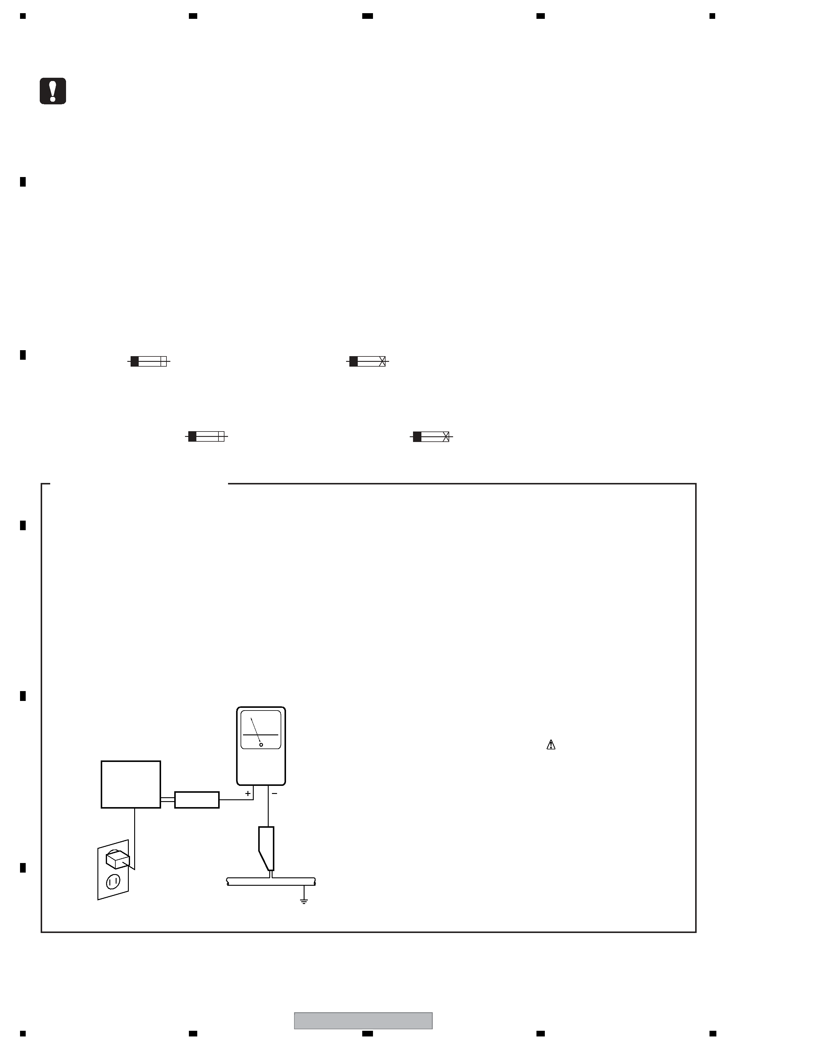
(FOR USA MODEL ONLY)
1. SAFETY PRECAUTIONS
The following check should be perfor med for the
continued protection of the customer and ser vice
technician.
LEAKAGE CURRENT CHECK
Measure leakage current to a known ear th ground
(water pipe, conduit, etc.) by connecting a leakage
current tester such as Simpson Model 229-2 or
equivalent between the ear th ground and all exposed
metal par ts of the appliance (input/output ter minals,
screwheads, metal overlays, control shaft, etc.). Plug
the AC line cord of the appliance directly into a 120V
AC 60 Hz outlet and turn the AC power switch on. Any
current measured must not exceed 0.5 mA.
Device
under
test
Leakage
current
tester
Earth
ground
Reading should
not be above
0.5 mA
Also test with
plug reversed
(Using AC adapter
plug as required)
Test all
exposed metal
surfaces
AC Leakage Test
SX-316-S
3
56
78
56
7
8
C
D
F
A
B
E
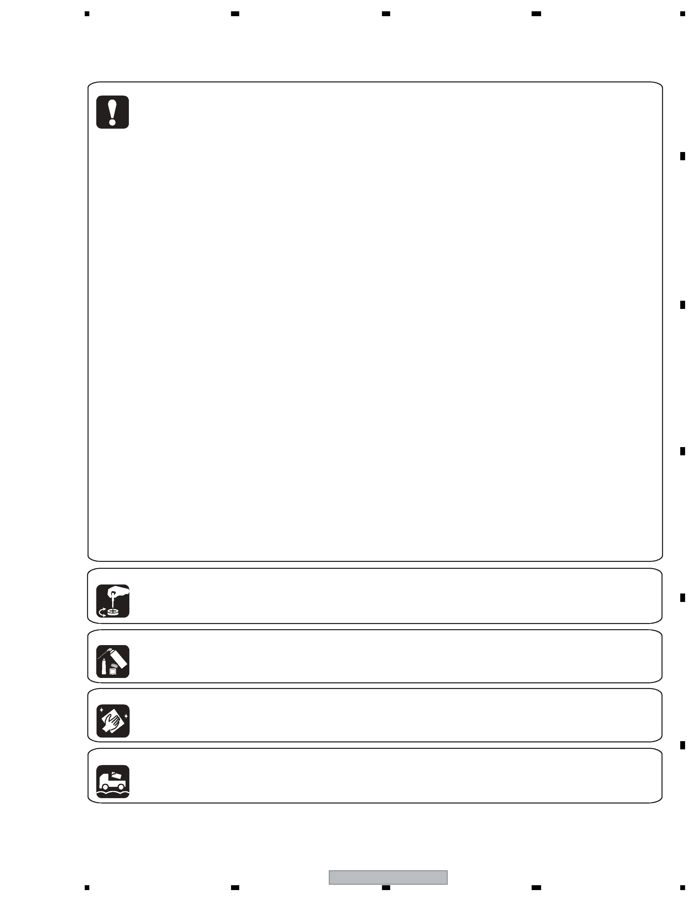
[Important Check Points for Good Servicing]
In this manual, procedures that must be performed during repairs are marked with the below symbol.
Please be sure to confirm and follow these procedures.
1. Product safety
Please conform to product regulations (such as safety and radiation regulations), and maintain a safe servicing environment by
following the safety instructions described in this manual.
1 Use specified parts for repair.
Use genuine parts. Be sure to use important parts for safety.
2 Do not perform modifications without proper instructions.
Please follow the specified safety methods when modification(addition/change of parts) is required due to interferences such as
radio/TV interference and foreign noise.
3 Make sure the soldering of repaired locations is properly performed.
When you solder while repairing, please be sure that there are no cold solder and other debris.
Soldering should be finished with the proper quantity. (Refer to the example)
4 Make sure the screws are tightly fastened.
Please be sure that all screws are fastened, and that there are no loose screws.
5 Make sure each connectors are correctly inserted.
Please be sure that all connectors are inserted, and that there are no imperfect insertion.
6 Make sure the wiring cables are set to their original state.
Please replace the wiring and cables to the original state after repairs.
In addition, be sure that there are no pinched wires, etc.
7 Make sure screws and soldering scraps do not remain inside the product.
Please check that neither solder debris nor screws remain inside the product.
8 There should be no semi-broken wires, scratches, melting, etc. on the coating of the power cord.
Damaged power cords may lead to fire accidents, so please be sure that there are no damages.
If you find a damaged power cord, please exchange it with a suitable one.
9 There should be no spark traces or similar marks on the power plug.
When spark traces or similar marks are found on the power supply plug, please check the connection and advise on secure
connections and suitable usage. Please exchange the power cord if necessary.
0 Safe environment should be secured during servicing.
When you perform repairs, please pay attention to static electricity, furniture, household articles, etc. in order to prevent injuries.
Please pay attention to your surroundings and repair safely.
2. Adjustments
To keep the original performance of the products, optimum adjustments and confirmation of characteristics within specification.
Adjustments should be performed in accordance with the procedures/instructions described in this manual.
4. Cleaning
For parts that require cleaning, such as optical pickups, tape deck heads, lenses and mirrors used in projection monitors, proper
cleaning should be performed to restore their performances.
3. Lubricants, Glues, and Replacement parts
Use grease and adhesives that are equal to the specified substance.
Make sure the proper amount is applied.
5. Shipping mode and Shipping screws
To protect products from damages or failures during transit, the shipping mode should be set or the shipping screws should be
installed before shipment. Please be sure to follow this method especially if it is specified in this manual.

SX-316-S
4
12
34
12
3
4
C
D
F
A
B
E
CONTENTS
SAFETY INFORMATION ..................................................................................................................................... 2
1. SPECIFICATIONS ............................................................................................................................................ 5
2. EXPLODED VIEWS AND PARTS LIST ............................................................................................................ 6
2.1 PACKING ................................................................................................................................................... 6
2.2 EXTERIOR SECTION................................................................................................................................ 8
2.3 FRONT PANEL SECTION ....................................................................................................................... 10
3. BLOCK DIAGRAM AND SCHEMATIC DIAGRAM ..........................................................................................12
3.1 BLOCK DIAGRAM ................................................................................................................................... 12
3.2 OVERALL WIRING CONNECTION DIAGRAM........................................................................................ 14
3.3 MAIN ASSY (1/3) ..................................................................................................................................... 16
3.4 MAIN ASSY (2/3) ..................................................................................................................................... 18
3.5 MAIN ASSY (3/3) ..................................................................................................................................... 20
3.6 DSP ASSY (1/2)....................................................................................................................................... 22
3.7 DSP ASSY (2/2)....................................................................................................................................... 24
3.8 POWER PACK (1/2), TRANS 2 and TRANS 3 ASSYS ............................................................................ 26
3.9 POWER PACK (2/2) and HEADPHONE ASSYS ..................................................................................... 28
3.10 FRONT DISPLAY, R. ENCODER and POWER KEY ASSYS ................................................................ 30
3.11 TRANS 4, REGULATOR and DIGITAL IN ASSYS ................................................................................. 32
3.12 FRONT INPUT, PRIMARY and TRANS 1 ASSYS ................................................................................. 33
4. PCB CONNECTION DIAGRAM ..................................................................................................................... 34
4.1 REGULATOR and DIGITAL IN ASSYS .................................................................................................... 35
4.2 MAIN and FRONT INPUT ASSYS ........................................................................................................... 36
4.3 DSP ASSY ............................................................................................................................................... 40
4.4 POWER PACK ASSY............................................................................................................................... 44
4.5 TRANS2, TRANS3, TRANS4 and TRANS1 ASSYS ................................................................................ 48
4.6 HEAD PHONE, FRONT DISPLY, R. ENCODER and POWER KEY ASSYS ........................................... 50
4.7 PRIMARY ASSY ...................................................................................................................................... 54
5. PCB PARTS LIST ........................................................................................................................................... 56
6. ADJUSTMENT ............................................................................................................................................... 73
7. GENERAL INFORMATION ............................................................................................................................. 74
7.1 DIAGNOSIS ............................................................................................................................................. 74
7.1.1 DISASSEMBLY.................................................................................................................................. 74
7.2 PARTS...................................................................................................................................................... 77
7.2.1 IC ....................................................................................................................................................... 77
7.3 EXPLANATION ........................................................................................................................................ 85
7.3.1 DETECTION CIRCUIT ...................................................................................................................... 85
7.3.2 AMPLIFIER SYSTEM PROTECTION OPERATION SPECIFICATION.............................................. 87
7.3.3 AMPLIFIER FAILURE DIAGNOSIS FLOW CHART .......................................................................... 89
8. PANEL FACILITIES ........................................................................................................................................ 90
SX-316-S
5
56
78
56
7
8
C
D
F
A
B
E
1. SPECIFICATIONS
Amplifier section
Continuous Power Output (stereo)
Front . . . . . 100 W (DIN 1 kHz, THD, 1.0 %, 8
)
Power Output (surround)
Front
. . . . 100 W per channel (1 kHz, 1.0 % THD, 8
)
Center . . . . . . . . 100 W (1 kHz, 1.0 % THD, 8
)
Surround . . . . . . . . . . . . . . . . 100 W per channel
(1 kHz, 1.0 % THD, 8
)
Subwoofer . . . .100 W (100 Hz, 1.0 % THD, 8
)
RMS Power Output
Front
. . . . .130 W per channel (1 kHz, 10 % THD, 8
)
Center . . . . . . . . .130 W (1 kHz, 10 % THD, 8
)
Surround . . . . . . . . . . . . . . . . 130 W per channel
(1 kHz, 10 % THD, 8
)
Subwoofer . . . . 130 W (100 Hz, 10 % THD, 8
)
FM Tuner Section
Frequency Range . . . . . . . 87.5 MHz to 108 MHz
Antenna Input. . . . . . . . . . . . . . 75
unbalanced
AM Tuner Section
Frequency Range . . . . . . . 531 kHz to 1 602 kHz
Antenna . . . . . . . . . . . . . . . . . . . . . Loop antenna
Miscellaneous
Power requirements
. . . . . . . . . . . . . AC 220V to 230 V, 50 Hz/ 60 Hz
Power consumption. . . . . . . . . . . . . . . . . . 320 W
In standby. . . . . . . . . . . . . . . . . . . . . . . . 0.5 W
Dimensions
. . . . . . 420 mm (W) x 158 mm (H) x 348 mm (D)
Weight (without package). . . . . . . . . . . . . . 8.5 kg
Furnished Parts
AM loop antenna . . . . . . . . . . . . . . . . . . . . . . . 1
FM wire antenna . . . . . . . . . . . . . . . . . . . . . . . 1
AA size IEC R6 dry cell batteries (to confirm
system operation). . . . . . . . . . . . . . . . . . . . . . . 2
Remote control. . . . . . . . . . . . . . . . . . . . . . . . . 1
Warranty card. . . . . . . . . . . . . . . . . . . . . . . . . . 1
Operating instructions
Manufactured under license from Dolby Laboratories.
"Dolby", "Pro Logic", and the double-D symbol are
trademarks of Dolby Laboratories.
"DTS" and "DTS 96/24" are trademarks of Digital Theater
Systems, Inc.
Note
Specifications and the design are subject
to possible modifications without notice,
due to improvements.
SX-316-S/MYXJ5
SX-316-S/KUCXJ
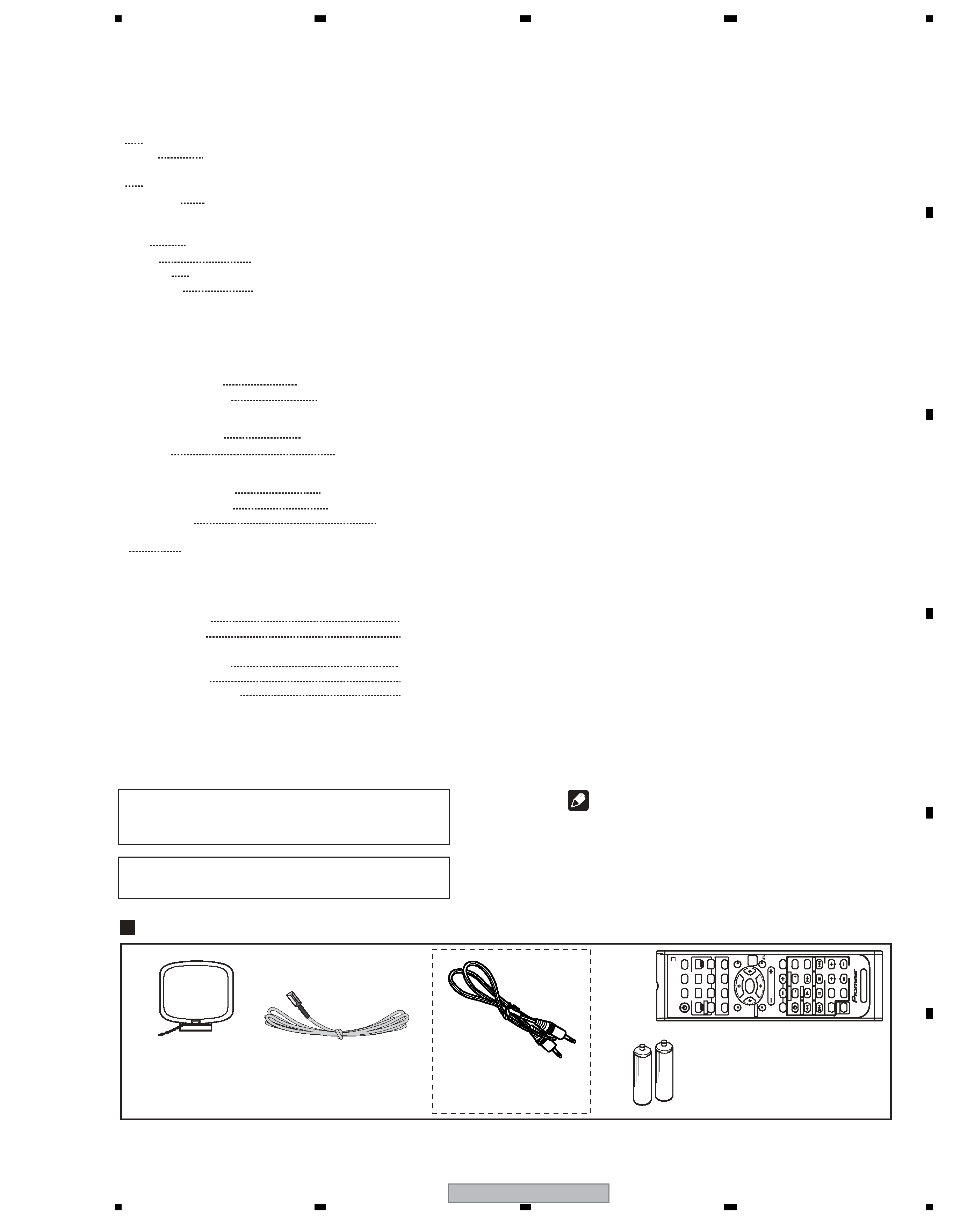
Accessories
Remote control
(XXD3108)
AM loop antenna
(ATB7013)
FM wire antenna
(ADH7030)
AA size IEC R6
Dry cell batteries (x2)
Mini-plug audio cable
(KUCXJ : ADE7059)
(L=1m)
INPUT
SELECTOR
RECEIVER
STANDARD
ADV.SURR
STEREO
MIDNIGHT/ LOUDNESS
TOP
MENU
SETUP
RETURN
S.RETRIEVER
TUNER
EDIT
ONE TOUCH COPY
HDD
DVD
DVD/DVR
TUNING
DISPLAY
CLASS
MPX
STATION
DVD/DVR
TUNER
AUDIO
SUBTITLE
MUTE
EFFECT/CH
SEL
LEVEL
ENTER
RECEIVER
VOLUME
SLEEP
F.AUDIO
DVR
DVD
CD-R
AM
FM
CD
RECEIVER
TV
DIMMER
ANALOG
ATT
MENU
DIALOG
E
GUIDE
REC
TIMER
REC
INFO
REC
STOP
JUKEBOX
CH
CH
SHIFT
Amplifier section
Continuous power output
Front
100 W per channel* (200 Hz to 20 kHz, 0.7 %**, 8
)
Center
100 W*(200 Hz to 20 kHz, 0.7 %**, 8
)
Surround
100 W per channel*(200 Hz to 20 kHz, 0.7 %**, 8
)
Subwoofer
100 W*(45 Hz to 200 kHz, 0.7 %**, 8
)
RMS Power Output
Front
144 W per channel (1 kHz, THD, 10 %, 8
)
Center
144 W (1 kHz, THD, 10 %, 8
)
Surround
144 W per channel (1 kHz, THD, 10 %, 8
)
Subwoofer
144 W (1 kHz, THD, 10 %, 8
)
* Measured pursuant to the Federal Trade Commission's Trade
Regulation rule on Power Output Claims for Amplifiers.
** Measured by Audio Spectrum Analyzer.
FM Tuner Section
Frequency Range
87.5 MHz to 108 MHz
Antenna Input (DIN)
75
unbalanced
AM Tuner Section
Frequency Range
530 kHz to 1 700 kHz
Antenna
Loop antenna
Miscellaneous
Power requirements
AC 120 V / 60 Hz
Power consumption
320 W / 420 VA
In standby
0.5 W
Dimensions
16 9/16 in. (W) x 6 1/4 in. (H) x 13 11/16 in.(D)
420 mm (W) x 158 mm(H) x 348 mm(D)
Weight (without package)
19.0 lb (8.6 kg)
Furnished Parts
AM loop antenna
1
FM wire antenna
1
AA size IEC R6 dry cell batteries (to confirm
system operation)
2
Remote control
1
Mini-plug audio cable
1
Operating instructions
Note
Specifications and the design are subject to possible
modifications without notice, due to improvements.