ORDER NO.
PIONEER CORPORATION 4-1, Meguro 1-chome, Meguro-ku, Tokyo 153-8654, Japan
PIONEER ELECTRONICS (USA) INC. P.O. Box 1760, Long Beach, CA 90801-1760, U.S.A.
PIONEER EUROPE NV Haven 1087, Keetberglaan 1, 9120 Melsele, Belgium
PIONEER ELECTRONICS ASIACENTRE PTE. LTD. 253 Alexandra Road, #04-01, Singapore 159936
PIONEER CORPORATION 2001
RRV2540
POWERED SPEAKER SYSTEM
S-W8
1. SAFETY INFORMATION ...................................... 2
2. EXPLODED VIEWS AND PARTS LIST ................ 3
3. SCHEMATIC DIAGRAM ........................................ 8
4. PCB CONNECTION DIAGRAM .......................... 11
5. PCB PARTS LIST ............................................... 18
6. ADJUSTMENT .................................................... 19
CONTENTS
7. GENERAL INFORMATION ................................ 20
7.1 DISASSEMBLY ........................................... 20
8. PANEL FACILITIES AND SPECIFICATIONS .... 21
THIS MANUAL IS APPLICABLE TO THE FOLLOWING MODEL(S) AND TYPE(S).
Type
Model
S-W8
LBXTW/E
WLXTW/E
AC110 120V
AC220 240V
Power Requirement
Remarks
T ZZV SEPT. 2001 Printed in Japan
S-W8
2
1. SAFETY INFORMATION
This service manual is intended for qualified service technicians; it is not meant for the casual
do-it-yourselfer. Qualified technicians have the necessary test equipment and tools, and have been
trained to properly and safely repair complex products such as those covered by this manual.
Improperly performed repairs can adversely affect the safety and reliability of the product and may
void the warranty. If you are not qualified to perform the repair of this product properly and safely, you
should not risk trying to do so and refer the repair to a qualified service technician.
WARNING
This product contains lead in solder and certain electrical parts contain chemicals which are known to the state of California to
cause cancer, birth defects or other reproductive harm.
Health & Safety Code Section 25249.6 Proposition 65
NOTICE
(FOR CANADIAN MODEL ONLY)
Fuse symbols
(fast operating fuse)
and/or
(slow operating fuse) on PCB indicate that replacement
parts must be of identical designation.
REMARQUE
(POUR MODÈLE CANADIEN SEULEMENT)
Les symboles de fusible
(fusible de type rapide)
et/ou
(fusible de type lent) sur CCI indiquent que
les pièces de remplacement doivent avoir la même désignation.
ANY MEASUREMENTS NOT WITHIN THE
LIMITS OUTLINED ABOVE ARE INDICATIVE
OF A POTENTIAL SHOCK HAZARD AND
MUST BE CORRECTED BEFORE RETURN-
ING THE APPLIANCE TO THE CUSTOMER.
2. PRODUCT SAFETY NOTICE
Many electrical and mechanical parts in the appliance
have special safety related characteristics. These are
often not evident
from visual
inspection nor the
protection afforded by them necessarily can be obtained
by using replacement components rated for voltage,
wattage, etc. Replacement parts which have these
special safety characteristics are identified in this
Service Manual.
Electrical components having such features are
identified by marking with a
on the schematics and
on the parts list in this Service Manual.
The use of a substitute replacement component which
does not have the same safety characteristics as the
PIONEER recommended replacement one, shown in the
parts list in this Service Manual, may create shock, fire,
or other hazards.
Product Safety is continuously under review and new
instructions are issued from time to time. For the latest
information, always consult the current PIONEER
Service Manual. A subscription to, or
additional copies
of, PIONEER Service Manual may be obtained at a
nominal charge from PIONEER.
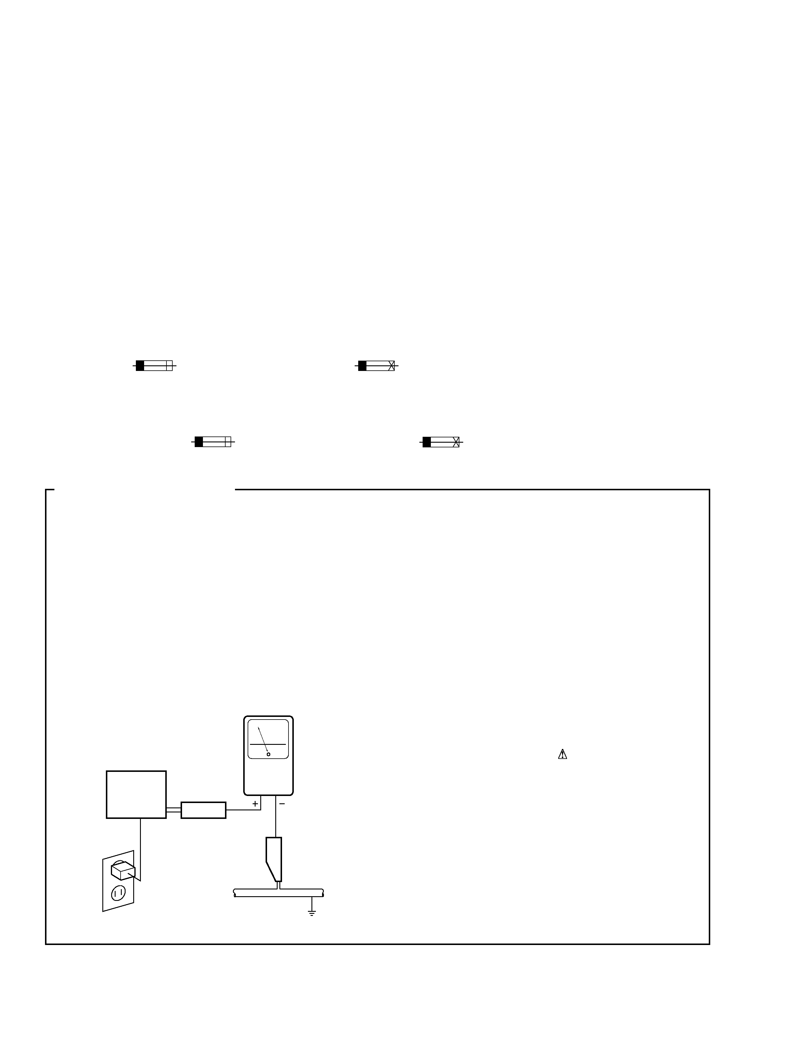
(FOR USA MODEL ONLY)
1. SAFETY PRECAUTIONS
The following check should be performed for the
continued protection of the customer and service
technician.
LEAKAGE CURRENT CHECK
Measure leakage current to a known earth ground
(water pipe, conduit, etc.) by connecting a leakage
current tester such as Simpson Model 229-2 or
equivalent between the earth ground and all exposed
metal parts of the appliance (input/output terminals,
screwheads, metal overlays, control shaft, etc.). Plug
the AC line cord of the appliance directly into a 120V
AC 60 Hz outlet and turn the AC power switch on. Any
current measured must not exceed 0.5 mA.
Device
under
test
Leakage
current
tester
Earth
ground
Reading should
not be above
0.5 mA
Also test with
plug reversed
(Using AC adapter
plug as required)
Test all
exposed metal
surfaces
AC Leakage Test
S-W8
3
2. EXPLODED VIEWS AND PARTS LIST
Parts marked by "NSP" are generally unavailable because they are not in our Master Spare Parts List.
The
mark found on some component parts indicates the importance of the safety factor of the part.
Therefore, when replacing, be sure to use parts of identical designation.
Screws adjacent to
mark on product are used for disassembly.
NOTES:
Mark No.
Description
Part No.
Mark No.
Description
Part No.
1
Opearting Instructions
SRA1377
(English,Spanish,Chinese)
2
Speaker Cord
4999A-869
3
RCA Plug Cord
VRC0001-006
4
Ground Cord
4999A-868
5
Protector L
ITF0064C001
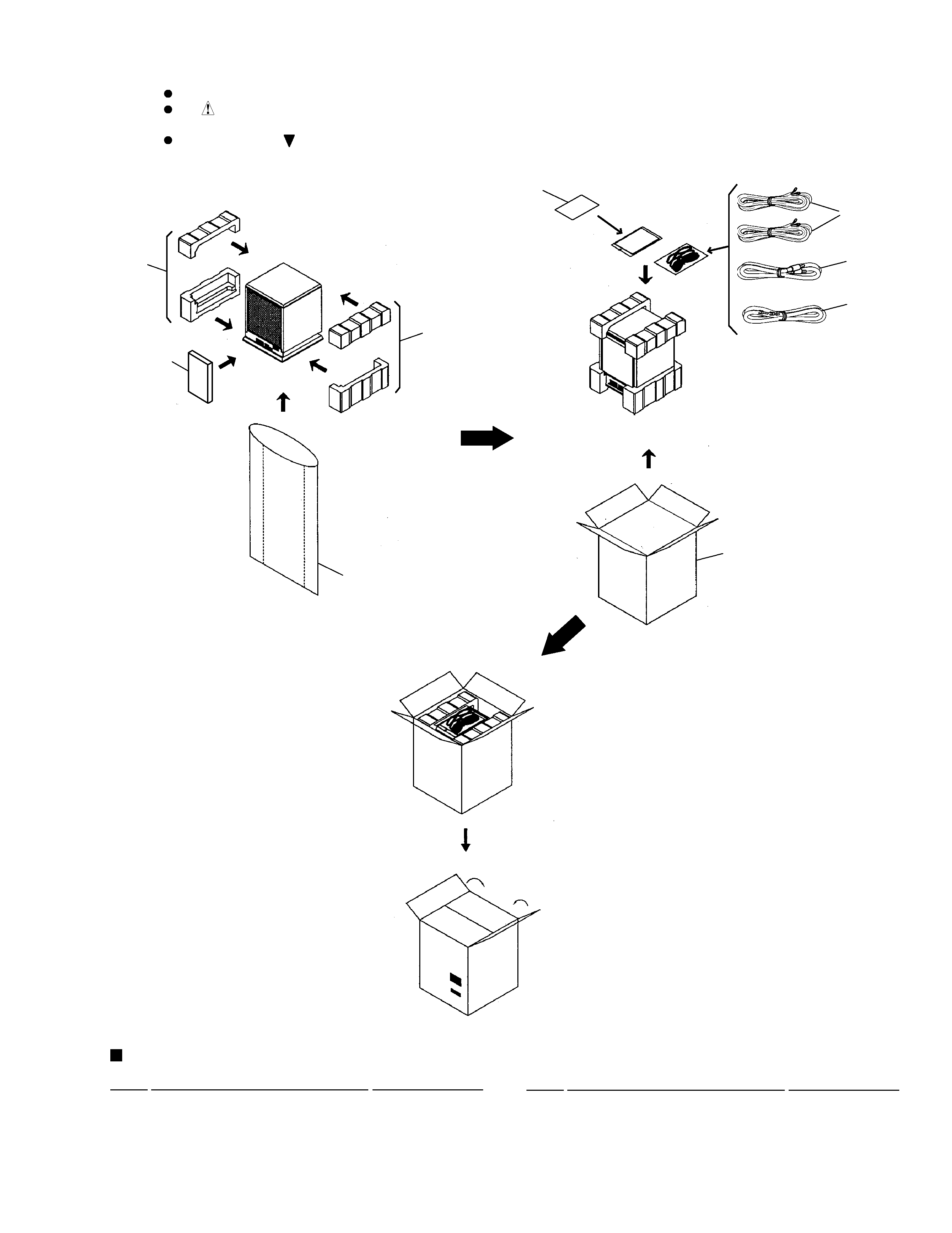
2.1 PACKING
PACKING PARTS LIST
1
6
5
7
9
8
Note : The parts without numbering
are not supplied as service parts.
2
3
4
6
Protector R
ITF0065C001
7
Protector Front
ITF0078C001
8
Packing Case (LBXTW/E type) ICC0027C003
8
Packing Case (WLXTW/E type) ICC0027C002
9
Polyethylene Bag
IVP0001-132
S-W8
4
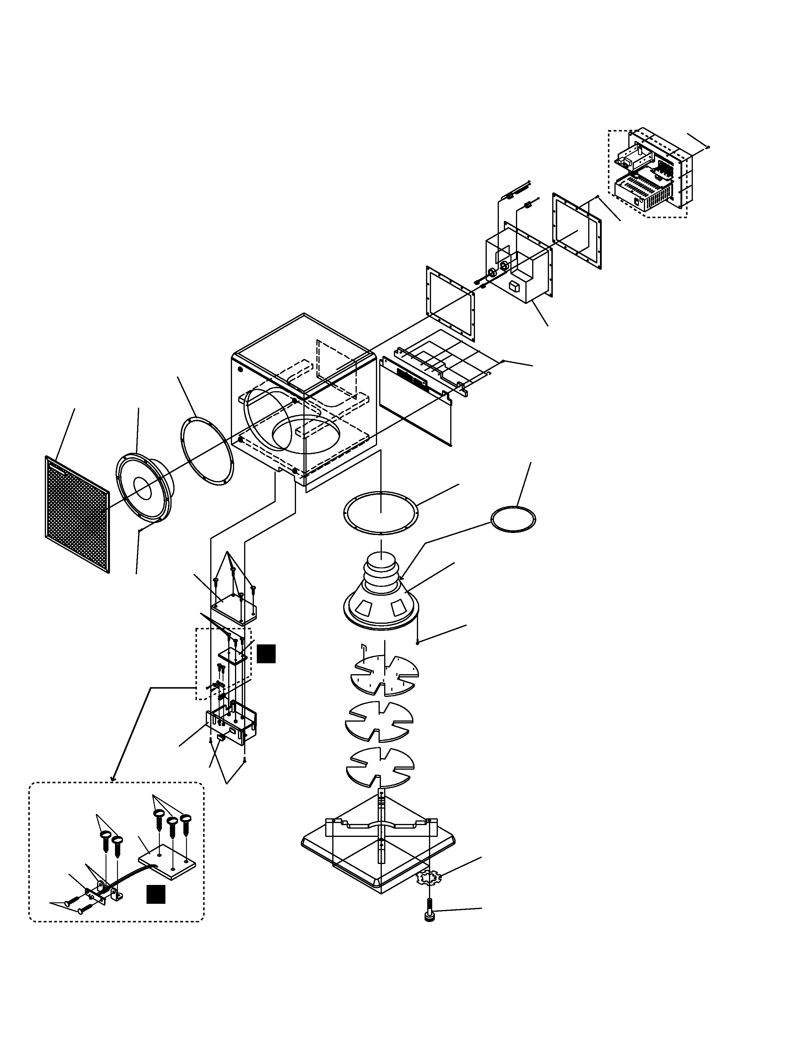
2.2 EXTERIOR
3
9
13
5
1
6
15
8
5
5
18
1
1
19
10
14
11
7
4
17
4
20 (4pcs)
12
Amp Cover
Refer to "2.3 AMP ASSY".
12
12
16
13
C
C
Note : The parts without numbering
are not supplied as service parts.
Note :
The No.1 Assy consists
of 2 PCB boards.

S-W8
5
Mark No.
Description
Part No.
1
POWER SW ASSY
APE0485-031
2
· · · · · · · · ·
3
Grille Assy
AFA00160001
4
Sponge
IVE0043C001
5
Screw
PBZ30P060FZK
6
Rubber Bush
BRB0003-002
7
Screw
PBZ30P080FZK
8
Control Box
BPC0010M001
9
Control Cover
BPC0011M001
10
Screw
BYC30P160FZK
11
Screw
HZ00016-001
12
Screw
SBA-153
13
Screw
SBA-122
14
Washer
HWT2280-210
15
Switch Rocker
MVS0001-A11
16
Speaker
A30IU50-51C
17
Passive Radiator
DC-17G
18
Bracket
GSE0093-001
19
Screw
PMZ30P060FZK
20
Craft Paper
ICT0003-001
EXTERIOR PARTS LIST