ORDER NO.
PIONEER CORPORATION 4-1, Meguro 1-chome, Meguro-ku, Tokyo 153-8654, Japan
PIONEER ELECTRONICS SERVICE, INC. P.O. Box 1760, Long Beach, CA 90801-1760, U.S.A.
PIONEER EUROPE NV Haven 1087, Keetberglaan 1, 9120 Melsele, Belgium
PIONEER ELECTRONICS ASIACENTRE PTE. LTD. 253 Alexandra Road, #04-01, Singapore 159936
PIONEER CORPORATION 2000
c
S-W80S
RRV2407
1. SAFETY INFORMATION ...................................... 2
2. EXPLODED VIEWS AND PARTS LIST ................ 3
3. SCHEMATIC DIAGRAM ....................................... 6
4. PCB CONNECTION DIAGRAM ............................ 8
5. PCB PARTS LIST ............................................... 12
6. ADJUSTMENT .................................................... 12
CONTENTS
7. GENERAL INFORMATION ................................ 13
7.1 DISASSEMBLY/ASSEMBLY ....................... 13
8. PANEL FACILITIES AND SPECIFICATIONS .... 14
T ZZV NOV. 2000 Printed in Japan
POWERED SPEAKER SYSTEM
Type
Model
Power Requirement
Remarks
S-W80S
MLXCN
AC220-230V
THIS MANUAL IS APPLICABLE TO THE FOLLOWING MODEL(S) AND TYPE(S).
STANDBY/
POWER ON
POWER
2
S-W80S
1. SAFETY INFORMATION
This service manual is intended for qualified service technicians ; it is not meant for the casual do-it-
yourselfer. Qualified technicians have the necessary test equipment and tools, and have been trained
to properly and safely repair complex products such as those covered by this manual.
Improperly performed repairs can adversely affect the safety and reliability of the product and may
void the warranty. If you are not qualified to perform the repair of this product properly and safely, you
should not risk trying to do so and refer the repair to a qualified service technician.
WARNING
This product contains lead in solder and certain electrical parts contain chemicals which are known to the state of California to cause
cancer, birth defects or other reproductive harm.
Health & Safety Code Section 25249.6 Proposition 65
NOTICE
(FOR CANADIAN MODEL ONLY)
Fuse symbols
(fast operating fuse) and/or
(slow operating fuse) on PCB indicate that replacement parts must
be of identical designation.
REMARQUE
(POUR MODÈLE CANADIEN SEULEMENT)
Les symboles de fusible
(fusible de type rapide) et/ou
(fusible de type lent) sur CCI indiquent que les pièces
de remplacement doivent avoir la même désignation.
ANY MEASUREMENTS NOT WITHIN THE LIMITS
OUTLINED ABOVE ARE INDICATIVE OF A POTENTIAL
SHOCK HAZARD AND MUST BE CORRECTED BEFORE
RETURNING THE APPLIANCE TO THE CUSTOMER.
2. PRODUCT SAFETY NOTICE
Many electrical and mechanical parts in the appliance
have special safety related characteristics. These are
often not evident from visual inspection nor the protection
afforded by them necessarily can be obtained by using
replacement components rated for voltage, wattage, etc.
Replacement parts which have these special safety
characteristics are identified in this Service Manual.
Electrical components having such features are identified
by marking with a
on the schematics and on the parts list
in this Service Manual.
The use of a substitute replacement component which does
not have the same safety characteristics as the PIONEER
recommended replacement one, shown in the parts list in
this Service Manual, may create shock, fire, or other hazards.
Product Safety is continuously under review and new
instructions are issued from time to time. For the latest
information, always consult the current PIONEER Service
Manual. A subscription to, or additional copies of, PIONEER
Service Manual may be obtained at a nominal charge from
PIONEER.
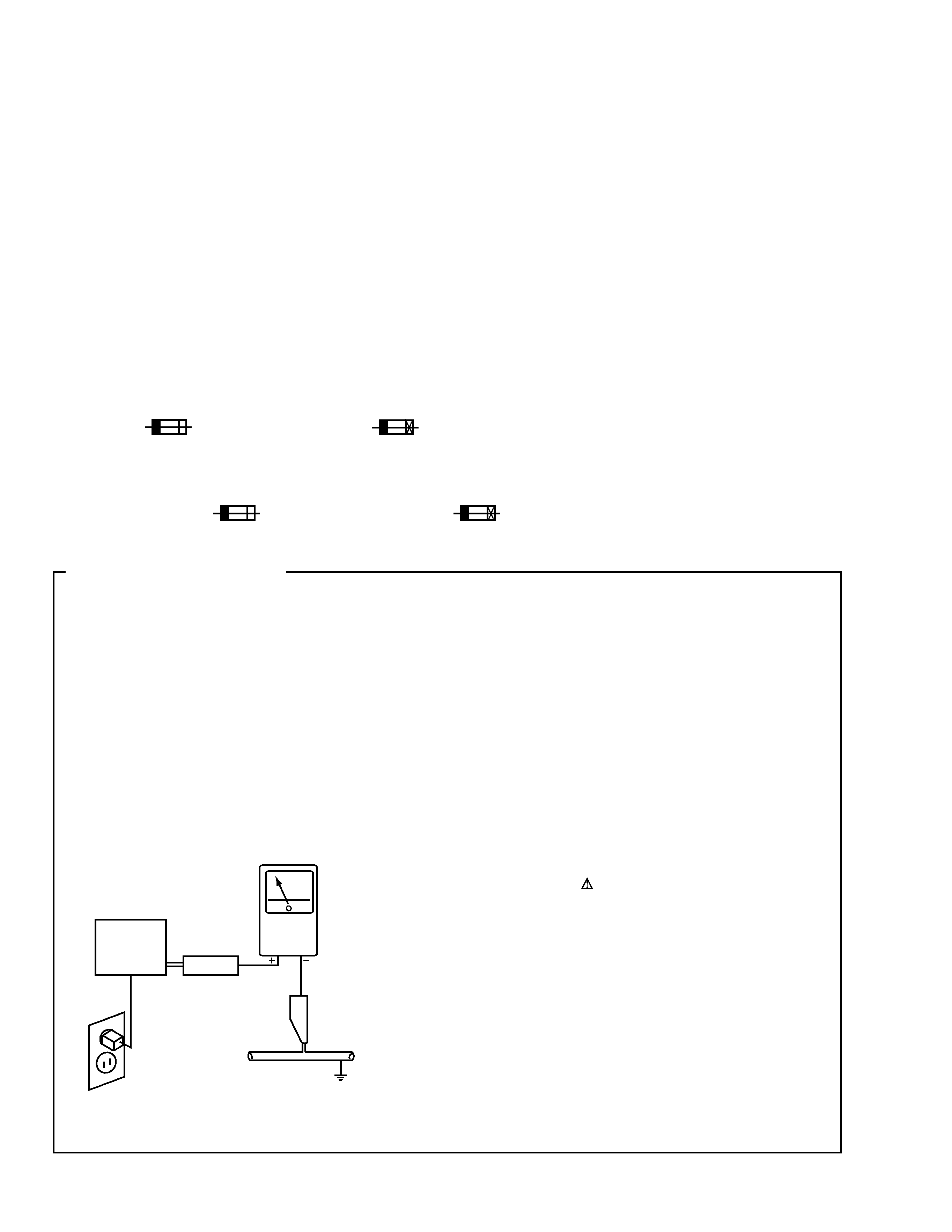
1. SAFETY PRECAUTIONS
The following check should be performed for the
continued protection of the customer and service
technician.
LEAKAGE CURRENT CHECK
Measure leakage current to a known earth ground (water
pipe, conduit, etc.) by connecting a leakage current tester
such as Simpson Model 229-2 or equivalent between the
earth ground and all exposed metal parts of the appliance
(input/output terminals, screwheads, metal overlays, control
shaft, etc.). Plug the AC line cord of the appliance directly
into a 120V AC 60Hz outlet and turn the AC power switch
on. Any current measured must not exceed 0.5mA.
(FOR USA MODEL ONLY)
Leakage
current
tester
Reading should
not be above
0.5mA
Device
under
test
Test all
exposed metal
surfaces
Also test with
plug reversed
(Using AC adapter
plug as required)
Earth
ground
AC Leakage Test
3
S-W80S
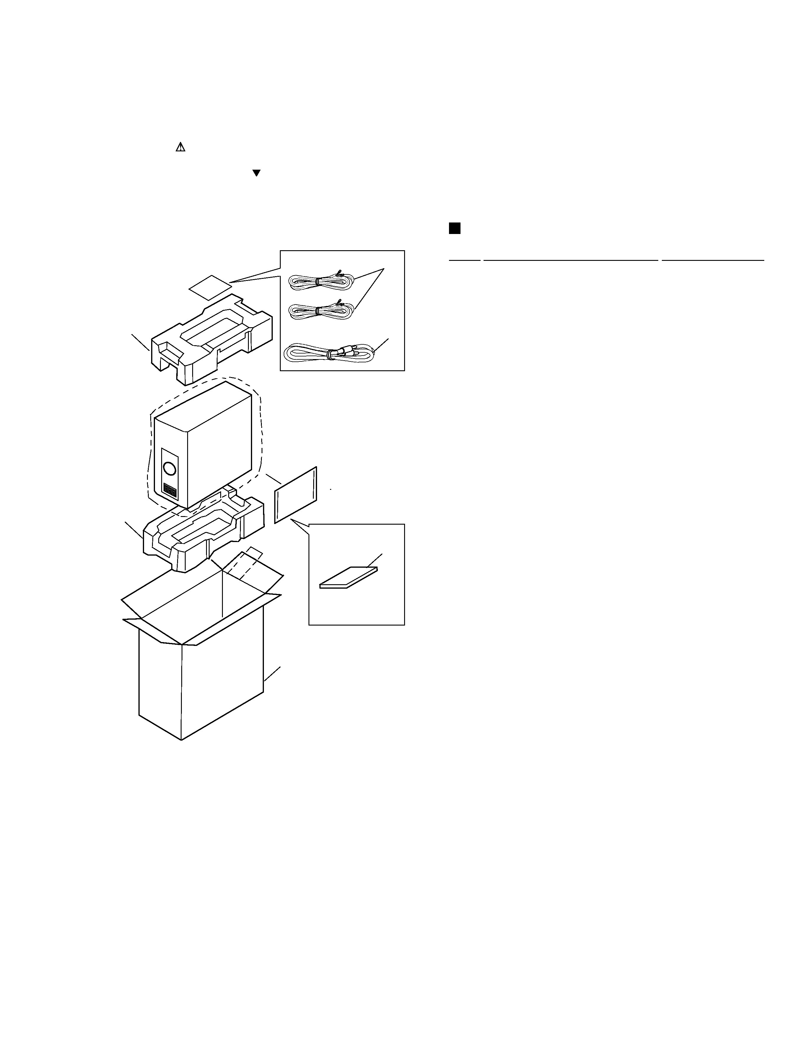
2.1 PACKING
3
4
3
1
2
5
1
Speaker Cord
305131
2
RCA Pin Cord
305232
3
Cushion
305239
4
Operating Instructions
310235
(English, Chinese)
5
Packing Case
310242
PACKING PARTS LIST
Mark No.
Description
Part No.
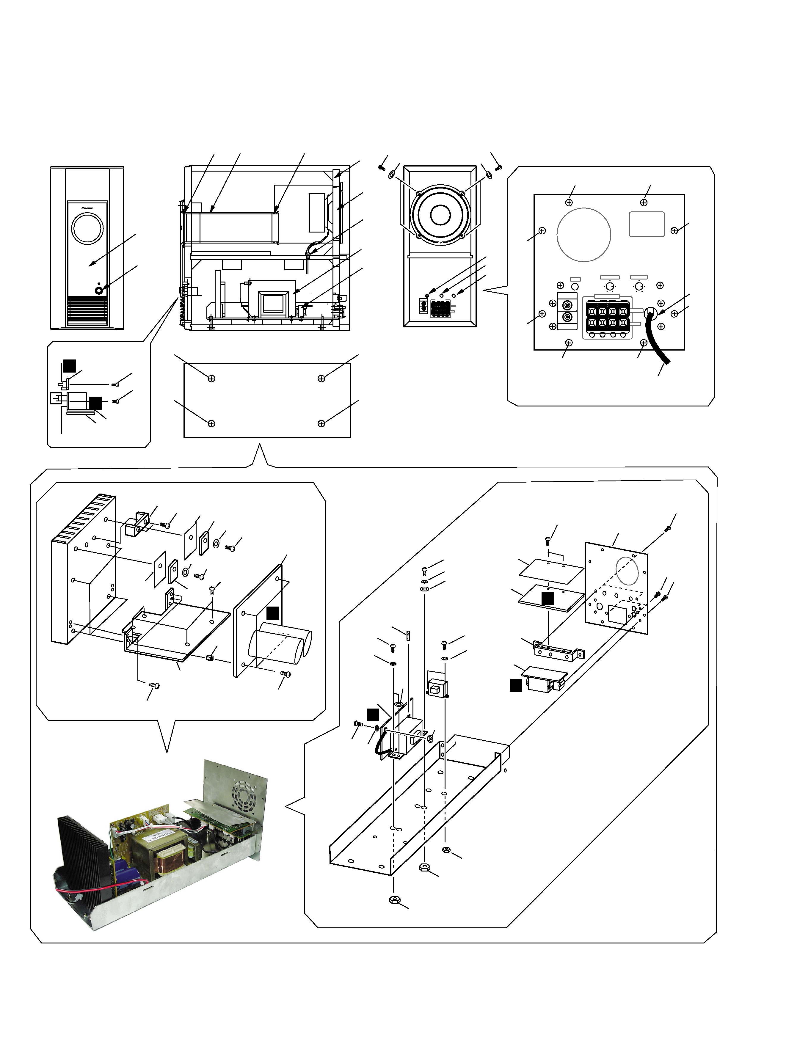
2. EXPLODED VIEWS AND PARTS LIST
NOTES:
· Parts marked by "NSP" are generally unavailable because they are not in our Master Spare Parts List.
· The mark found on some component parts indicates the importance of the safety factor of the part.
Therefore, when replacing, be sure to use parts of identical designation.
· Screws adjacent to mark on the product are used for disassembly.
4
S-W80S
2.2 EXTERIOR
STANDBY/
POWER ON
POWER
LINE LEVEL
OUTPUT
LINE LEVEL
INPUT
Hz
50
200
-
-
L
R
SPEAKER LEVEL
INPUT
OUTPUT
+
+
2
-
-
L
R
SPEAKER LEVEL
INPUT
OUTPUT
+
+
45
42 47
48
43
38
30
31
39
46
18
27
11
1
1
20
24
34
37
26
19
23
33
14
3
3
23
21
12
15
8
16
9
23 45
28
33
23
25
22
13
23
23
29
33
7
5
5
5
5
5
5
5
5
40
41
41
17
44
35
B
A
C
E
D
F
6
10
19
4
36
20
24
34
37
32
32
32
32
37
6
37
(Front)
(Side)
(Rear)
(Bottom)

5
S-W80S
Mark No.
Description
Part No.
1
Screw (PW SW,LED)
BBZ26P080FMC
2
Screw (HS Holder)
BBZ30P080FMC
3
Screw (Terminal,Jack,PCB Hold)
BBZ30P100FZB
4
Screw (GND Cord)
BMZ30P080FMC
5
Screw (Rear Panel)
BYC30P100FZK
6
Screw (Speaker)
BYC40P200FZB
7
HS Holder
E305002
8
PCB Holder
E305003
9
TS Holder
E305005
10
Rear Panel
E305006B
11
Insulation Sheet (PWS ASSY)
E305033
12
Shield Sheet (HEAD ASSY)
E305034
13
Spacer (Heat Sink)
E305518
14
Fuse (FU501 : 1.6A250V)
FSE1.6A250
15
HEAD ASSY
HEAD1002
16
INPUT ASSY
IN1002
17
Cord Bush (Power Cord)
KBUF41
18
LED ASSY
LED1002
19
Nut (GND Cord,Sub PWR. T.)
NB30FMC
20
Nut (Main PWR. T.)
NB40FMC
21
Screw (HEAD ASSY)
PBZ26P080FZK
22
Screw (POA ASSY)
PMZ30P060FMC
23
Screw (TR,TS,HS,Sub PWR. T.) PMZ30P100FMC
24
Screw (Main PWR. T.)
PMZ40P120FMC
25
POA ASSY
POA1002
26
POS ASSY
POS1002E
27
PWS ASSY
PWS1002
28
Transistor (Q111)
Q2SC51980
29
Transistor (Q112)
Q2SA19410
30
Power Transformer (T501)(Main) T0660
31
Power Transformer (T502)(Sub)
T1120
32
Screw (Network Assy)
TMZ40P300FZB
33
Washer (Tr,Sub PWR T.)
WC30FMC
34
Washer (Main PWR T.)
WC40FMC
35
AC Power Cord
WPPHP-205
36
Washer (GND Cord)
WS30FMC
37
Washer (Main PWR. T.)
WS40FMC
38
Speaker
305113
39
Power Switch Knob
305121
40
Phase Switch Knob
305122
41
Volume Knob
305123
42
Packing (Front Panel)
305212
43
Packing (Speaker)
305216
44
Cord Bush (SP Cord)
926209
45
TR Insulating Sheet
ZCW-4
46
Front Panel
305109
47
Paper Duct
305211
48
Duct Ring
305110
EXTERIOR PARTS LIST