ORDER NO.
PIONEER CORPORATION 4-1, Meguro 1-chome, Meguro-ku, Tokyo 153-8654, Japan
PIONEER ELECTRONICS (USA) INC. P.O. Box 1760, Long Beach, CA 90801-1760, U.S.A.
PIONEER EUROPE NV Haven 1087, Keetberglaan 1, 9120 Melsele, Belgium
PIONEER ELECTRONICS ASIACENTRE PTE. LTD. 253 Alexandra Road, #04-01, Singapore 159936
PIONEER CORPORATION 2006
RRV3385
T ZZS APR. 2006 Printed in Japan
SPEAKER SYSTEM
Subwoofer
S-W3700
XTW/UC
This service manual is intended for qualified service technicians; it is not meant for the casual do-it-
yourselfer. Qualified technicians have the necessary test equipment and tools, and have been trained to
properly and safely repair complex products such as those covered by this manual.
Improperly performed repairs can adversely affect the safety and reliability of the product and may void the
warranty. If you are not qualified to perform the repair of this product properly and safely, you should not risk
trying to do so and refer the repair to a qualified service technician.
WARNING
This product contains lead in solder and certain electrical parts contain chemicals which are known to the state of California to
cause cancer, birth defects or other reproductive harm.
Health & Safety Code Section 25249.6 Proposition 65
2
1
23
4
12
3
4
C
D
F
A
B
E
S-W3700
NSP
1
Subwoofer
SMW6208
NSP
2
Accessory Set
SME6087
Speaker Cord (SW: Purple)
SDS6041
Non Skid Pad (for Subwoofer) SEC2070
Polyethylene Bag S1
SHL1352
3
Operating Guide (English, French) SRD6062
NSP
Model Label
SAN6387
4
Protector
SHA6114
5
Protection Sheet
SHC1821
6
Packing Case
SHG6230
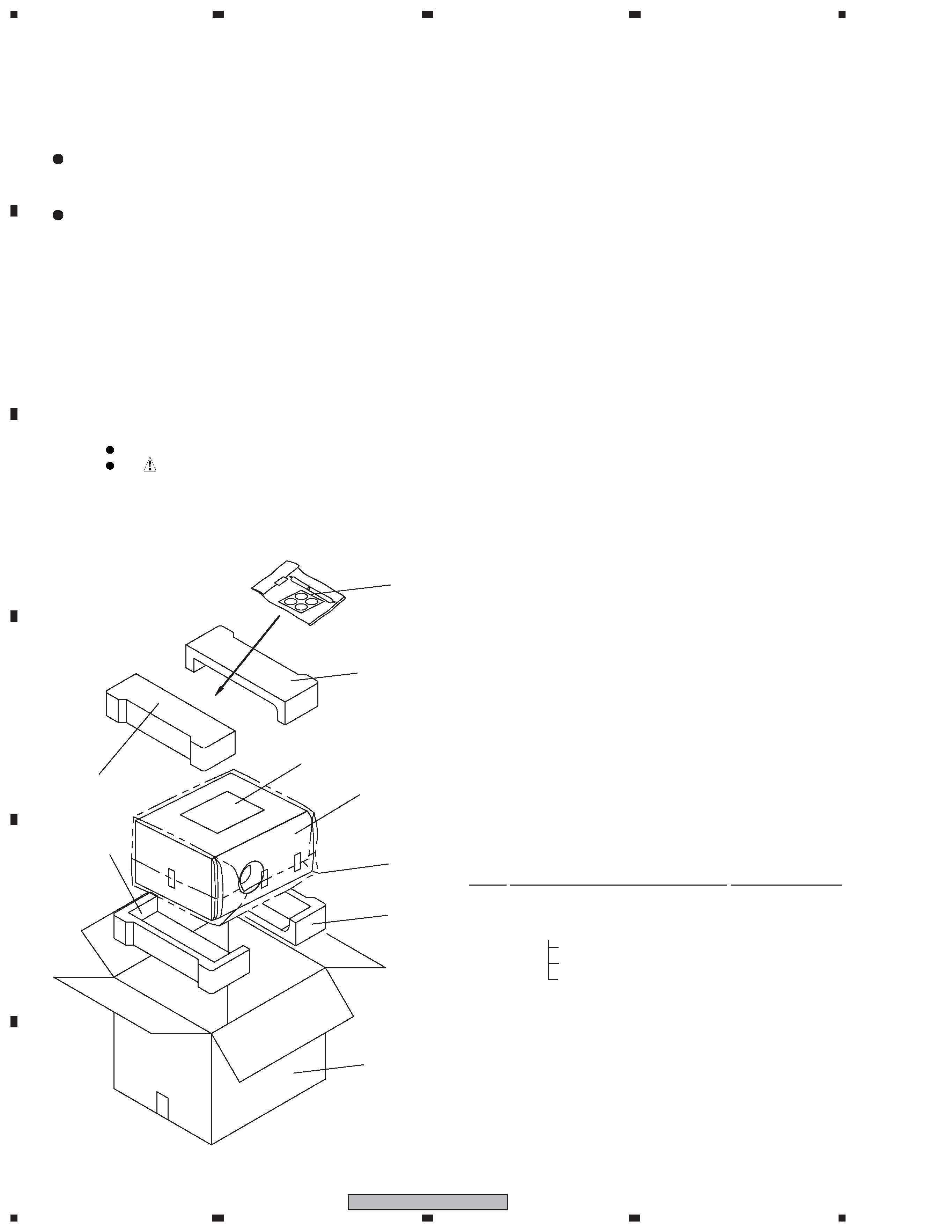
Parts marked by "NSP" are generally unavailable because they are not in our Master Spare Parts List.
The
mark found on some component parts indicates the importance of the safety factor of the part.
Therefore, when replacing, be sure to use parts of identical designation.
NOTES:
2. EXPLODED VIEWS AND PARTS LIST
Mark No.
Description
Part No.
2.1 PACKING
PACKING Parts List
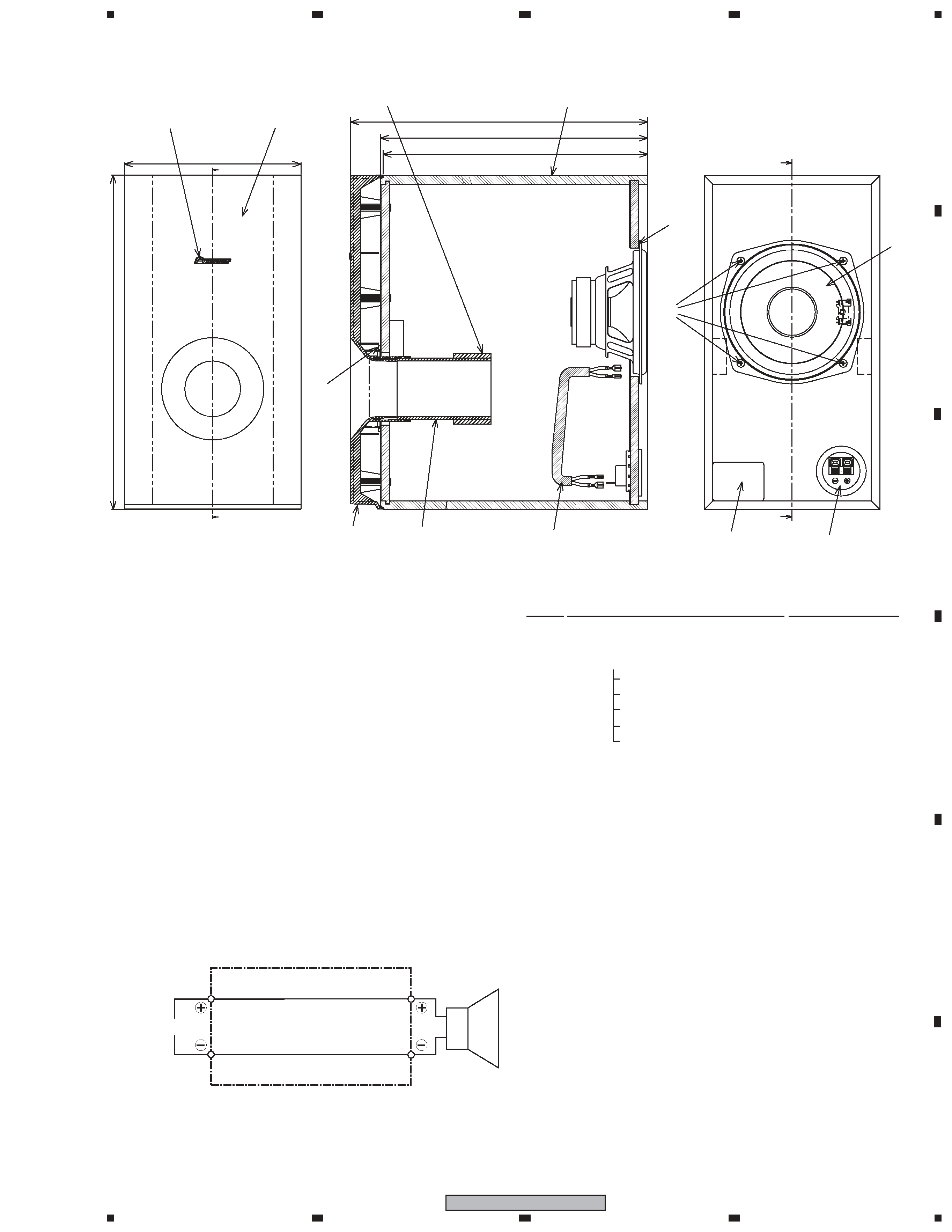
1. FOR PRECAUTION OF REASSEMBLY AND DISASSEMBLY
SUBWOOFER
The speaker unit is attached to the back board by 4 external
screws. To detach it, unfasten those screws. When attaching it,
face its terminal rightward.
The cosmetic baffle assy is attached to the baffle board by
press-fitting. To detach it, pry it open by inserting a flat blade
screwdriver into lower slot.
4 (2/2)
6
5
2
4 (2/2)
4 (1/2)
4 (1/2)
1
3
3
1
23
4
1
2
3
4
C
D
F
A
B
E
S-W3700
SUBWOOFER Parts List
2.2 SUBWOOFER
NSP
1
Cabinet
SMM6045
2
Cosmetic BF. Assy
SXB6006
NSP
3
Badge 37
SAM1507
4
Packing
SEC2072
NSP
5
Paper Tube 60
SMR6011
NSP
6
Acoustic Absorbent
SMV2229
NSP
7
Cosmetic Baffle
SNK2927
8
Connecting Cord
SDD6017
9
Input Terminal
SKX1060
10
Gasket
SEC6058
11
Speaker
A14LU75-52F
12
Screw (for Speaker)
BYC40P130FTB
Mark No.
Description
Part No.
3. SCHEMATIC DIAGRAM
INPUT
Speaker
Black
Red
Connecting Cord (SDD6017)
12
11
320
288
(285)
1
2
4
3
5
6
8
9
7
Model Label
190
360
10