
ORDER NO.
PIONEER CORPORATION 4-1, Meguro 1-chome, Meguro-ku, Tokyo 153-8654, Japan
PIONEER ELECTRONICS (USA) INC. P.O. Box 1760, Long Beach, CA 90801-1760, U.S.A.
PIONEER EUROPE NV Haven 1087, Keetberglaan 1, 9120 Melsele, Belgium
PIONEER ELECTRONICS ASIACENTRE PTE. LTD. 253 Alexandra Road, #04-01, Singapore 159936
PIONEER CORPORATION 2007
S-LX70-LR
RRV3697
SPEAKER SYSTEM
S-LX70-LR
XTW/E
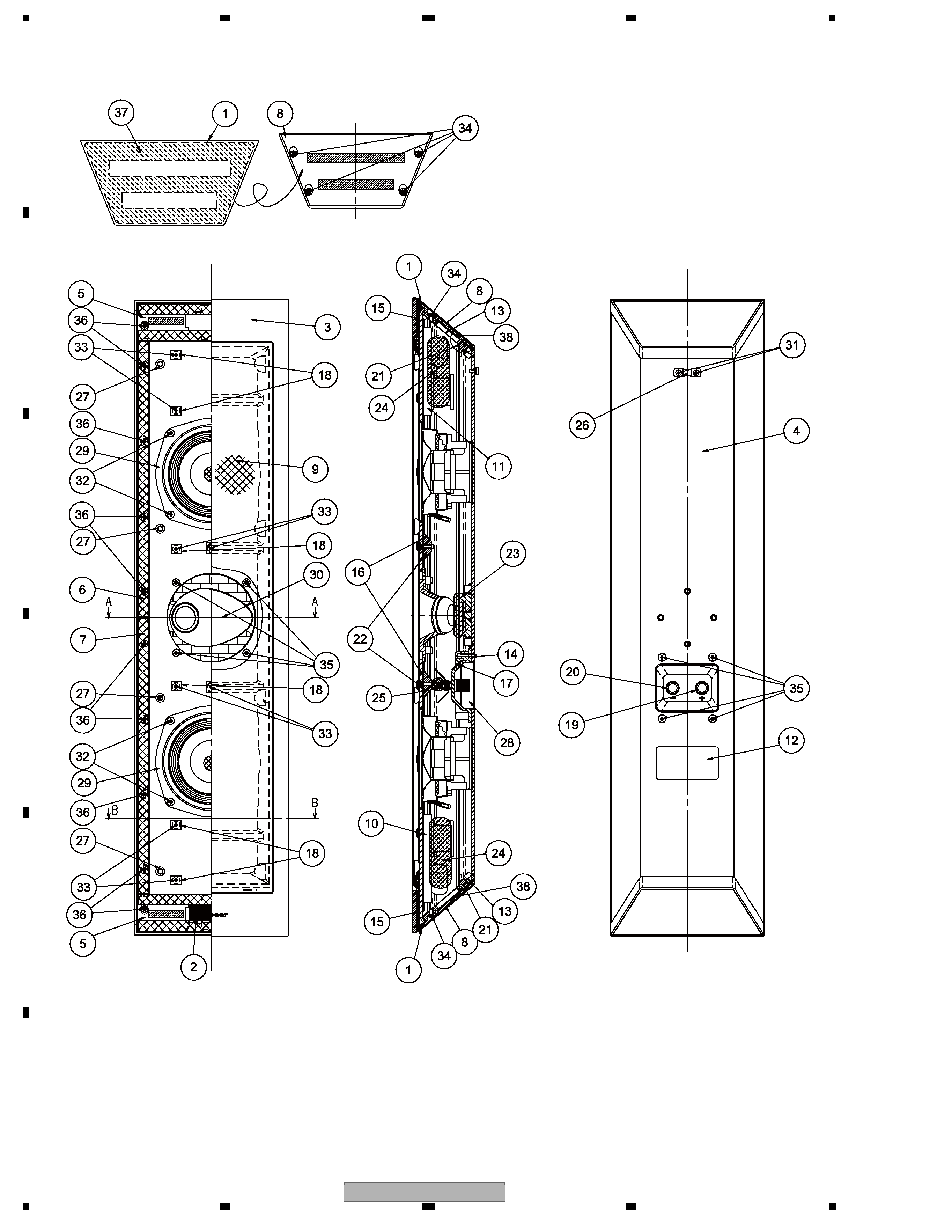
1. REASSEMBLY AND DISASSEMBLY PRECAUTIONS
1.1 GRILLE
· The grille is attached to the cabinet with catches and adhesive.
To remove the grille, use a thin, rigid object, such as a flathead
screwdriver or metal ruler, to pry it off, being careful not to
damage its acrylic coating. To reattach the grille, apply adhesive to
the catches and then press the grille firmly to the cabinet.
1.2 WOOFER
· Each woofer is attached to the cabinet with 4 screws accessible
from the outside. To remove the woofer, remove these screws. To
reassemble, make sure that the terminal plate of the speaker unit
faces to the lower .
1.3 TWEETER
1. Remove the upper woofer.
2. Remove the packing (SEC2186) between the upper woofer and
the tweeter.
Note: As packing cannot be reused, procure new packing (SEC2186)
for reassembly.
3. Remove the 3 screws. Then pass your hand through the hole for
the woofer and pull out the reinforcing plate.
4. Remove the 4 screws from the tweeter, then pull the tweeter out
through the hole for the woofer. To reinstall the tweeter, place it
so that its terminal plate faces to the upper. Reattach the tweeter
so that the opening of the horn faces left-side and right-side.
The part numbers of the tweeter for L ch and R ch are different.
Be careful in the tweeter installation.
The opening of the horn face becomes the reverse direction
when it attaches a tweeter for L ch and R ch in reverse.
1.4 NETWORK ASSY
1. The Network Assy for the tweeter is located at the upper of upper
woofer, and the Network Assy for the woofer is located at the
lower of the lower woofer.
2. As the screws are covered by packing, before removing the
Network Assy remove the packing first, then remove the woofer.
As packing cannot be reused, procure new packing (SEC2186)
for reassembly.
3. Each Network Assy is attached to the inside of the cabinet with 4
screws accessible from the outside.
4. Pass your hand through the hole for the woofer and securely hold
the Network Assy in place while removing the 4 screws. Pull the
Network Assy out through the hole for the woofer.
T-ZZR NOV. 2007 Printed in Japan
S-LX70-LR
2
12
3
4
12
3
4
C
D
F
A
B
E
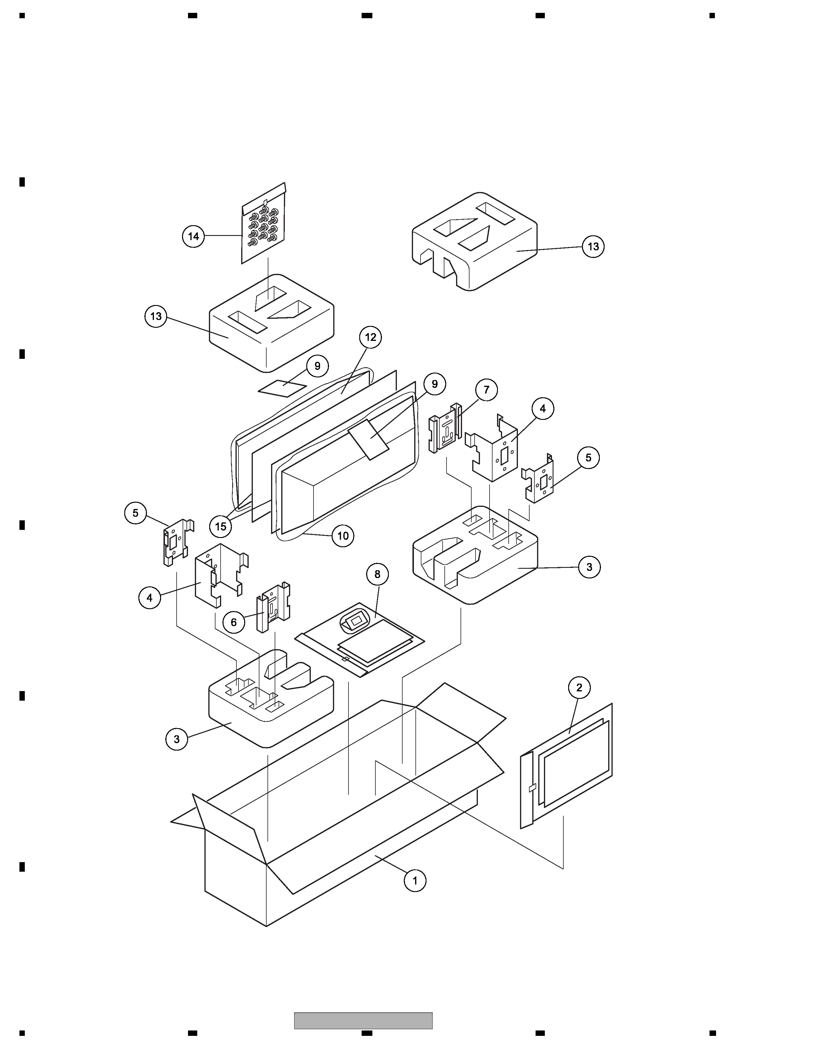
2. EXPLODED VIEWS AND PARTS LIST
2.1 PACKING
NOTES :
· Parts marked by " NSP " are generally unavailable because they are not in our Master Spare Parts List.
· The
> mark found on some component parts indicates the importance of the safety factor of the part.
Therefore, when replacing, be sure to use parts of identical designation.

S-LX70-LR
3
56
7
8
56
7
8
C
D
F
A
B
E
PACKING Parts List
Mark No.
Description
Part No.
1
Packing Case
SHG2801
NSP 2
1..Template Set
SME3834
2..Poly Bag S2
SHL1440
2..Wall Mounting Template
SRK1030
2..Wall Mounting Template
SRK1034
3
Bottom Protector
SHA2590
NSP 4
1..Bracket Set
SME3797
2..Poly Bag S1
SHL1371
2..Bracket
SNA1489
NSP 5
1..Bracket Set
SME3796
2..Poly Bag S1
SHL1414
2..Bracket
SNA1488
NSP 6
1..Bracket Set
SME3810
2..Poly Bag S1
SHL1371
2..Bracket
SNA1490
NSP 7
1..Bracket Set
SME3824
2..Poly Bag S1
SHL1371
2..Bracket
SNA1492
NSP 8
1..Accessories Set
SME3833
2..Cleaning Cloth
SER1358
2..Poly Bag S2
SHL1265
2..Operating Instructions
SRD1347
(English, French, Spanish, Chinese)
NSP 9
Caution Label
SRR1025
10
Protection Sheet
SHC1862
11
. . . . .
12
. . . . .
13
Top Protector
SHA2589
NSP 14
1..Screw Set
SME3809
2..Screw
BMZ40P080FTB
2..Screw
BMZ50P120FTB
2..Poly Bag S0
SHL1412
15
Protection Sheet
SHB1181
S-LX70-LR
4
12
3
4
12
3
4
C
D
F
A
B
E
2.2 SPEAKER SYSTEM
Rch is symmetrical to center line.
Speaker (L:GDE25-51D-L, R:GDE25-51D-R)exc.
*This product appearance shows Lch.
Red
Black

S-LX70-LR
5
56
7
8
56
7
8
C
D
F
A
B
E
SPEAKER SYSTEM Parts List
Mark No.
Description
Part No.
NSP 1
Aluminum Panel
SAH1172
NSP 2
Aluminum Plate
SAH1173
NSP 3
Cosmetic Panel
SLD1021
NSP 4
1..Cabinet
SNH1088
2..Fung Nut M5
SBN1074
NSP 5
Sticking Board (A)
SNK2992
NSP 6
Sticking Board (B)
SNK2993
NSP 7
Sticking Board (C)
SNK2994
NSP 8
Top & Bottom Plate
SNK2998
9
1..Grille
SMG1892
NSP
2..Grille Cloth
SAS1624
NSP
2..Gasket
SEC2175
2..Damper
SER1366
NSP
2..Grille Frame
SMH1129
10
Network Assy (Woofer)
SWN1790
11
Network Assy (Tweeter)
SWN1791
NSP 12
Model Label (FL)
SAN4005
NSP 12
Model Label (FR)
SAN4006
NSP 13
Gasket
SEC2130
14
Gasket
SEC2132
NSP 15
Gasket
SEC2133
16
Gasket
SEC2176
17
Packing
SEC2184
18
Packing
SEC2186
19
Input Terminal (Red)
SKX1103
20
Input Terminal (Black)
SKX1104
NSP 21
MDF Bar
SLX1165
22
Reinforce Board
SLX1170
NSP 23
Acoustic Absorbent
SMV2255
NSP 24
Acoustic Absorbent
SMV2244
NSP 25
Acoustic Absorbent
SMV2257
26
Fastener
SNB1073
27
Catch
SNK3031
28
Input Terminal Case
SNK2996
29
Speaker (Woofer)
A13GU40-52H
30
Speaker (Tweeter)(L)
GDE25-52D-L
30
Speaker (Tweeter)(R)
GDE25-52D-R
31
Screw
BMZ35P050FBN
32
Screw
BMZ40P060FTB
33
Screw
CKC40P160FTB
34
Screw
CMZ40P200FTC
35
Screw
CPZ40P100FBN
36
Screw
PMZ40P060FTC
37
Tape
SEH1129
38
Packing
SEC2188