ORDER NO.
PIONEER CORPORATION 4-1, Meguro 1-chome, Meguro-ku, Tokyo 153-8654, Japan
PIONEER ELECTRONICS SERVICE, INC. P.O. Box 1760, Long Beach, CA 90801-1760, U.S.A.
PIONEER EUROPE NV Haven 1087, Keetberglaan 1, 9120 Melsele, Belgium
PIONEER ELECTRONICS ASIACENTRE PTE. LTD. 253 Alexandra Road, #04-01, Singapore 159936
PIONEER CORPORATION 2001
c
S-L11-Q-LRW
RRV2484
T ZZV JUNE 2001 Printed in Japan
SPEAKER SYSTEM
XJI/EW
65S
This service manual is intended for qualified service technicians; it is not meant
for the casual do-it-yourselfer. Qualified technicians have the necessary test
equipment and tools, and have been trained to properly and safely repair complex
products such as those covered by this manual.
Improperly performed repairs can adversely affect the safety and reliability
of the product and may void the warranty. If you are not qualified to perform the
repair of this product properly and safely, you should not risk trying to do so and
refer the repair to a qualified service technician.
WARNING
This product contains lead in solder and certain electrical parts contain chemicals
which are known to the state of California to cause cancer, birth defects or other
reproductive harm.
Health & Safety Code Section 25249.6 Proposition 65
This product is component of system.
Component
System
Service Manual
Remarks
COMPACT MINI COMPONENT
SEREO CD TUNER
XC-L11
RRV2470
STEREO POWER AMPLIFIER
M-L11
RRV2479
SPEAKER SYSTEM
S-L11-Q-LRW
RRV2484
This service manual
FOR PRECAUTION OF
REASSEMBLY AND DISASSEMBLY
The grille is attached to the cabinet by 4 external screws.
To detatch it ,unfasten those screws.
(Satellite)
The cosmetic baffle is attached to the baffle by press-fitting.
To detatch it , pry it open by inserting a flat blade screwdriver
into lower side.
To attach the cosmetic baffle, replace it on the backboard cor-
rectly by press-fitting.
The input terminal is attached to the backboard by press-fitting.
To detatch it , pry it open by inserting a flat blade screwdriver
into lower side.
To attach the input terminal, replace it on the backboard cor-
rectly by press-fitting. (The red terminal is right side.)
The woofer is attatched to the backboard by 4 external screws.
To detach it, unfasten those screws. When attatching it, face its
terminal downward.
(Subwoofer)
The speaker element is attatched to the baffle by 4 internal
screws. To detach it, first remove the cabinet . Then remove the
speaker element by unfastening those screws. When attatching
it, face its terminal upward.
SATELLITE
SUBWOOFER
S-L11-Q-LRW
2
Mark No.
Description
Part No.
SCHEMATIC DIAGRAM
For Packing
Parts marked by "NSP" are generally unavailable because they are not in our Master Spare Parts List.
The
mark found on some component parts indicates the importance of the safety factor of the part.
Therefore, when replacing, be sure to use parts of identical designation.
NOTES:
PARTS LIST
Mark No.
Description
Part No.
NSP
Satellite Speaker
SMW1661
NSP
Subwoofer
SMW1662
NSP
Accessary Set
SEA1561
Speaker Wire (for Subwoofer)
SDF1091
Speaker Wire (for Satellite)
SDS1065
Non Skid Pad
SEC1537
Stand
SET1041
NSP
Polyethylene Bag
SHL1223
Top Protector
SHA2310
Middle Protector
SHA2311
Bottom Protector
SHA2312
Packing Case
SHG2338
NSP
Polyethylene Bag (for Subwoofer)
SHL1212
Polyethylene Bag S2 (for Satellite) SHL1291
Satellite Speaker
Speaker
D87DU61-53F
Screw (for Speaker)
BPZ40P060FZK
Screw (for Cabinet)
BPZ40P120FZK
Screw (for Sidewood)
BYC35P160FNI
Fin-Lok M5 (for Stand attaching) SBN1049
Speaker Cord
SDD1303
Packing (for Cabinet)
SEC1532
NSP
Packing (for Cabinet)
SNK2541
Damper (for Cabinet, Grille)
SEP1237
Input Terminal
KKX1015
Grille
SMG1723
NSP
Badge23
SAM1487
NSP
Grille Cloth
SAS1497
NSP
Grille Frame
SMH1030
NSP
Sidewood R
SMS1440
NSP
Sidewood L
SMS1441
NSP
Acoustic Absorbent
SMV2090
(for upper back side)
NSP
Acoustic Absorbent
SMV2091
(for lower back side)
NSP
Cabinet
SNK2536
NSP
Stamped Model Label
SME3150
NSP
Label Back
SAN2942
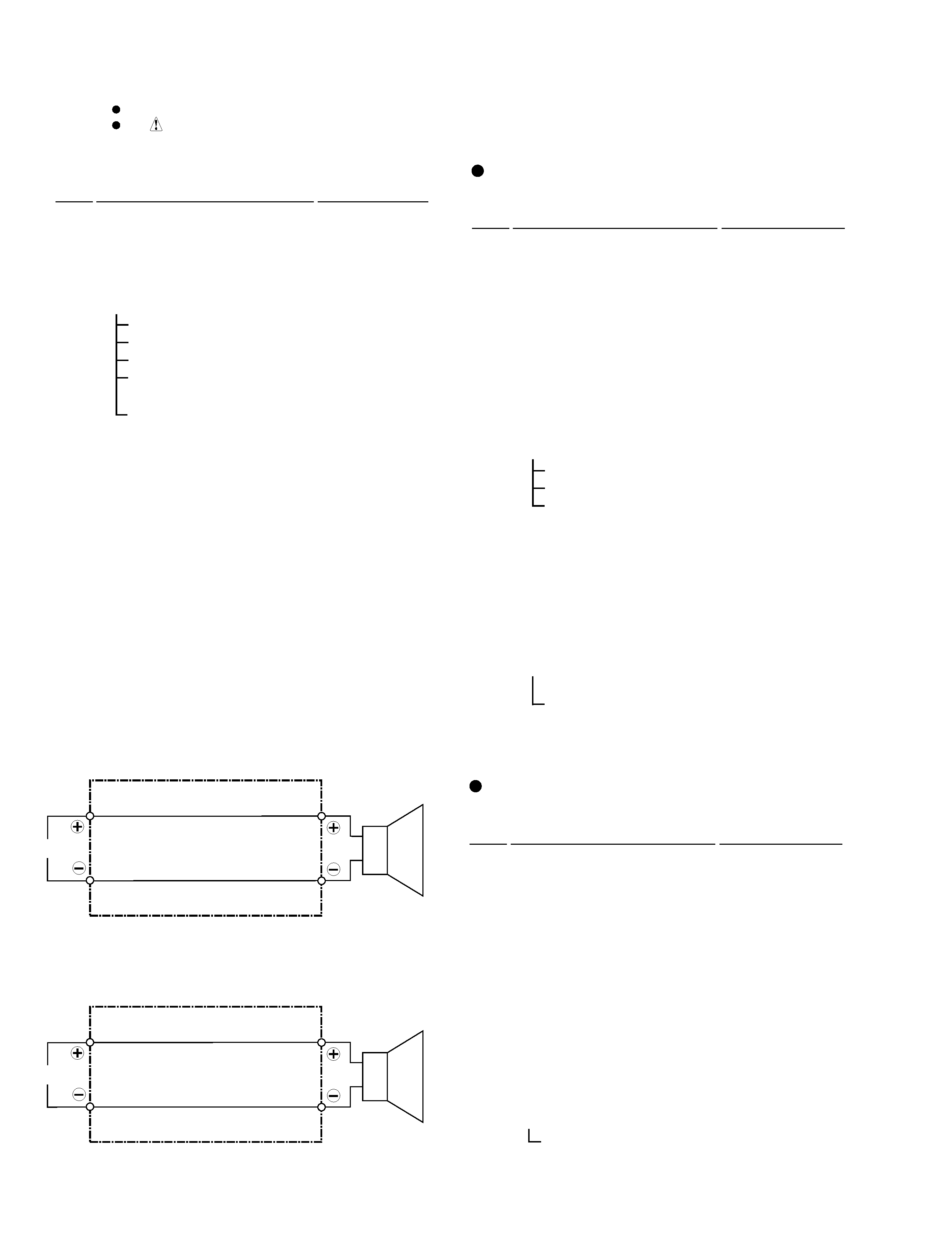
INPUT
RED
WHITE
Full-Range
Speaker Cord (SDD1303)
INPUT
RED
BLACK
Woofer
Speaker Cord (SDD1304)
PARTS LIST
PARTS LIST
Satellite
Mark No.
Description
Part No.
Sub Woofer
Speaker
A14ER75-52C
Screw (for Speaker)
BYC40P160FZB
Speaker Cord
SDD1304
NSP
Packing (for Cosmetic Baffle)
SEC1567
NSP
Paper Tube 50
SMR1340
Input Terminal
KKX1014
Non Skid Pads
SEC1534
NSP
Acoustic Absorbent
SMV1955
(for bottom side)
NSP
Acoustic Absorbent
SMV2003
(for upper front side)
NSP
Cabinet
SMM1941
NSP
Cosmetic Baffle
SNK2532
NSP
Stamped Model Label
SME3152
NSP
Label Back
SAN2944
PARTS LIST
Subwoofer
S-L11-Q-LRW
3
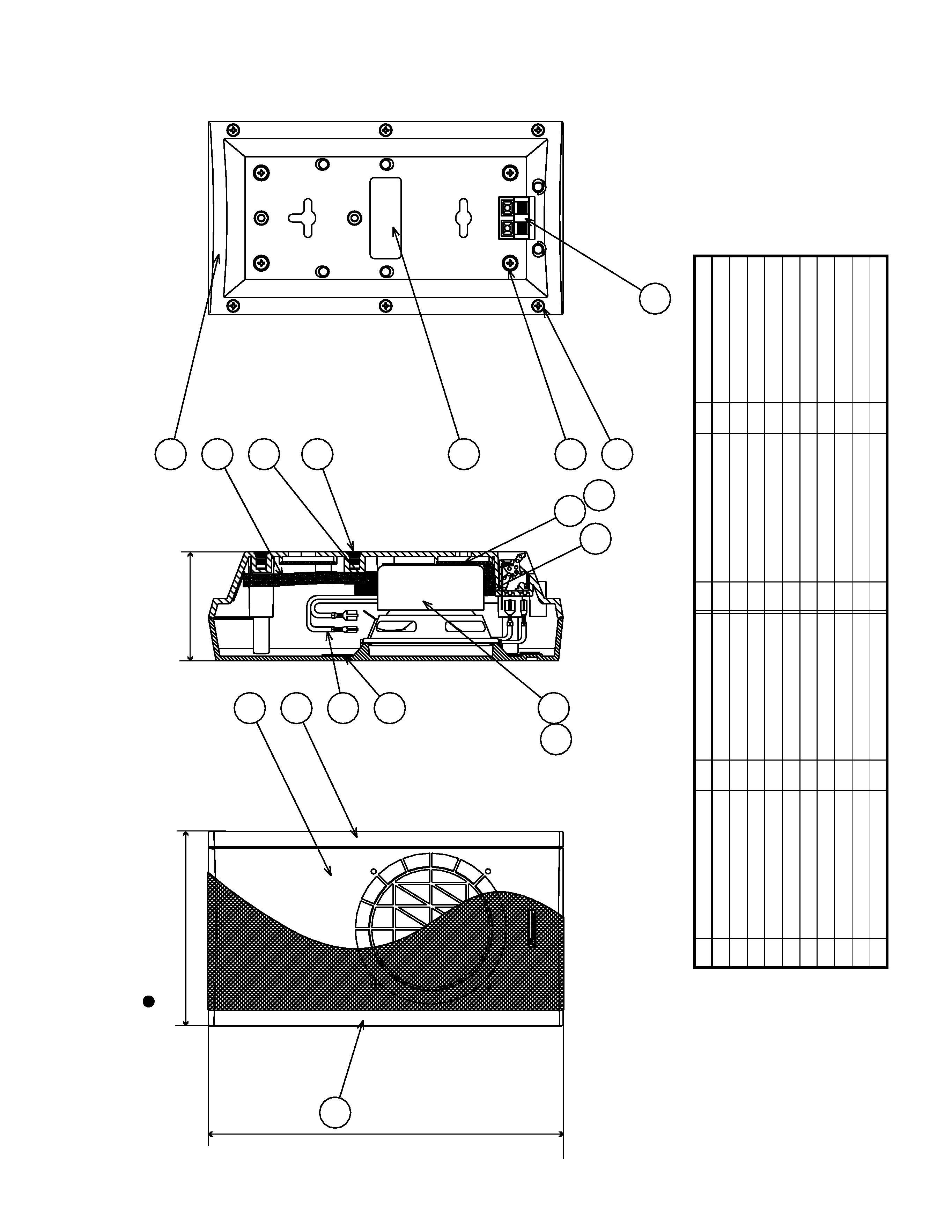
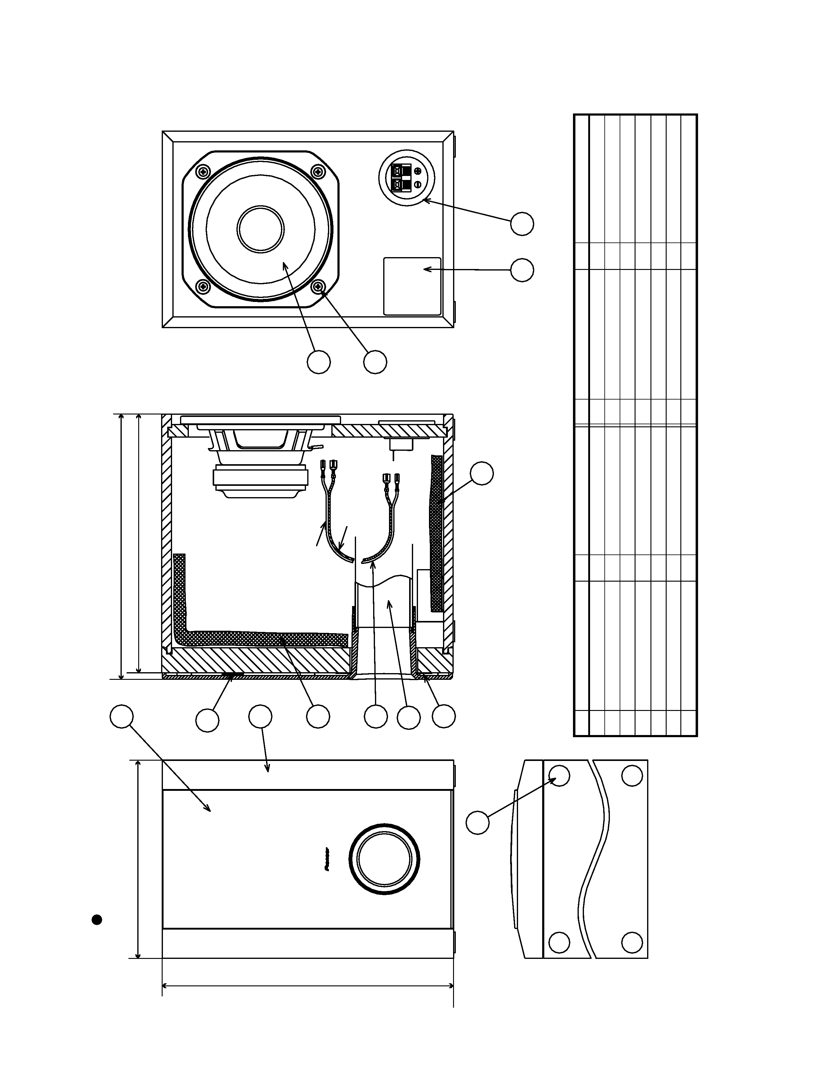
PRODUCT APPEARANCE
No.
1
2
3
4
5
6
9
7
8
1
1
1
1
1
1
1
1
Cabinet
BPZ40P060FZK
BPZ40P120FZK
BYC35P160FNI
SMV2090
SNK2541
Grille
Sidewood
R
Speaker
Sidewood
L
Speaker
Cord
Input
Terminal
Acoustic
Absorbent
2
Fin-Lok
M5
10
2
Packing
Screw
Screw
Screw
Label
Back
4
4
6
1
SEP1237
SEC1532
Damper
2
11
12
13
14
15
16
SEP1237
Damper
1
Packing
1
SMV2091
Acoustic
Absorbent
1
17
18
Num
Part
name
Remarks
No.
Num
Part
name
Remarks
17
11
18
10
12
13
14
15
16
5
6
3
2
1
8
9
7
4
(125)
(228)
(70)
Satellite
Speaker
S-L11-Q-LRW
4
No.
1
2
3
4
5
6
1
1
1
1
1
1
Cabinet
SMV1955
SMV2003
Speaker
Cosmetic
Baffle
Acoustic
Absorbent
Acoustic
Absorbent
Input
Terminal
Speaker
Cord
Paper
Tube
50
Label
Back
Non
Skid
Pad
1
1
1
4
SEC1567
SEC1568
BYC40P160FZB
Packing
Screw
1
4
7
8
9
10
11
12
Packing
2
13
Num
Part
name
Remarks
No.
Num
Part
name
Remarks
12
11
10
6
9
2
4
3
1
13
5
7
8
(190.5)
(255)
(248.8)
(281)
Black
Red
for
Wf
(+)
Red
(
)Black
for
Input
Terminal
(+)
Red
(
)Black
Sub
Woofer