ORDER NO.
PIONEER ELECTRONIC CORPORATION 4-1, Meguro 1-Chome, Meguro-ku, Tokyo 153-8654, Japan
PIONEER ELECTRONICS SERVICE, INC. P.O. Box 1760, Long Beach, CA 90801-1760, U.S.A.
PIONEER ELECTRONIC (EUROPE) N.V. Haven 1087, Keetberglaan 1, 9120 Melsele, Belgium
PIONEER ELECTRONICS ASIACENTRE PTE. LTD. 253 Alexandra Road, #04-01, Singapore 159936
PIONEER ELECTRONIC CORPORATION 1999
RRV2141
T-ZZM MAY 1999 Printed in Japan
FOR PRECAUTION OF
REASSEMBLY AND DISASSEMBLY
This product is component of systems.
SPEAKER SYSTEM
S-IS21
XJI/E
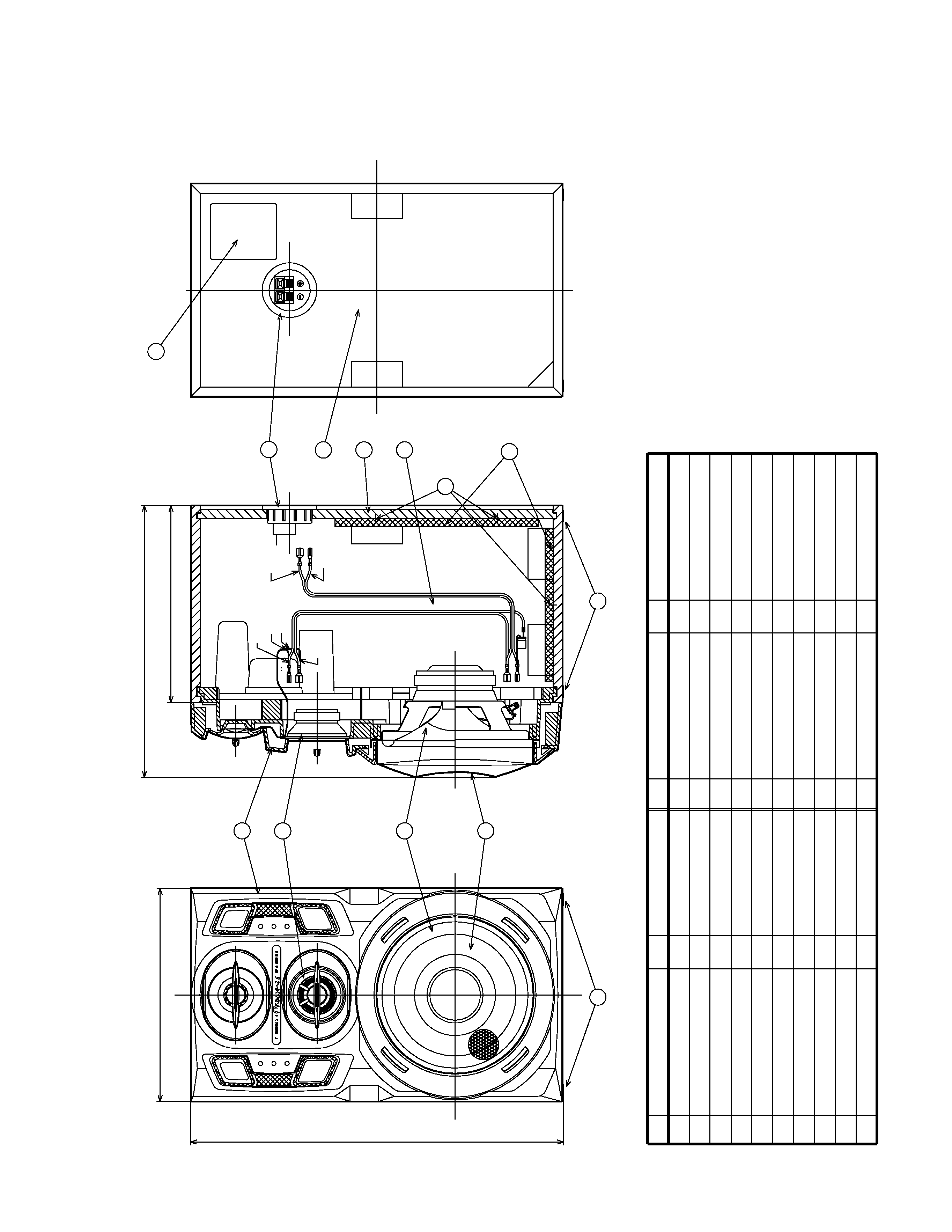
The cosmetic baffle is attached to the baffle by its bosses and
press-fitting.
To detach it, pry it open by inserting a flat blade screwdriver
into the cosmetic baffle lower side.
Be careful not to damage the cosmetic baffle and cabinet in
this case.
IS-21T
XC-IS21T
M-IS21
S-IS21
System
Service Manual
Remarks
RRV2148
RRV2149
RRV2143
RRV2141
Component
IS-21MD
XC-IS21MD
M-IS21
S-IS21
CD TUNER DECK
CD MD TUNER
STEREO POWER AMPLIFIER
SPEAKER SYSTEM
This service manual
65S
This service manual is intended for qualified service technicians; it is not meant
for the casual do-it-yourselfer. Qualified technicians have the necessary test
equipment and tools, and have been trained to properly and safely repair complex
products such as those covered by this manual.
Improperly performed repairs can adversely affect the safety and reliability
of the product and may void the warranty. If you are not qualified to perform the
repair of this product properly and safely, you should not risk trying to do so and
refer the repair to a qualified service technician.
WARNING
This product contains lead in solder and certain electrical parts contain chemicals
which are known to the state of California to cause cancer, birth defects or other
reproductive harm.
Health & Safety Code Section 25249.6 Proposition 65
The woofer is attached to the baffle by 4 external screws.
To detach it, first remove the cosmetic baffle.
Next unfasten those screws.
Then remove the woofer.
When attaching it, face its terminal downward.
The midrange is attached to the baffle by 2 external screws.
To detach it, first remove the cosmetic baffle.
Next unfasten those screws.
Then remove the midrange.
When attaching it, face its terminal upward.
The tweeter is attached to the baffle by inserting.
To detach it, first remove the cosmetic baffle.
Next pull it off the baffle.
Then remove the tweeter.
When attaching it, insert the tweeter in the baffle.
2
S-IS21
NSP
Cabinet
SMM1853
NSP
Inner Baffle
SNK2398
Network ASSY
SWN1604
Input Terminal
KKX1014
NSP
Acoustic Absorbent
SMV1886
NSP
Punching Net
SNC1174
Cosmetic Baffle ASSY
SXB1372
NSP
Cosmetic Baffle
SNK2399
NSP
Cosmetic Ring
SNK2400
Speaker (Woofer)
A16LC83-52D
Speaker (Mid-range)
FD66AP45-55D
Screw (for Woofer)
BPZ40P120FMC
NSP
Stamped Model Label
SME2923
NSP
Model Label
SAN2712
Speaker Cord
SDS1064
Non-Skid Pads
SEC1374
Top Protector
SHA2170
Bottom Protector
SHA2171
NSP
Poly Bag
SHL1212
Packing Case
SHG2206
Mark No.
Description
Part No.
For Packing
Parts marked by "NSP" are generally unavailable because they are not in our Master Spare Parts List.
The
mark found on some component parts indicates the importance of the safety factor of the part.
Therefore, when replacing, be sure to use parts of identical designation.
NOTES:
PARTS LIST
Mark No.
Description
Part No.
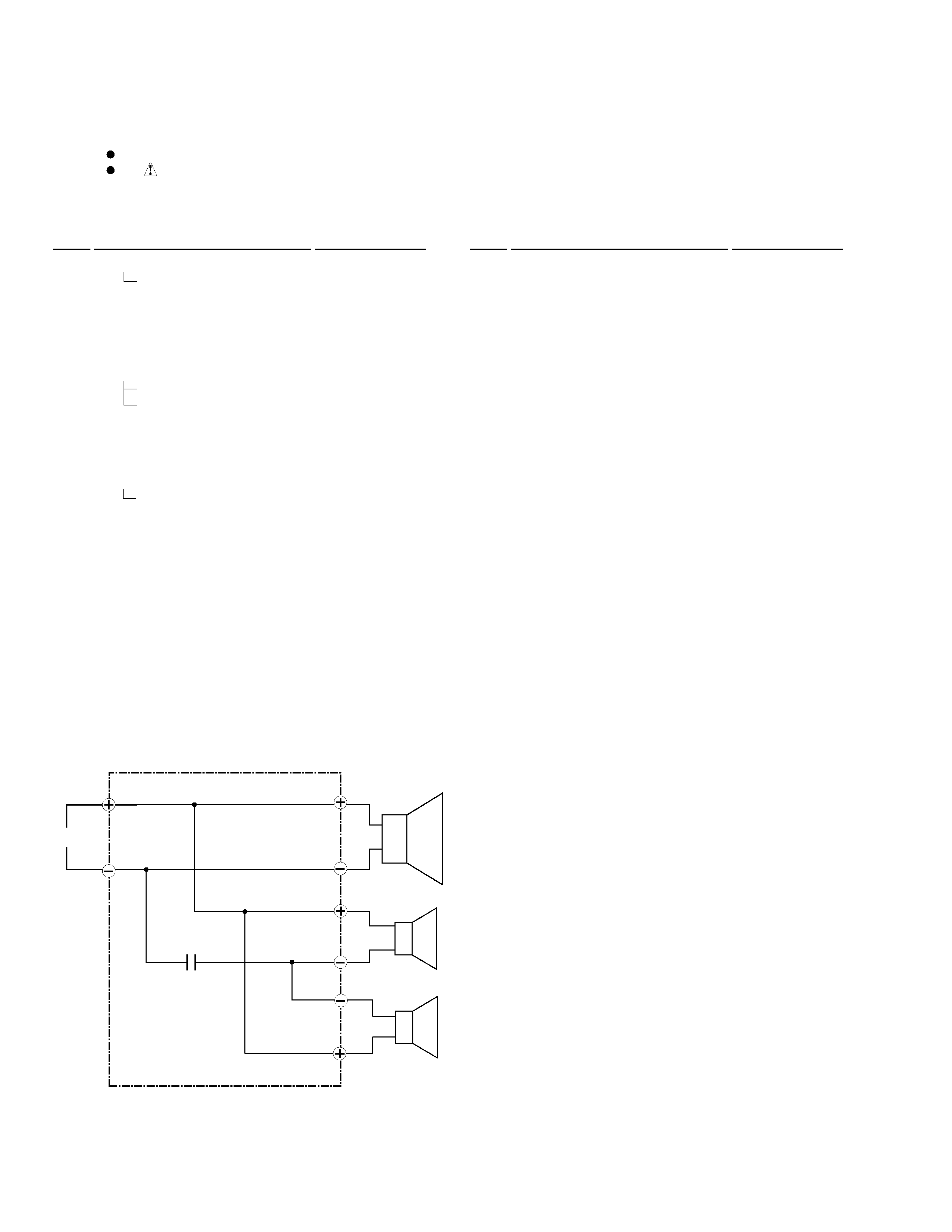
Network ASSY (SWN1604)
SCHEMATIC DIAGRAM
Woofer
Mid-range
I NPUT
Tweeter
1.5
µF/63V
Blue
White
Red
Black
Red
White
White
Blue
3
S-IS21
8
9
12
10
1
Screw
BPZ40P120FMC
6
11
Acoustic
Absorbent
72
4
1
Non
Skid
Pad
Model
Label
Cosmetic
Baffle
Assy
Input
Terminal
Punching
Net
Staple
Cabinet
Speaker
Speaker
4
1
1
1
1
1
6
5
4
3
2
1
Part
name
Num.
No.
Remarks
Part
name
Num.
No.
Remarks
1
Network
Assy
KKX1014
210
367.5
8
2
1
3
4
5
6
9
9
10
7
12
10
194
(267.6)
BLUE
WHITE
RED
WHITE
BLACK
RED
PRODUCT APPEARANCE