ORDER NO.
PIONEER CORPORATION 4-1, Meguro 1-chome, Meguro-ku, Tokyo 153-8654, Japan
PIONEER ELECTRONICS (USA) INC. P.O. Box 1760, Long Beach, CA 90801-1760, U.S.A.
PIONEER EUROPE NV Haven 1087, Keetberglaan 1, 9120 Melsele, Belgium
PIONEER ELECTRONICS ASIACENTRE PTE. LTD. 253 Alexandra Road, #04-01, Singapore 159936
PIONEER CORPORATION 2005
RRV3238
T ZZK AUG. 2005 Printed in Japan
FOR PRECAUTION OF
REASSEMBLY AND DISASSEMBLY
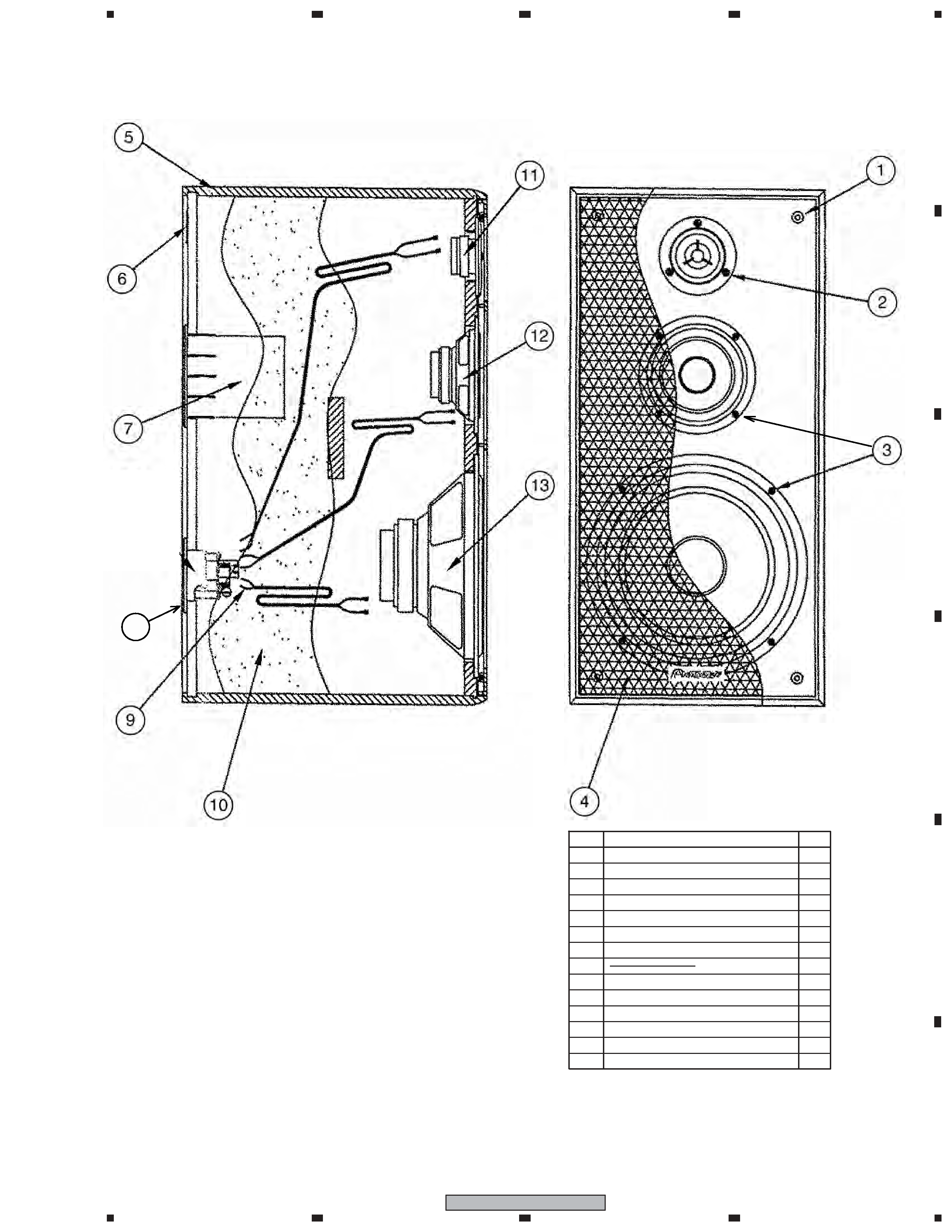
The grille is attached to the cabinet by catches. Detach by pull-
ing it toward you.
The woofer is attached to the baffle by 4 external screws. To
detach it, first remove the grille. Then unfasten those screws.
When attaching it, face its terminal downward.
The mid-range is attached to the baffle by 4 external screws. To
detach it, first remove the grille. Then unfasten those screws.
When attaching it, face its terminal upward.
The tweeter is attached to the baffle by 3 external screws. When
attach it with the plus terminal on the right and the minus termi-
nal on the left.
The Network Assy is attached to the rear board by 4 external
screws. To detach it, first remove the Woofer, Mid-Range and
Tweeter. Then unfasten those screws. When attaching it, face
its plus terminal rightward.
SPEAKER SYSTEM
S-HF41-LR
XTW/UC
65S
This service manual is intended for qualified service technicians; it is not meant for the
casual do-it-yourselfer. Qualified technicians have the necessary test equipment and
tools, and have been trained to properly and safely repair complex products such as
those covered by this manual.
Improperly performed repairs can adversely affect the safety and reliability
of the product and may void the warranty. If you are not qualified to perform the repair
of this product properly and safely, you should not risk trying to do so and refer the
repair to a qualified service technician.
WARNING
This product contains lead in solder and certain electrical parts contain chemicals
which are known to the state of California to cause cancer, birth defects or other
reproductive harm.
Health & Safety Code Section 25249.6 Proposition 65
2
1
23
4
12
3
4
C
D
F
A
B
E
S-HF41-LR
Parts marked by "NSP" are generally unavailable because they are not in our Master Spare Parts List.
The
mark found on some component parts indicates the importance of the safety factor of the part.
Therefore, when replacing, be sure to use parts of identical designation.
NOTES:
PARTS LIST
Speaker System
4
2
3
Speaker System
3
1
1
1
1
SCHEMATIC DIAGRAM
1
Protector
SHA2531
2
Packing Case
SHG2694
3
Polyethylene Bag
SHL1449
4
Operating Instructions
SRD1305
(English, French)
Network Assy
SWN1767
Grille
SMG1860
Speaker (Tweeter)
SWD9006
Speaker (Woofer)
SWB9001
Speaker (Mid-Range)
SWM9022
Screw (for Tweeter)
BYC30P180FZB
Screw (for Woofer, Mid)
BYC40P200FZB
Screw (for Input Terminal)
BYC35P180FZB
For Packing
Mark No.
Description
Part No.
Speaker System
Mark No.
Description
Part No.
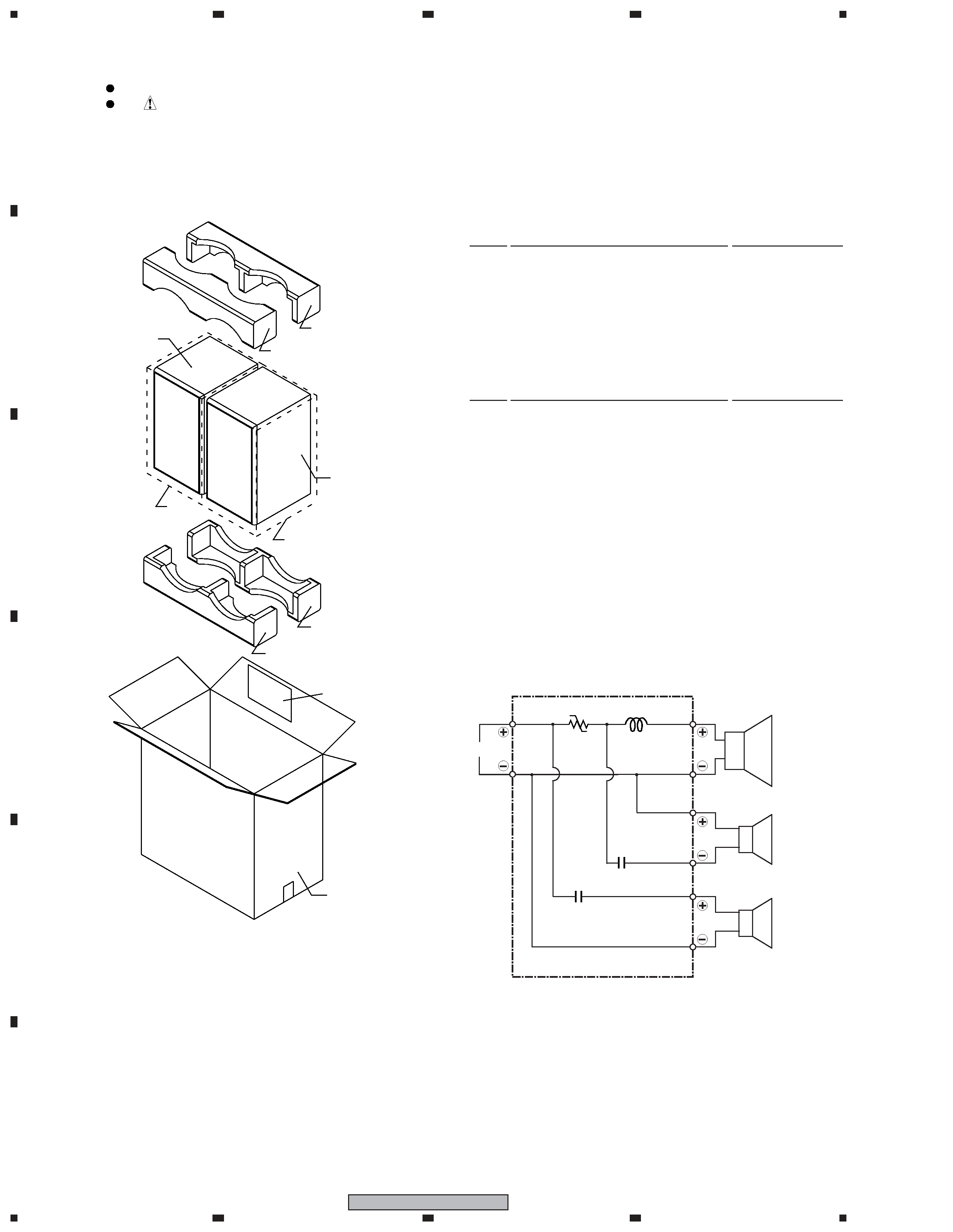
Network Assy (SWN1767)
L
1.2 mH
T60/160
P.SW
1.5
µF/50V
C
12
µF/50V
C
INPUT
Woofer
Blue
White
Black
Blue
Tweeter
Black
Red
Mid-Range
P.SW
P.SW has extreme positive resistance-temperature characteristics. (Less than 0.3W at
the normal temperature). If an abnormal current flows to P.SW due to an excessive
input or unusual signal, P.SW heats up and the resistance rapidly increases. With this
function, the speakers are protected from excessive input or unusual signal. The
resistance value increases even when using a soldering iron for repairing, so allow it to
cool before using.
3
1
23
4
1
2
3
4
C
D
F
A
B
E
S-HF41-LR
PRODUCT APPEARANCE
1
1
1
1
1
1
4
12
1
Screw
11
3
8
1
10
1
4
Part Name
No.
Num.
9
8
7
6
5
4
3
2
1
Catch
Screw
Grille
Cabinet
Model Label
Duct
Network Assy
Acoustic Absorbent
Tweeter
Mid-Range
13
14
Woofer
Screw
14