
1
CS-G405-K/Q
Service
Manual
ORDER NO.
PET99011
PIONEER CORPORATION 4-1, Meguro 1-Chome, Meguro-ku, Tokyo 153-8654, Japan
PIONEER ELECTRONICS SERVICE, INC. P.O. Box 1760, Long Beach, CA 90801-1760, U.S.A.
PIONEER ELECTRONIC (EUROPE) N.V. Haven 1087, Keetberglaan 1 B-9120 Melsele, Belgium
PIONEER ELECTRONICS ASIACENTRE PTE. LTD. 501 Orchard Road, #10-00, Wheelock Place, Singapore 238880
©PIONEER CORPORATION 1999
1999 Printed in U.S.A.
·
The front grille is attached to the cabinet by catches. Detach it by
pulling toward you.
·
The side grille is attached to the cabinet by its bosses. To detach it,
pry it open by inserting a flat blade screwdriver into side. To attach
it, press it to the baffle.
·
The woofer is attached to the side board by external screws. To
detach it, unfasten those screws. When attaching, face its terminal
downward.
·
The midrange is attached to the baffle by external screws. To
detach it, unfasten those screws. When attaching, face its terminal
downward.
·
The tweeter, together with the trim-ring, is attached to the baffle by
external screws. To detach it, unfasten those screws. When
attaching, face its terminal downward.
HOW TO REASSEMBLE AND
DISASSEMBLE
65S
This service manual is intended for qualified service technicians; it is
not meant for the casual do-it- your selfer. Qualified technicians have
the necessary test equipment and tools, and have been trained to
properly and safely repair complex products such as those covered by
this manual.
Improperly performed repairs can adversely affect the safety and
reliability of the product and may void the warranty. If you are not
qualified to perform the repair of this product properly and safely, you
should not risk trying to do so and refer the repair to a qualified service
technician.
SPEAKER SYSTEM
S-H351F-K
2
CS-G405-K/Q
PARTS LIST
NOTES: · Parts marked by "NSP" are generally unavailable because they are not in our Master Spare Parts List.
· The "
"mark found on some component parts indicates the importance of the safety factor of the part.
Therefore, when replacing, be sure to use parts of identical designation.
Mark No. Description
Parts No.
Mark No. Description
Parts No.
For Packing
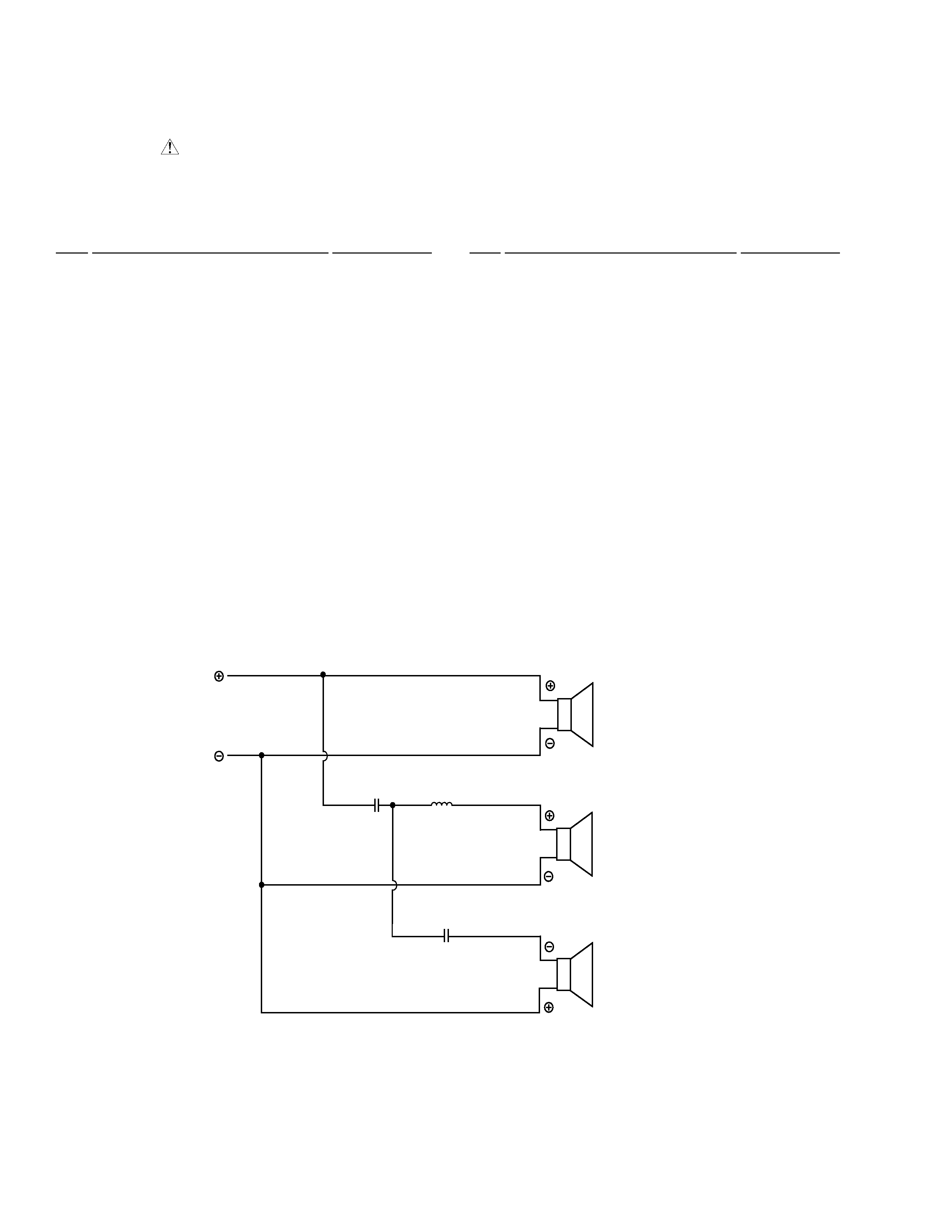
SCHEMATIC DIAGRAM
S-H351F-K
Low Frequency Transducer
25-35A/XL
Packing Case
268320
Mid Frequency Transducer
237301
Corner Pad Assy Top
237232
High Frequency Transducer
237316
Corner Pad Assy Bottom
237247
Front Grille Assembly
268340
Poly Bag
162905
Grille Assembly for Low Frequency Trans
268439
Catch
122898
Plastic Port Tube
230102
Crossover Assembly
237445
Screw (for Trans)
222011
Instruction Manual
268335
Speaker Wire
101717
INPUT
RED
BLACK
6.8
µ F / 50 V
GREEN
WHITE
TWEETER
WHITE
BLUE
WOOFER
RED
WHITE
MID RANGE
4.7
µ F / 50 V
0.23 mH