ORDER NO.
PIONEER CORPORATION 4-1, Meguro 1-chome, Meguro-ku, Tokyo 153-8654, Japan
PIONEER ELECTRONICS (USA) INC. P.O. Box 1760, Long Beach, CA 90801-1760, U.S.A.
PIONEER EUROPE NV Haven 1087, Keetberglaan 1, 9120 Melsele, Belgium
PIONEER ELECTRONICS ASIACENTRE PTE. LTD. 253 Alexandra Road, #04-01, Singapore 159936
PIONEER CORPORATION 2005
RRV3263
T-ZZS NOV. 2005 Printed in Japan
S-FL1
Flat Panel Speaker
XTW/E5
S-FL1
2
1
23
4
12
3
4
C
D
F
A
B
E
S-FL1
Protector Set
Protector Set
Protector Set
Stic
ks
The line that
shows a position
Fixes using tapes.
1
4
1
6
8
7
5
2
3
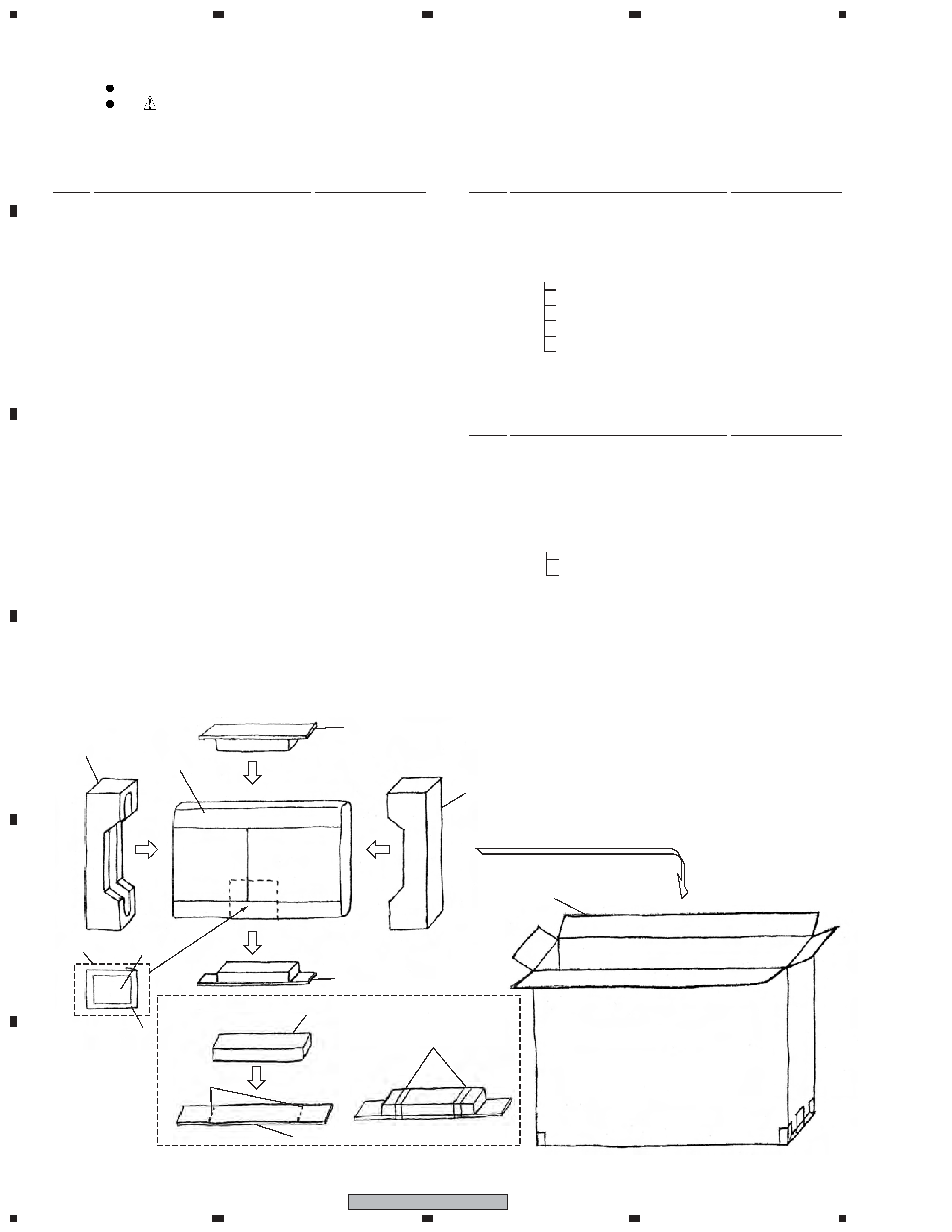
Packing
Speaker Assy
SMW1901
NSP
External Frame A
SLH1087
NSP
External Frame B
SLH1088
NSP
External Frame C
SLH1089
NSP
External Frame D
SLH1090
NSP
Frame Brace
SNE1032
Coner Protector A
SNK2833
Coner Protector B
SNK2834
Punching Net
SNC1205
NSP
Model Label
SAN3543
NSP
Serial Label
SAX1420
Insulating Tube
SDM1007
Packing A
SEC2007
Packing B
SEC2008
Packing
SEC2067
Suspension C
SEP1347
Input Terminal Base
SNK2835
Cap
SNK2836
Handle
SNK2837
NSP
Wiring Label
SRW1113
Screw (for Frame Brace)
BMZ40P080FTC
Screw (for Input Terninal)
OPZ30P100FTB
Screw (for Input Terminal Base)
PMZ30P250FTC
Screw (for Handle)
PMZ40P100FTB
Screw (for External Frame)
PMZ40P350FTC
Screw (for Coner Protector)
SKC50H350FTB
Screw (for Punching Net)
SMZ40H060FTB
Screw (for Cap)
SMZ60H200FTB
Input Terminal Ass'y
SKX1099
NSP
Cord D
SDB1157
NSP
Cord E
SDB1158
Insulating Tube
SDM1007
NSP
Insulating Tube
SDM1008
NSP
Input Terninal
SKN1010
1 Protector
SHA2511
2 PS Spacer
SHA2527
3 Protector
SHB1171
4 Protection Sheet
SHC1833
5 Packing Case
SHG2705
NSP
6 Accessories Set
SME3691
7
Polyethylene Bag S2
SHL1420
8
Operating Instructions
SRD1290
(English, French, German,
Italian, Spanish, Dutch, Chinese)
Parts marked by "NSP" are generally unavailable because they are not in our Master Spare Parts List.
The
mark found on some component parts indicates the importance of the safety factor of the part.
Therefore, when replacing, be sure to use parts of identical designation.
NOTES:
1. PARTS LIST
Mark No.
Description
Part No.
CS ASSY
For Packing
Mark No.
Description
Part No.
Mark No.
Description
Part No.
3
1
23
4
1
2
3
4
C
D
F
A
B
E
S-FL1
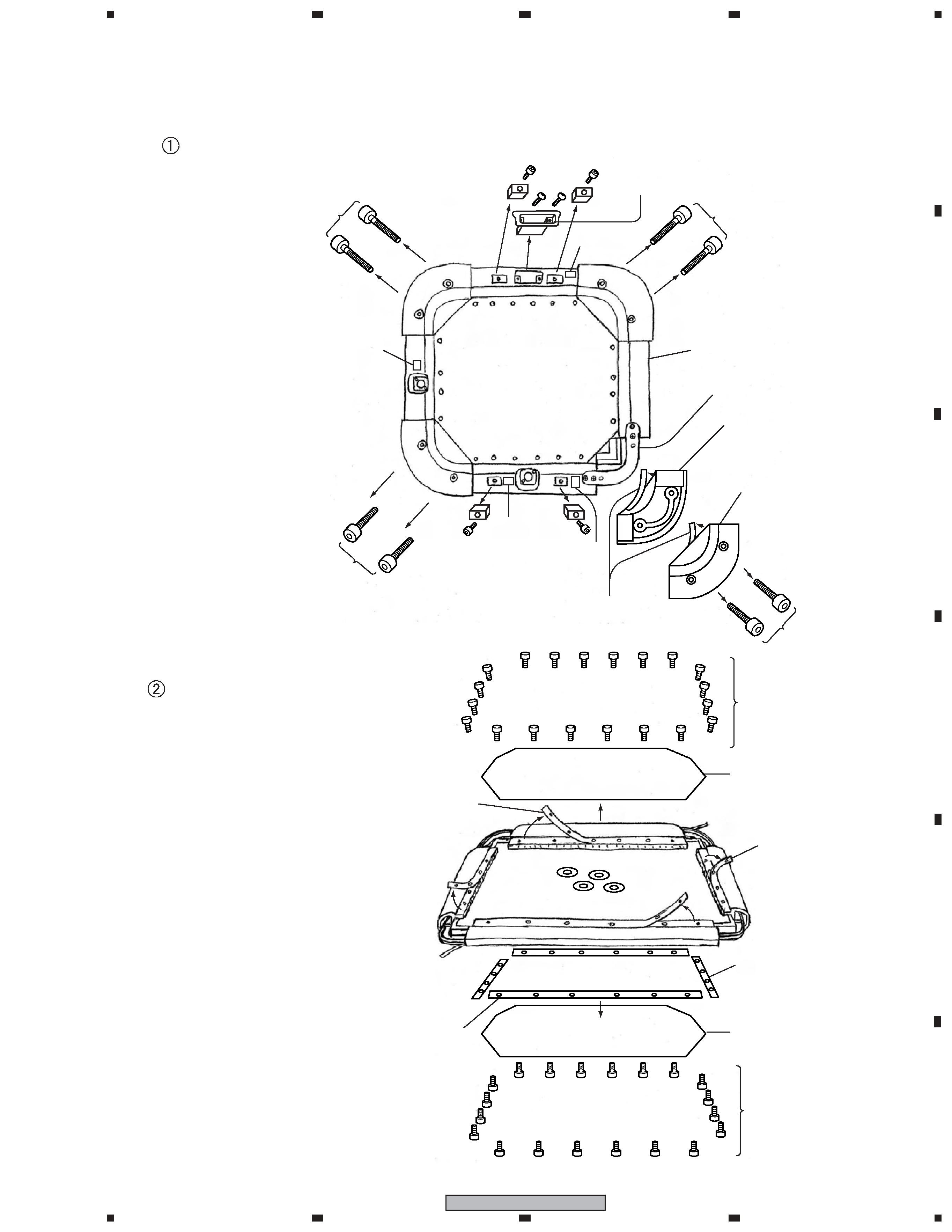
Detach the Coner Protector A,B
and Cap
Speaker System
Frame Brace (NSP)
Coner Protector A : 4pcs.
(SNK2833)
Coner Protector B : 4pcs.
(SNK2834)
Wiring Label
Wiring Label
Model Label
Cap x 4pcs.
(SNK2836)
Screw(SMZ60H200FTB) x 4pcs.
Screw
(SKC50H350FTB)
x 2pcs.
Screw
(SKC50H350FTB)
x 2pcs.
Screw
(SKC50H350FTB)
x 2pcs.
Screw
(SKC50H350FTB)
x 2pcs.
Handle(SNK2837)
Screw(PMZ40P100FTB) x 2pcs.
Serial
Label
2-1. DISASSEMBLY
< Back Side >
Packing (SEC2067)
x8pcs.
Detach the Punching Net
Punching Net
(SNC1205)
Punching Net
(SNC1205)
Packing A (Short)x 2pcs.
(SEC2007)
Packing A (Short)x 2pcs.
(SEC2007)
Packing B (Long)x 2pcs.
(SEC2008)
Packing B (Long)x 2pcs.
(SEC2008)
< Front Side >
Screw
(SMZ40H060FTB)
x 20pcs.
Screw
(SMZ40H060FTB)
x 20pcs.
2. FOR PRECAUTION OF DISASSEMBLY AND REASSEMBLY
4
1
23
4
12
3
4
C
D
F
A
B
E
S-FL1
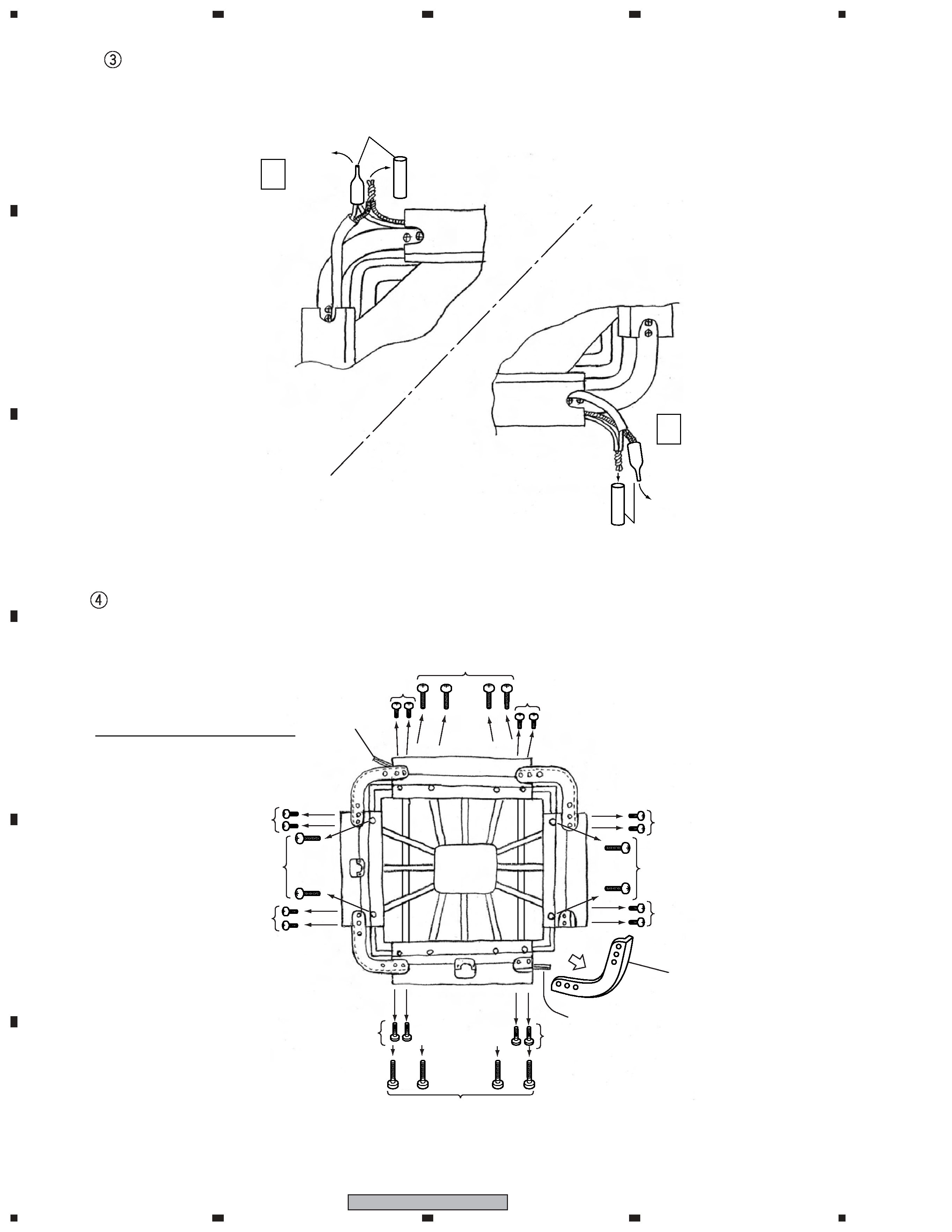
Cord
Cord
Screw for
External Frame
(PMZ40P350FTC)
Screw for External Frame
(PMZ40P350FTC) x 12pcs.
Screw for
External Frame
(PMZ40P350FTC)
Screw for
External Frame
(PMZ40P350FTC)
Turns over the speaker.
< Back side >
Screw for Frame Brace
(BMZ40P080FTC)
Screw for Frame Brace
(BMZ40P080FTC)
Frame Brace (NSP)
x 4pcs.
Be careful of direction.
Screw for Frame Brace
(BMZ40P080FTC)
Screw for Frame Brace
(BMZ40P080FTC)
Screw for Frame Brace
(BMZ40P080FTC)
Screw for Frame Brace
(BMZ40P080FTC)
Screw for Frame Brace (BMZ40P080FTC) x 16pcs.
Screw for Frame Brace (BMZ40P080FTC)
Unfasten the Screw for the External Frame and Detach the Frame Brace
Disconnect the Input Terminal Assy Cords and Speaker Assy Cords
A
B
Insulating Tube (SDM1007)
Insulating Tube
(SDM1007)
5
1
23
4
1
2
3
4
C
D
F
A
B
E
S-FL1
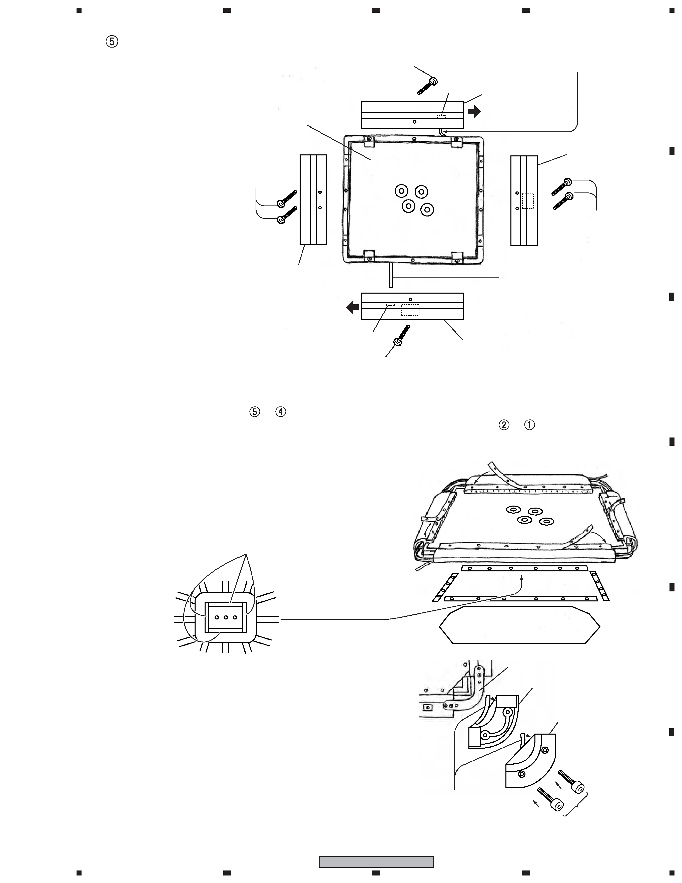
Reassembles by the order of
->
-> Connecting the Input Terminal Assy cord and
the Speaker Assy cord, Puts the Insulation Tube, Styling the connection cord ->
->
.
Note 1)
When you attach the Extenal Frame A, B, C, D to the speaker at first,
don't tighten the screw strongly.
But when you attach the Frame brace, fasten the screws strongly.
Note 2)
Stick the Suspension C
Stucks the suspension C on the center of the
frame back side, as shown in a figure.
Note 3)
Attach the Corner Protector
Sticks the Packing to the Corner Protector.
Covers the Frame Brace by the corner protector
and fasten the Screws.
Note 4) Attach the Punching Net
The Punching Net have distinction of the front and
the back side. The side which has burr arround the
hole is the back side. Be sure to attach it to inside.
2-2. REASSEMBLY
Frame Brace
Corner Protector A x4pcs.
(SNK2833)
Corner Protector B x4pcs.
(SNK2834)
2pcs. in each
every corner
(SKC50H350FTB)
Packing (SEC2067) x8pcs.
(Sticks on the illustration part
of the corner protector inner side.)
Suspension C (SEP1347)
< Front side >
Detach the External Frame
Speaker Assy
(SMW1901)
Hole
External Frame B
(NSP)
Draw out the cord from
the hole of External Frame B.
Draw out the cord from
the hole of External Frame D.
External Frame C
(NSP)
Screw for
External Frame
(PMZ40P350FTC)
External Frame D (NSP)
Hole
External Frame A
(NSP)
Screw for External Frame
(PMZ40P350FTC)
The direction that the
speaker cord comes.
The direction that the
speaker cord comes.
Screw for External Frame
(PMZ40P350FTC)
< Front Side >
Screw for External Frame
(PMZ40P350FTC) x 6pcs.