S-FCRW210-K
S-FCRW710-K
1
PIONEER CORPORATION
4-1, Meguro 1-Chome, Meguro-ku, Tokyo 153-8655, Japan
PIONEER ELECTRONICS SERVICE, INC.
P.O. Box 1760, Long Beach, CA 90801-1760, U.S.A.
© PIONEER CORPORATION 2001
CONTENTS
1. SAFETY INFORMATION ............................................. 2
2. DISASSEMBLY ............................................................ 3
3. PACKING, EXPLODED VIEWS AND PARTS LIST ..... 3
4. SCHEMATIC AND PCB CONNECTION DIAGRAMS .. 6
5. PCB CONNECTION DIAGRAM ................................. 10
6. PCB PARTS LIST ...................................................... 13
7. ADJUSTMENT ........................................................... 15
8. PANEL FACILITIES .................................................... 16
9. SPECIFICATIONS ....................................................... 17
Service
Manual
ORDER NO.
PET01007
HOME THEATER LOUDSPEAKER SYSTEM
S-FCRW210-K
S-FCRW710-K
L
E
D
O
M
E
P
Y
T
S
T
E
N
O
P
M
O
C
R
E
W
O
P
T
N
E
M
E
R
I
U
Q
E
R
K
R
A
M
E
R
C
X
U
KC
X
C
K
R
E
F
O
O
W
B
U
S
R
E
T
N
E
C
T
N
O
R
F
E
T
I
L
L
E
T
A
S
R
A
E
R
E
T
I
L
L
E
T
A
S
K
-
0
1
2
W
R
C
F
-
S1
3
2
V
0
2
1
C
A
K
-
0
1
7
W
R
C
F
-
S1
3
3
V
0
2
1
C
A
THIS MANUAL IS APPLICABLE TO THE FOLLOWING MODELS AND TYPES
S-FCRW210-K
S-FCRW710-K
2
1. SAFETY INFORMATION
This service manual is intended for qualified service technicians ; it is not meant for the casual do-it-yourselfer. Qualified technicians
have the necessary test equipment and tools, and have been trained to properly and safely repair complex products such as those
covered by this manual.
Improperly performed repairs can adversely affect the safety and reliability of the product and may void the warranty. If you are not
qualified to perform the repair of this product properly and safely, you should not risk trying to do so and refer the repair to a
qualified service technician.
WARNING
This product contains lead in solder and certain electrical parts contain chemicals which are known to the state of California to cause cancer, birth
defects or other reproductive harm.
Health & Safety Code Section 25249.6 Proposition 65
NOTICE
(FOR CANADIAN MODEL ONLY)
Fuse symbols
(fast operating fuse) and/or
(slow operating fuse) on PCB indicate that replacement parts must be of identical
designation.
REMARQUE
(POUR MODÈLE CANADIEN SEULEMENT)
Les symboles de fusible
(fusible de type rapide) et/ou
(fusible de type lent) sur CCI indiquent que les pièces de remplacement
doivent avoir la même désignation.
1. SAFETY PRECAUTIONS
The following check should be performed for the
continued protection of the customer and service technician.
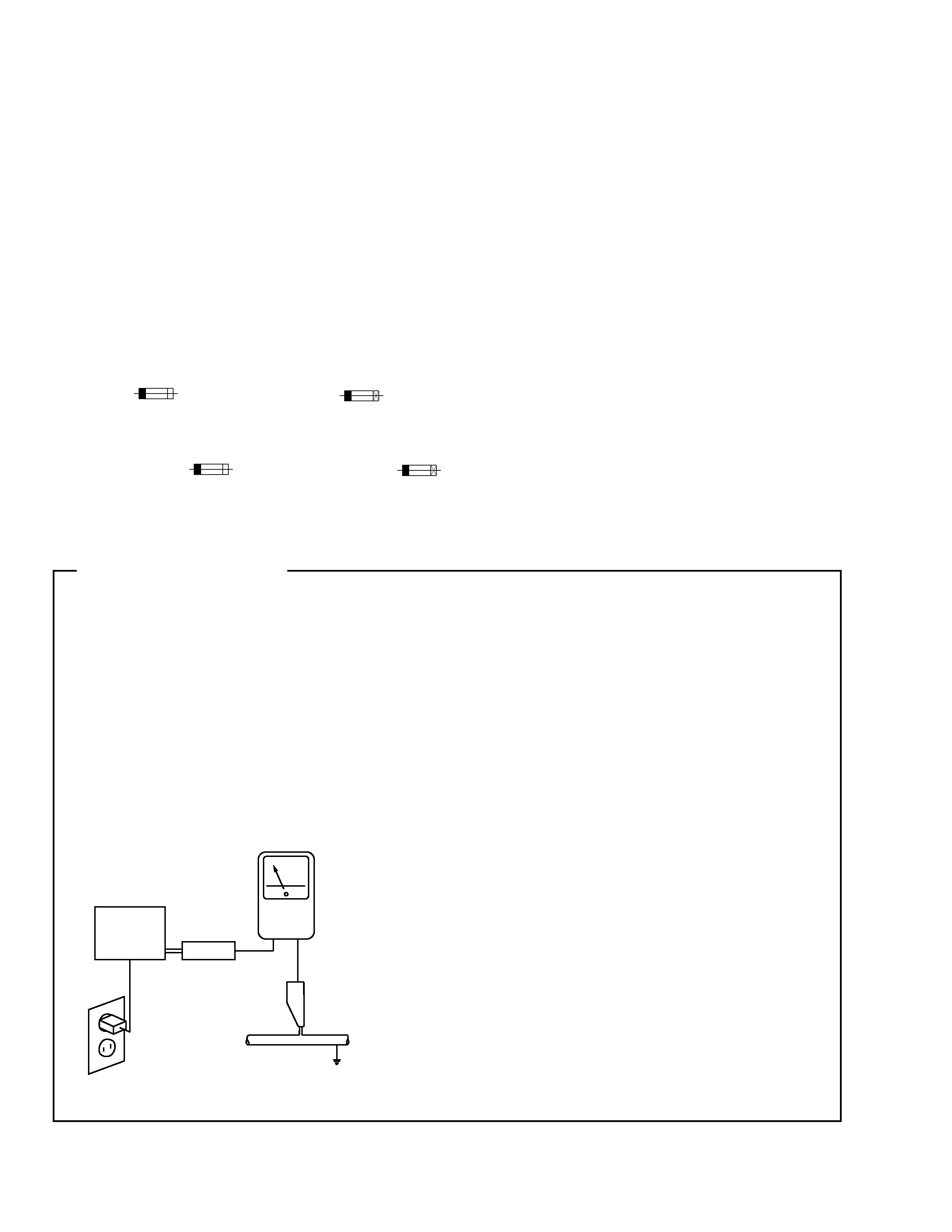
LEAKAGE CURRENT CHECK
Measure leakage current to a known earth ground (water pipe,
conduit, etc.) by connecting a leakage current tester such as Simpson
Model 229-2 or equivalent between the earth ground and all exposed
metal parts of the appliance (input/output terminals, screwheads,
metal overlays, control shaft, etc.). Plug the AC line cord of the
appliance directly into a 120V AC 60Hz outlet and turn the AC power
switch on. Any current measured must not exceed 0.5mA.
ANY MEASUREMENTS NOT WITHIN THE LIMITS OUTLINED
ABOVE ARE INDICATIVE OF A POTENTIAL SHOCK HAZARD
AND MUST BE CORRECTED BEFORE RETURNING THE
APPLIANCE TO THE CUSTOMER.
2. PRODUCT SAFETY NOTICE
Many electrical and mechanical parts in the appliance
have special safety related characteristics. These are often
not evident from visual inspection nor the protection afforded
by them necessarily can be obtained by using replacement
components rated for voltage, wattage, etc. Replacement parts
which have these special safety characteristics are identified
in this Service Manual.
Electrical components having such features are identified
by marking with a on the schematics and on the parts list in
this Service Manual. The use of a substitute replacement
component which does not have the same safety characteristics
as the PIONEER recommended replacement one, shown in
the parts list in this Service Manual, may create shock, fire, or
other hazards.
Product Safety is continuously under review and new
instructions are issued from time to time. For the latest
information, always consult the current PIONEER Service
Manual. A subscription to, or additional copies of, PIONEER
Service Manual may be obtained at a nominal charge from
PIONEER.
(FOR USA MODEL ONLY)
+
-
Reading should
not be above
0.5mA
Leakage
current
tester
Device
under
test
Test all
exposed metal
surfaces
Earth
ground
Also test with
plug reversed
(Using AC adapter
plug as required)
AC Leakage Test
S-FCRW210-K
S-FCRW710-K
3
2.1 SUBWOOFER
¶ POWER AMP SECTION
Remove the 8 screws from the power amplifier.
Remove the connector lead, etc.
¶ FRONT PANEL
The front panel is attached to the cabinet by its bosses
applied with adhesive.
To detach it, pry it open by inserting a flat blade
screwdriver into bottom slot between the cabinet and front
panel.
¶ SPEAKER
To detach first remove the front panel, then remove the
4 external screws.
3. PACKING EXPLODED VIEWS AND PARTS LIST
NOTES:
¶ Parts marked by "NSP" are generally unavailable because they are not in our Master Spare Parts List.
¶ The mark found on some component parts indicates the importance of the safety factor of the part. Therefore,whenreplacing,besure to use parts
of identical designation.
¶ Parts marked by " " are not always kept in stock. Their delivery time may be longer than they may be unavailable.
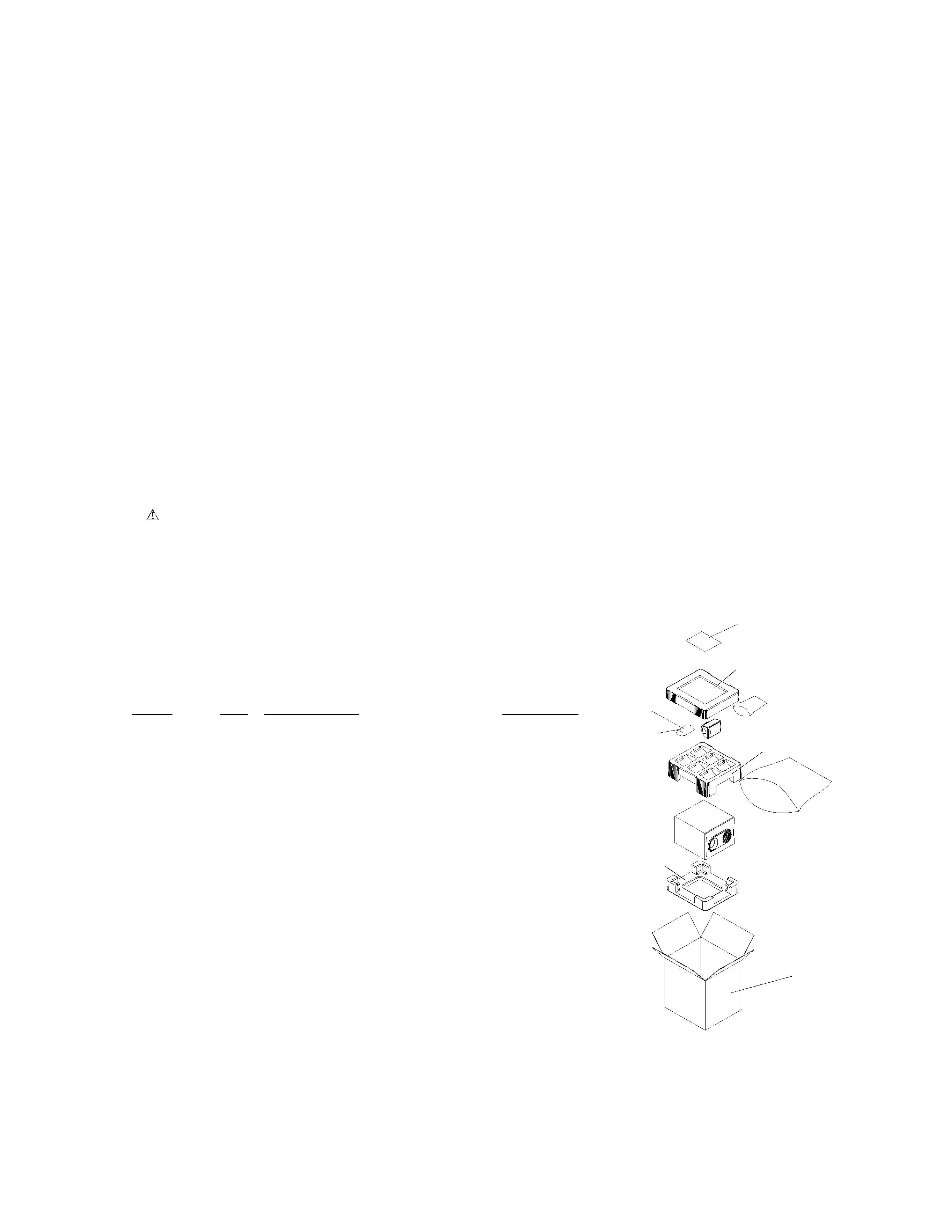
3.1 PACKING
Parts List
Mark
No.
Description
Parts No.
1
Instruction Manual
277854
2
RCA Pin Cable
277681
3
Speaker Wire (PNK/WHT)
277636
4
Speaker Wire (BLU/WHT)
277641
5
Speaker Wire (YEL/WHT)
277656
6
Speaker Wire (ORG/WHT)
277661
7
Speaker Wire (GRN/WHT)
277676
8
Speaker Wire (PPL/WHT)
278124
9
Rubber Foot (A) Set
277963
10
Rubber Foot (B) Set
277978
11
Styro Pad Top
277527
12
Styro Pad Mid
277532
13
Styro Pad Bottom
277547
14
Packing Case (210/KUXC)
277483
15
Packing Case (210/KCXC)
278080
16
Packing Case (710/KUXC)
278095
17
Speaker Wire + Foot Assy (210)
277983
18
Speaker Wire + Foot Assy (710)
278119
2. DISASSEMBLY
2.2 SATELLITE
¶ METAL GRILLE
The metal grill is attached to the cabinet by butyl rubber.
To detach it, pull it away by a hook.
1
2-10
11
12
13
14, 15, or 16
17, 18
S-FCRW210-K
S-FCRW710-K
4
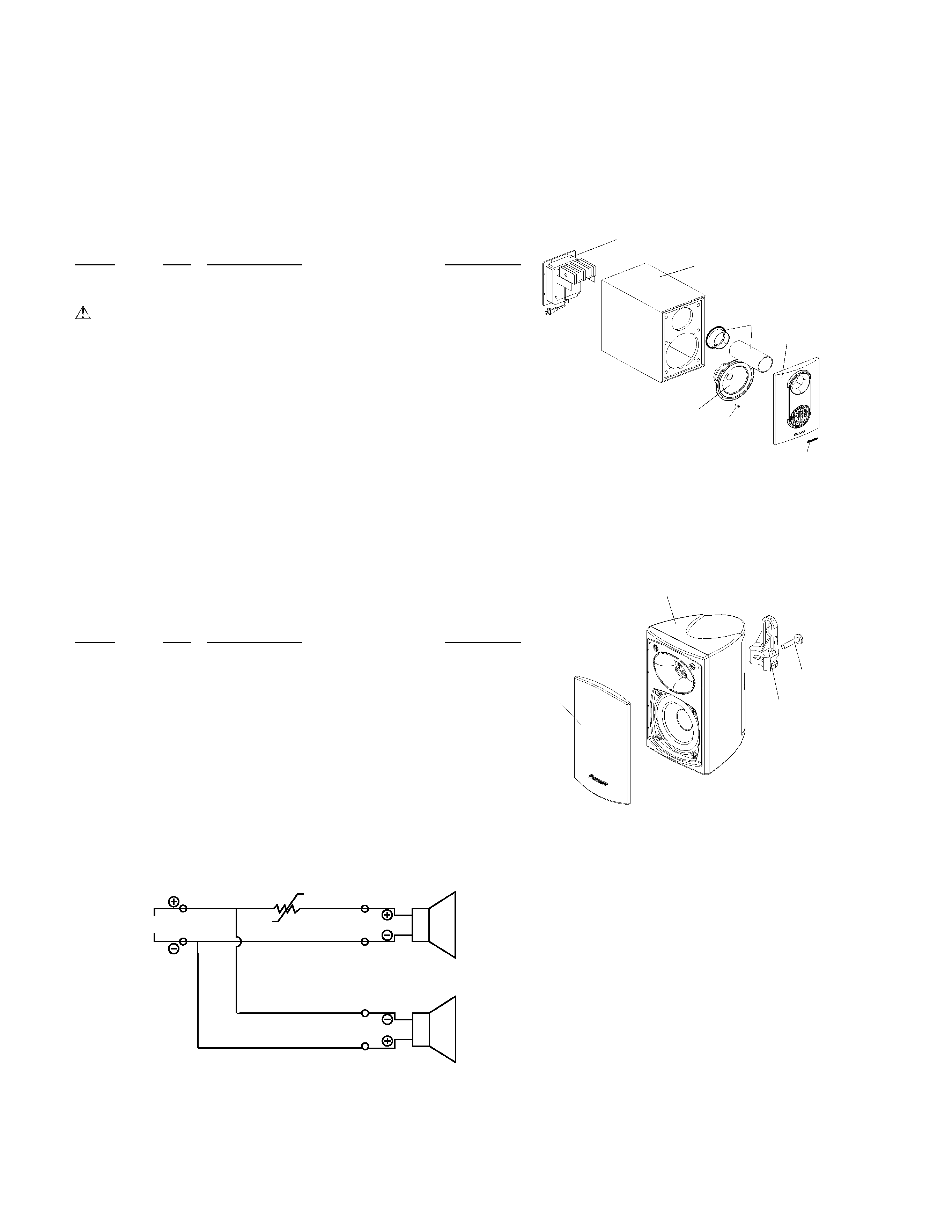
3.2 EXTERIOR SECTION
3.2.1 POWERED SUBWOOFER
Parts List
Mark
No.
Description
Parts No.
NSP
1
Cabinet
277478
NSP
2
Amplifier Assy (HTP-A3)
277374
3
Front Panel
277443
4
Port Flare Assy
278000
5
Woofer
277572
NSP
6
Logo Badge
277458
7
Woofer Gasket
277745
8
Port Gasket
277750
9
Screw for Woofer + AMP
278015
3.2.2 SATELLITE SPEAKER
Parts List
Mark
No.
Description
Parts No.
1
Satellite Front/Center Assy (210)
278020
2
Satellite Front/Center Assy (710)
278164
3
Satellite Rear Assy (210)
278060
4
Satellite Rear Assy (710)
278184
5
Metal Grill with Logo
278040
6
Bracket
277403
7
Screw for Bracket
278055
SCHEMATIC DIAGRAM
YEL
BLK
Woofer
RED
BLK
RED
BLK
Tweeter
P.SW 1.1A
INPUT
1
3
5
6
9
2
4
5
1, 2, 3, or 4
6
7
S-FCRW210-K
S-FCRW710-K
5
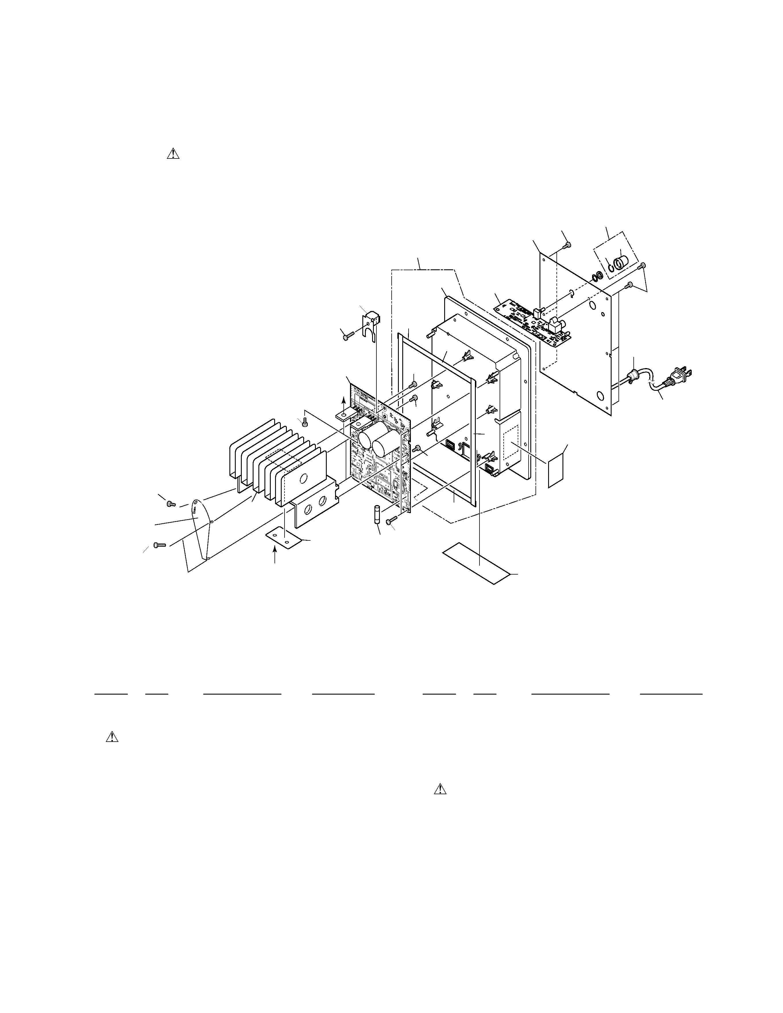
3.3 POWER AMP SECTION
NOTES :
¶ Parts marked by " NSP " are generally unavailable because they are not in our Master Spare Parts List.
¶ The
mark found on some component parts indicates the importance of the safety factor of the part. Therefore, when replacing,
be sure to use parts of identical designation.
¶ Screw adjacent to mark on the product are used for disassembly.
Mark
No.
Description
Parts No.
1
AC Power Cord
PDG1064
2
OPERATION ASSY AWU7761
3
Operation Panel
ANC8006
NSP
4
Heat Sink
ANH7117
5
Screw
ABA1052
6
AMP ASSY
AWU7760
7
Screw
BPZ30P080FZK
8
Rear Case Assy
AXG7085
9
Cord Stopper
CM22C
10
Air Packing L
AEB7172
11
Air Packing S
AEB7174
Mark
No.
Description
Parts No.
12
Rear Case
AMC7039
13
Mica Sheet
AEE7033
14
Vol Knob Assy
PXA1621
NSP
15
Vol Knob
PAC1951
NSP
16
Spring
PBH1229
17
Fuse ( FU 1 ) 5A
REK1067
18
Fuse Caution Label ARW7083
19
ICP 65 Label
ARW7084
20
PBS Holder
ANG7329
21
Screw
IPZ30P120FMC
22
HS Holder
ANG7397
7
7
7
7
7 EXTERIOR SECTION PARTS LIST
A
A
11
17
21
19
4
5
21
6
21
5
5
5
9
1
7
15
16
7
3
10
11
10
2
12
8
18
14
20
13
5
22