ORDER NO.
PIONEER CORPORATION 4-1, Meguro 1-chome, Meguro-ku, Tokyo 153-8654, Japan
PIONEER ELECTRONICS (USA) INC. P.O. Box 1760, Long Beach, CA 90801-1760, U.S.A.
PIONEER EUROPE NV Haven 1087, Keetberglaan 1, 9120 Melsele, Belgium
PIONEER ELECTRONICS ASIACENTRE PTE. LTD. 253 Alexandra Road, #04-01, Singapore 159936
PIONEER CORPORATION 2006
RRV3384
T ZZS APR. 2006 Printed in Japan
SPEAKER SYSTEM
Front
Surround
Center
S-FCR3700
XTW/UC
This service manual is intended for qualified service technicians; it is not meant for the casual do-it-
yourselfer. Qualified technicians have the necessary test equipment and tools, and have been trained to
properly and safely repair complex products such as those covered by this manual.
Improperly performed repairs can adversely affect the safety and reliability of the product and may void the
warranty. If you are not qualified to perform the repair of this product properly and safely, you should not risk
trying to do so and refer the repair to a qualified service technician.
WARNING
This product contains lead in solder and certain electrical parts contain chemicals which are known to the state of California to
cause cancer, birth defects or other reproductive harm.
Health & Safety Code Section 25249.6 Proposition 65
2
1
23
4
12
3
4
C
D
F
A
B
E
S-FCR3700
1. FOR PRECAUTION OF REASSEMBLY AND DISASSEMBLY
GRILLE
The grille is attached to the cabinet by its bosses applied with
adhesive.
To detach it, pry it open by inserting a flat blade screwdriver
into lower right and lower left slot.
To attach it, apply adhesive to the holes on the baffle. Then
press it to the baffle.
CAUTION
There are 10 bosses for press-fitting at the grille. To detach the
grille, remove in order from lower bosses. (Refer to thefigure in
page 4.) In order not to damage the bosses, don't remove it
forcibly. Pry it open little by little. Be sure to insert a flat blade
screwdriver from just beside of its bosses.
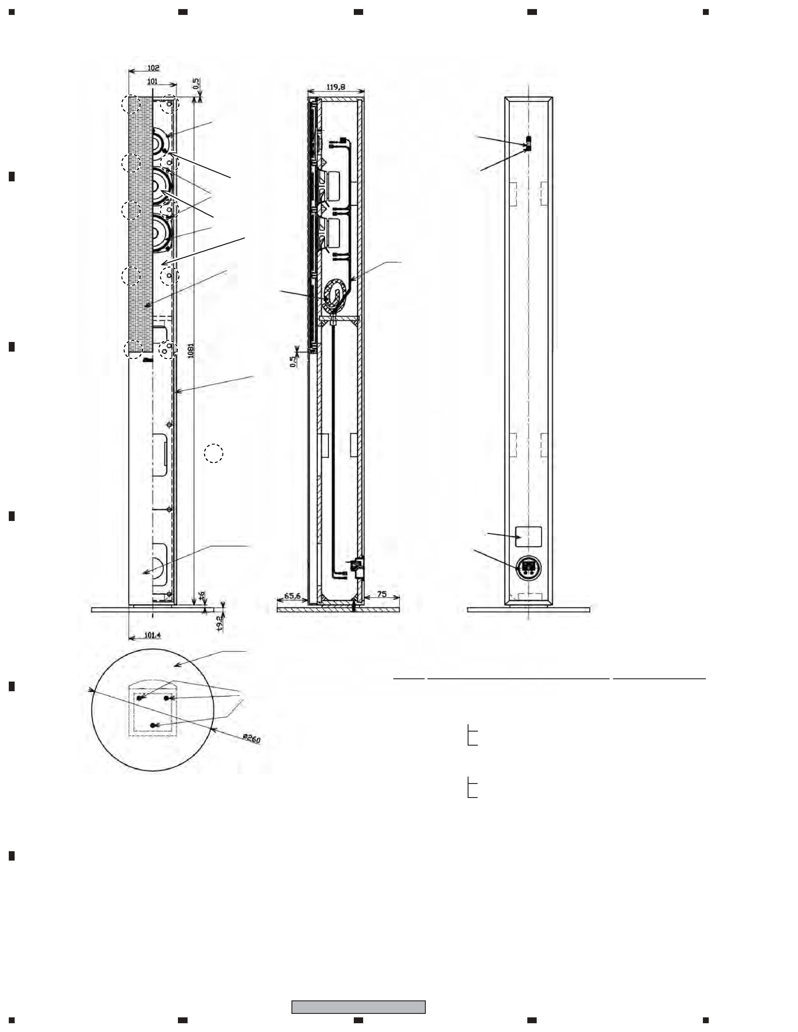
WOOFER
The woofer is attached to the baffle by 4 external screws.
To detach it, unfasten those screws.
To detach it, first remove the grille. Then remove the screws.
When attaching it, face its terminal downward.
TWEETER
The tweeter is attached to the baffle by 3 external screws.
To detach it, unfasten those screws.
To detach it, first remove the grille. Then remove the screws.
When attaching it, face its terminal leftward and rightward.
COSMETIC PANEL
The cosmetic panel is attached to the baffle by its bosses.
To detach it, pry it open by inserting a flat blade screwdriver
into lower slot.
To detach it, first remove the speaker stand base and grille.
Then remove the cosmetic panel.
When attaching it, fit the boss into the hole on the baffle.
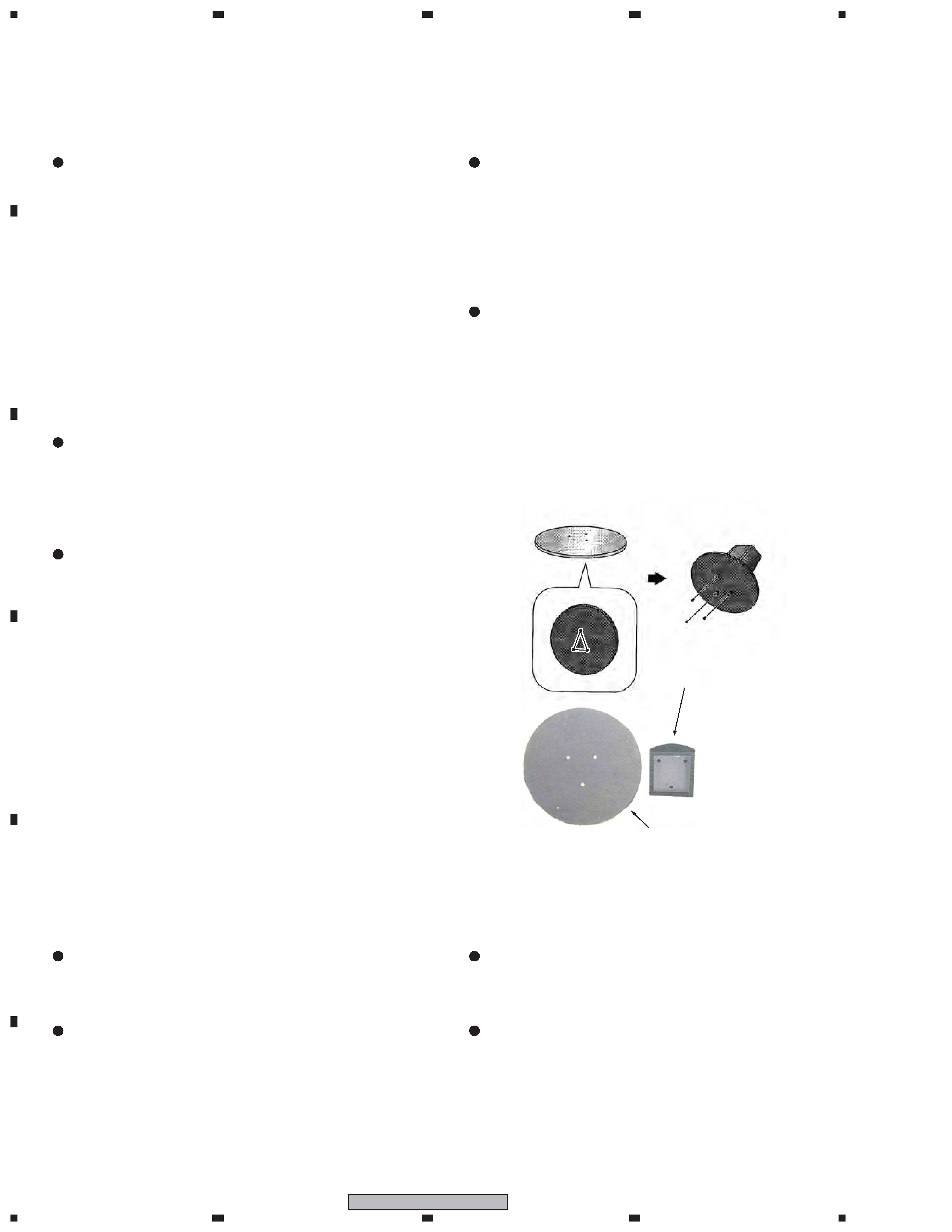
SPEAKER STAND BASES
The speaker stand base is attached to the bottom of cabinet by 3
external screws.
To detach it, unfasten those screws.
Attach the speaker stand bases to the stems using the screws
provided. Once you have aligned the stem and base, secure
with the small screws at the points shown below. Note that the
speaker should face in the direction of the base of the isosceles
triangle (outlined below).
GRILLE
The grille assy is attached to the cabinet by 8 external screws.
To detach it ,unfasten those screws.
SPEAKER UNIT
The speaker unit, together with the grille assy, is attached to the
cabinet by 4 external screws.
To detach it, first remove the grille assy. Next remove the cabi-
net. Then remove the cable.
When attaching it, face its terminal toward the input terminal.
1.1
FRONT SPEAKER
1.2
CENTER SPEAKER
Rear
Front
Stem
(the bottom of cabinet)
Speaker Stand Base
1.3
SURROUND SPEAKER
GRILLE
The grille is attached to the cabinet by 6 external screws. To
detach it, unfasten those screws.
SPEAKER UNIT
The speaker unit, together with the grille, is attached to the
cabinet by 4 external screws. To detach it, first unfasten those
screws. Next remove the cabinet. Then remove the cable. When
attaching it, face its terminal downward.
3
1
23
4
1
2
3
4
C
D
F
A
B
E
S-FCR3700
Parts marked by "NSP" are generally unavailable because they are not in our Master Spare Parts List.
The
mark found on some component parts indicates the importance of the safety factor of the part.
Therefore, when replacing, be sure to use parts of identical designation.
NOTES:
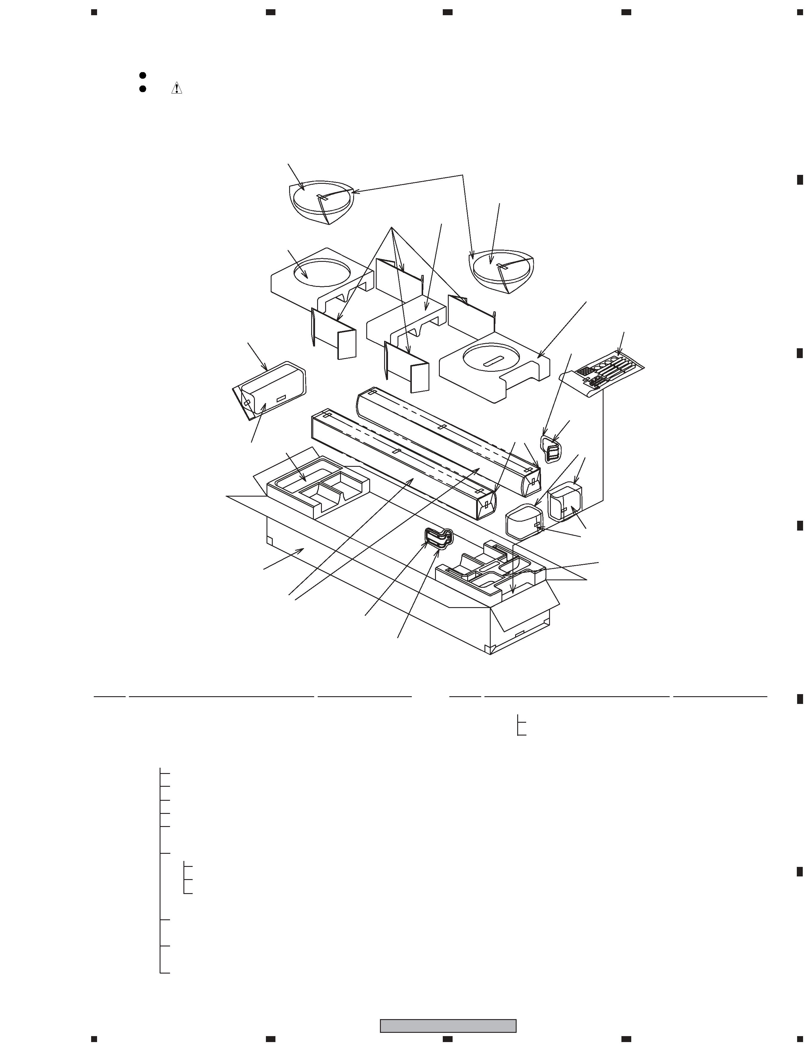
2. EXPLODED VIEWS AND PARTS LIST
2.1
PACKING
11
7
7
4
8 (2/2)
14
6
5
9
15
13
8 (1/2)
10 (1/2)
16
1
5
2
12
6
10 (2/2)
3
NSP
Stand Set
SEA6052
5
Speaker Stand
SNK2922
6
Polyethylene Bag S1
SHL1414
7
Speaker Stand Base
SMS6027
8
Protector
SHA6112
9
Protector (Middle)
SHA6118
10 Protector
SHA6113
11 Protection Sheet
SHC6051
12 Protection Sheet
SHC6052
13 Polyethylene Bag S2
SHL1417
14 Polyethylene Bag S2
SHL1420
15 Spacer
SHB6014
16 Packing Case
SHG6228
NSP
Model Label (FL)
SAN6377
NSP
Model Label (FR)
SAN6378
NSP
Model Label (SL)
SAN6379
NSP
Model Label (SR)
SAN6380
NSP
Model Label (C)
SAN6381
NSP
Caution Label (for Surround)
SRW1075
NSP
1
Front Speaker
SMW6205
NSP
2
Center Speaker
SMW6206
NSP
3
Surround Speaker
SMW6207
NSP
4
Accessory Set
SME6088
Speaker Cord (FL: White)
SDS6037
Speaker Cord (FR: Red)
SDS6038
Speaker Cord (SL: Blue)
SDS6039
Speaker Cord (SR: Gray)
SDS6040
Speaker Cord (C: Green)
SDS1173
NSP
Screw Set
SME6073
Screw (for Speaker Stand) CMZ50P120FNC
Screw (for Speaker Stand Base) CYC40P250FTC
Polyethylene Bag S0
SHL1314
Non Skid Pad
SEP6015
(for Speaker Stand Base)
Non Skid Pad
SEP6016
(for Center Speaker)
Polyethylene Bag S1
SHL1251
PACKING Parts List
Mark No.
Description
Part No.
Mark No.
Description
Part No.
4
1
23
4
12
3
4
C
D
F
A
B
E
S-FCR3700
5
10
11 (x3)
12 (x8)
2
7
6
9
1
8(x2)
3
4
Model Label
Speaker Stand Base
( refer to 2.1 PACKING
/ No.7 )
Screw
( refer to 2.1 PACKING
/ No.4 Accessory Set )
12 (x2)
: the bosses of
the grille
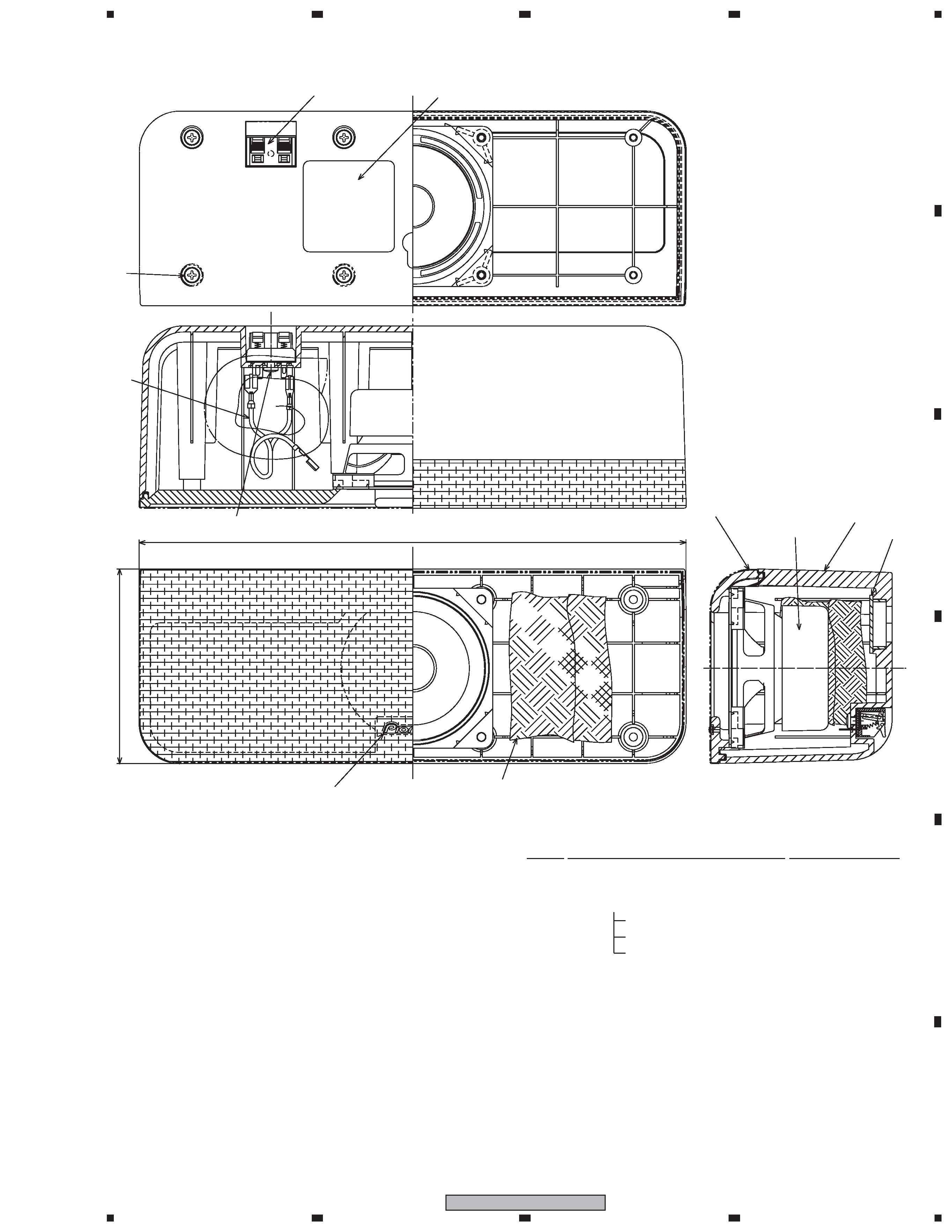
FRONT SPEAKER Parts List
NSP
1
Cabinet
SMM6043
2
Grille
SMG6109
NSP
Grille Cloth
SAS6068
NSP
Grille Frame
SMH6017
3
Cosmetic Plate Assy
SXB6004
NSP
Badge
SAM1507
NSP
Cosmetic Plate
SNK6131
4
Input Terminal
SKX1060
5
Fastener
SNB1073
6
Network Assy
SWN6021
NSP
7
Acoustic Absorbent
SMT6015
NSP
8
Packing
SEC6083
9
Speaker (Woofer)
K77DC55-51L
10
Speaker (Tweeter)
FK26AP32-54L
11
Screw (for Tweeter)
BYC35P160FTB
12
Screw (for Woofer, Fastener)
BYC35P120FTB
2.2
FRONT SPEAKER
Mark No.
Description
Part No.
5
1
23
4
1
2
3
4
C
D
F
A
B
E
S-FCR3700
CENTER SPEAKER Parts List
NSP
1
Cabinet
SNK2925
2
Grille
SMG1868
NSP
3
Badge 28
SAM1506
NSP
Grille Cloth
SAS1607
NSP
Baffle
SNK2926
4
Connecting Cord
SDD1345
5
Input Terminal
SKX1096
NSP
6
Acoustic Absorbent (White)
SMT1293
NSP
7
Plastic Cap
SNK2790
8
Speaker
K77DC55-52F
9Screw (for Input Terminal)
BPZ35P080FTC
10
Screw (for Cabinet)
BPZ35P120FTB
>PS<
6 (x2)
7
Model Label
3
10
(x8)
9
4
270
96
5
8
2
1
Mark No.
Description
Part No.
2.3
CENTER SPEAKER