ORDER NO.
PIONEER CORPORATION 4-1, Meguro 1-chome, Meguro-ku, Tokyo 153-8654, Japan
PIONEER ELECTRONICS (USA) INC. P.O. Box 1760, Long Beach, CA 90801-1760, U.S.A.
PIONEER EUROPE NV Haven 1087, Keetberglaan 1, 9120 Melsele, Belgium
PIONEER ELECTRONICS ASIACENTRE PTE. LTD. 253 Alexandra Road, #04-01, Singapore 159936
PIONEER CORPORATION 2006
Model
Type
Power Requirement
Remarks
S-EW2
MXCN
AC 220 to 230 V
S-EW2
MAXCN5
AC 220 to 230 V
S-EW2
MLXCN
AC 220 to 230 V
RRV3422
POWERED SUBWOOFER
S-EW2
T ZZS AUG. 2006
SAFETY INFORMATION ...................................... 2
1. SPECIFICATIONS ................................................ 4
2. EXPLODED VIEWS AND PARTS LIST ................ 5
3. SCHEMATIC DIAGRAM ........................................ 8
4. PCB CONNECTION DIAGRAM .......................... 10
5. PCB PARTS LIST ............................................... 14
6. ADJUSTMENT .................................................... 15
CONTENTS
7. GENERAL INFORMATION ................................ 16
7.1 DISASSEMBLY ........................................... 16
8. PANEL FACILITIES ............................................ 19
For details, refer to "Important Check Points for good servicing".
THIS MANUAL IS APPLICABLE TO THE FOLLOWING MODEL(S) AND TYPE(S).
-NOTE
The removed "Rubber Foot / 136-10020-350" are not reusable.
When repairing, be sure to prepare new "Rubber Foot / 136-10020-350".
2
1
23
4
12
3
4
C
D
F
A
B
E
S-EW2
SAFETY INFORMATION
1. SAFETY PRECAUTIONS
The following check should be performed for the
continued protection of the customer and service
technician.
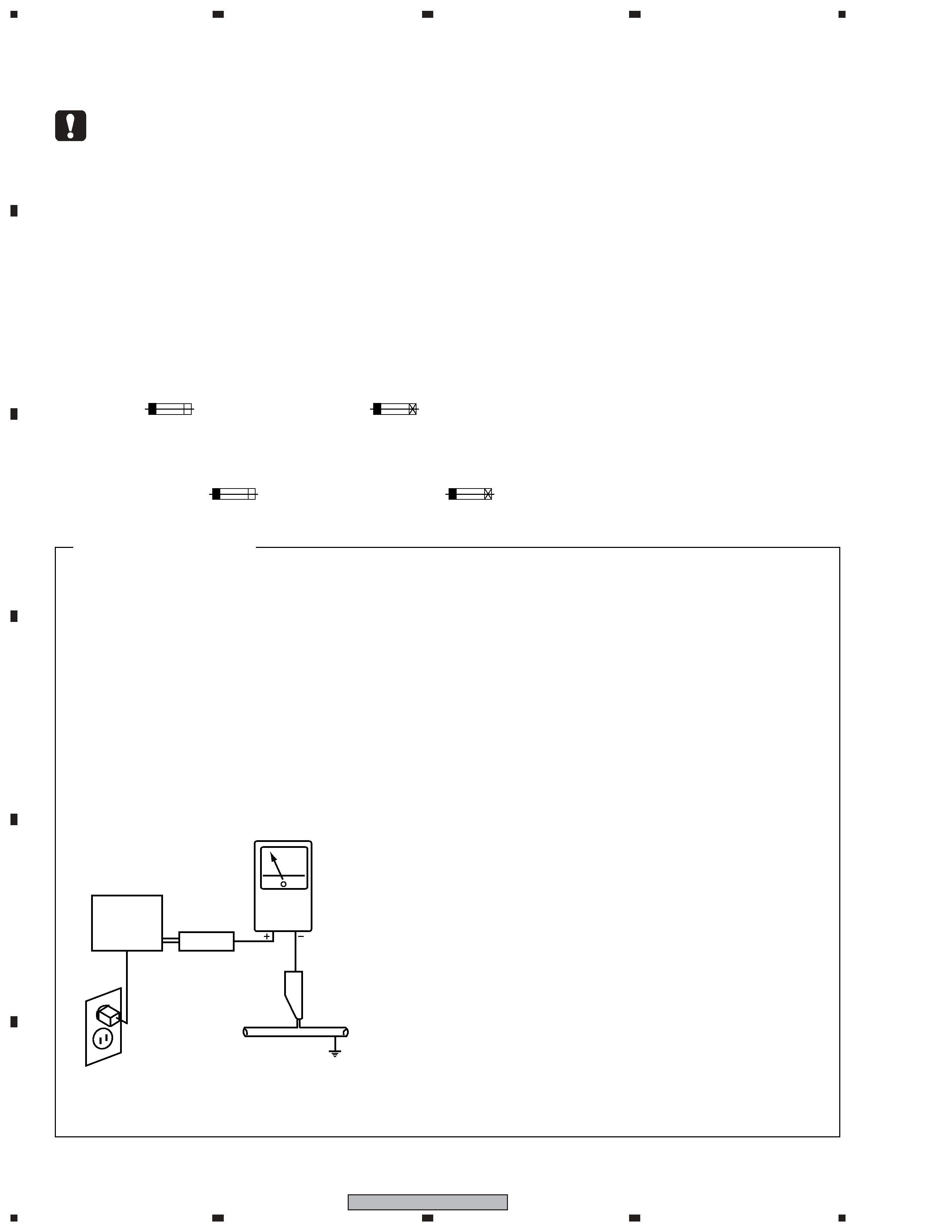
LEAKAGE CURRENT CHECK
Measure leakage current to a known earth ground
(water pipe, conduit, etc.) by connecting a leakage
current tester such as Simpson Model 229-2 or
equivalent between the earth ground and all exposed
metal parts of the appliance (input/output terminals,
screwheads, metal overlays, control shaft, etc.). Plug
the AC line cord of the appliance directly into a 120V
AC 60 Hz outlet and turn the AC power switch on. Any
current measured must not exceed 0.5 mA.
ANY MEASUREMENTS NOT WITHIN THE LIMITS
OUTLINED ABOVE ARE INDICATIVE OF A POTENTIAL
SHOCK HAZARD AND MUST BE CORRECTED BEFORE
RETURNING THE APPLIANCE TO THE CUSTOMER.
2. PRODUCT SAFETY NOTICE
Many electrical and mechanical parts in the appliance
have special safety related characteristics. These are
often not evident from visual inspection nor the protection
afforded by them necessarily can be obtained by using
replacement components rated for voltage, wattage, etc.
Replacement parts which have these special safety
characteristics are identified in this Service Manual.
Electrical components having such features are
identified by marking with a > on the schematics and on
the parts list in this Service Manual.
The use of a substitute replacement component which
does not have the same safety characteristics as the
PIONEER recommended replacement one, shown in the
parts list in this Service Manual, may create shock, fire,
or other hazards.
Product Safety is continuously under review and new
instructions are issued from time to time. For the latest
information, always consult the current PIONEER Service
Manual. A subscription to, or additional copies of,
PIONEER Service Manual may be obtained at a nominal
charge from PIONEER.
Leakage
current
tester
Reading should
not be above
0.5 mA
Device
under
test
Test all
exposed metal
surfaces
Also test with
plug reversed
(Using AC adapter
plug as required)
Earth
ground
AC Leakage Test
(FOR USA MODEL ONLY)
WARNING
This product contains lead in solder and certain electrical parts contain chemicals which are known to the state of California to
cause cancer, birth defects or other reproductive harm.
Health & Safety Code Section 25249.6 - Proposition 65
NOTICE
(FOR CANADIAN MODEL ONLY)
Fuse symbols
(fast operating fuse) and/or
(slow operating fuse) on PCB indicate that replacement parts must
be of identical designation.
REMARQUE
(POUR MODÈLE CANADIEN SEULEMENT)
Les symboles de fusible
(fusible de type rapide) et/ou
(fusible de type lent) sur CCI indiquent que les pièces
de remplacement doivent avoir la même désignation.
This service manual is intended for qualified service technicians ; it is not meant for the casual do-it-
yourselfer. Qualified technicians have the necessary test equipment and tools, and have been trained
to properly and safely repair complex products such as those covered by this manual.
Improperly performed repairs can adversely affect the safety and reliability of the product and may
void the warranty. If you are not qualified to perform the repair of this product properly and safely, you
should not risk trying to do so and refer the repair to a qualified service technician.
3
1
23
4
1
2
3
4
C
D
F
A
B
E
S-EW2
[Important Check Points for Good Servicing]
In this manual, procedures that must be performed during repairs are marked with the below symbol.
Please be sure to confirm and follow these procedures.
1. Product safety
Please conform to product regulations (such as safety and radiation regulations), and maintain a safe servicing environment by
following the safety instructions described in this manual.
1 Use specified parts for repair.
Use genuine parts. Be sure to use important parts for safety.
2 Do not perform modifications without proper instructions.
Please follow the specified safety methods when modification(addition/change of parts) is required due to interferences such as
radio/TV interference and foreign noise.
3 Make sure the soldering of repaired locations is properly performed.
When you solder while repairing, please be sure that there are no cold solder and other debris.
Soldering should be finished with the proper quantity. (Refer to the example)
4 Make sure the screws are tightly fastened.
Please be sure that all screws are fastened, and that there are no loose screws.
5 Make sure each connectors are correctly inserted.
Please be sure that all connectors are inserted, and that there are no imperfect insertion.
6 Make sure the wiring cables are set to their original state.
Please replace the wiring and cables to the original state after repairs.
In addition, be sure that there are no pinched wires, etc.
7 Make sure screws and soldering scraps do not remain inside the product.
Please check that neither solder debris nor screws remain inside the product.
8 There should be no semi-broken wires, scratches, melting, etc. on the coating of the power cord.
Damaged power cords may lead to fire accidents, so please be sure that there are no damages.
If you find a damaged power cord, please exchange it with a suitable one.
9 There should be no spark traces or similar marks on the power plug.
When spark traces or similar marks are found on the power supply plug, please check the connection and advise on secure
connections and suitable usage. Please exchange the power cord if necessary.
0 Safe environment should be secured during servicing.
When you perform repairs, please pay attention to static electricity, furniture, household articles, etc. in order to prevent injuries.
Please pay attention to your surroundings and repair safely.
2. Adjustments
To keep the original performance of the products, optimum adjustments and confirmation of characteristics within specification.
Adjustments should be performed in accordance with the procedures/instructions described in this manual.
4. Cleaning
For parts that require cleaning, such as optical pickups, tape deck heads, lenses and mirrors used in projection monitors, proper
cleaning should be performed to restore their performances.
3. Lubricants, Glues, and Replacement parts
Use grease and adhesives that are equal to the specified substance.
Make sure the proper amount is applied.
5. Shipping mode and Shipping screws
To protect products from damages or failures during transit, the shipping mode should be set or the shipping screws should be
installed before shipment. Please be sure to follow this method especially if it is specified in this manual.
4
1
23
4
12
3
4
C
D
F
A
B
E
S-EW2
~ With playback of Dolby* Digital, establishment of a
special channel for the subwoofer is recommended; and
with playback of LFE (Low Frequency Effect: sound
effect like the rumbling of the earth, whose purpose is
to intensify the force of the video), the S-EW2 is
especially effective.
Dolby* Digital
Dolby Digital is the name of the Dolby Surround multi-
channel digital system that was developed from Dolby
Surround, as a continuation of Dolby Pro Logic Surround.
Dolby Digital is also referred to as a 5.1 channel system.
This is because it has 5 channels in the 20 Hz to 20 kHz
frequency range (front left and right, center , and rear left
and right) and an independent channel for the subwoofer.
The subwoofer channel is also referred to as LFE (Low
Frequency Effect).
The LFE channel is used according to individual tastes to
enhance the bass effect.
7 85 W power that serves video software playback such as
Dolby* Digital with a wide dynamic range.
7 Equipped with 16 cm driver
7 Turnover frequency can be continuous (50 Hz to 200 Hz).
7 Phase conversion switch (0°/180°).
* Maunfactured under license from Dolby Laboratories.
"Dolby" and the double-D symbol are trademarks of
Dolby Laboratories. Confidential unpublished works.
© 1992-1997 Dolby Laboratories. All rights reserved.
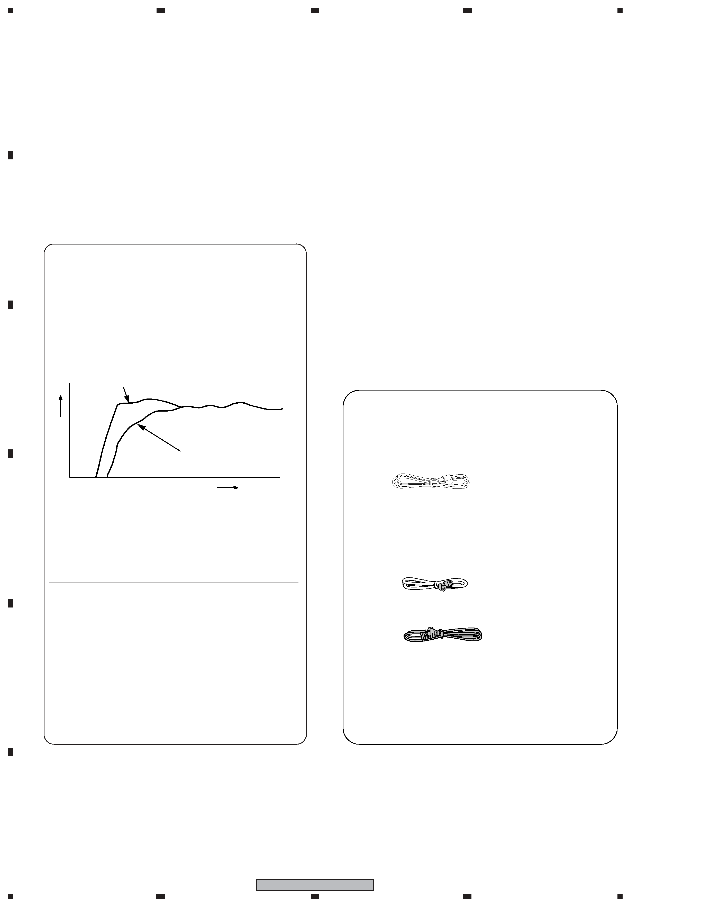
IN COMBINATION WITH SPEAKERS
The frequency characteristics of the S-EW2 combined with
small-size speakers are shown below. As shown in these
figures, the low frequency range is improved.
~ These special characteristics are obtained in an echoless
chamber. The effect of an additional S-EW2 in an
ordinary listening room is better than the chart indicates
when positioned adequately.
RESPONCE
(dB)
Small-size speaker
FREQUENCY (Hz)
Small-size speakers + S-EW2
ACCESSORY ITEMS
/ RCA plug cord x 1
(043-26302-511)
/ Operating instructions x 1
/ Power cord x 1
MAXCN5 type : 023-60120-101 (AC line cord set)
MXCN, MLXCN type : 023-60020-112 (AC line cord set)
Cabinet ......................................................... Floor type system
Speaker (Magnetically shielded type) ........... 16 cm cone type
Power Amplifier Continuous Power Output (RMS)
........................................................ 85 W/4
(30 Hz to 200 Hz)
÷ Above specifications are for when power supply is 230 V.
Input (sensitivity at 100 Hz/impedance)
LINE LEVEL (RCA jack)..................................... 180 mV/50 k
Turnover Frequency .......... 50 Hz to 200 Hz (continuously variable)
Outline Dimension ................. 300 (W) x 377 (H) x 404 (D) mm
Weight (without package) ............................................ 11.5 kg
Power Requirements ......................... 220 V to 230 V~, 50/60 Hz
Power Consumption ......................................................... 80 W
Accessories ................................................. RCA plug cord x 1
Operating instructions x 1
Warranty card x 1
Power cord x 1
NOTE:
Specifications and design subject to possible modification without
notice, due to improvements.
(only S-EW2/MAXCN5)
/ Warranty card x 1 (only S-EW2/MAXCN5)
1. SPECIFICATIONS
5
1
23
4
1
2
3
4
C
D
F
A
B
E
S-EW2
/ MAXCN5 type
Power Cord
Power Cord
/ MXCN, /MLXCN type
10
10
9
9
1
2
3
4
5
6
7
Mark No.
Description
Part No.
2. EXPLODED VIEWS AND PARTS LIST
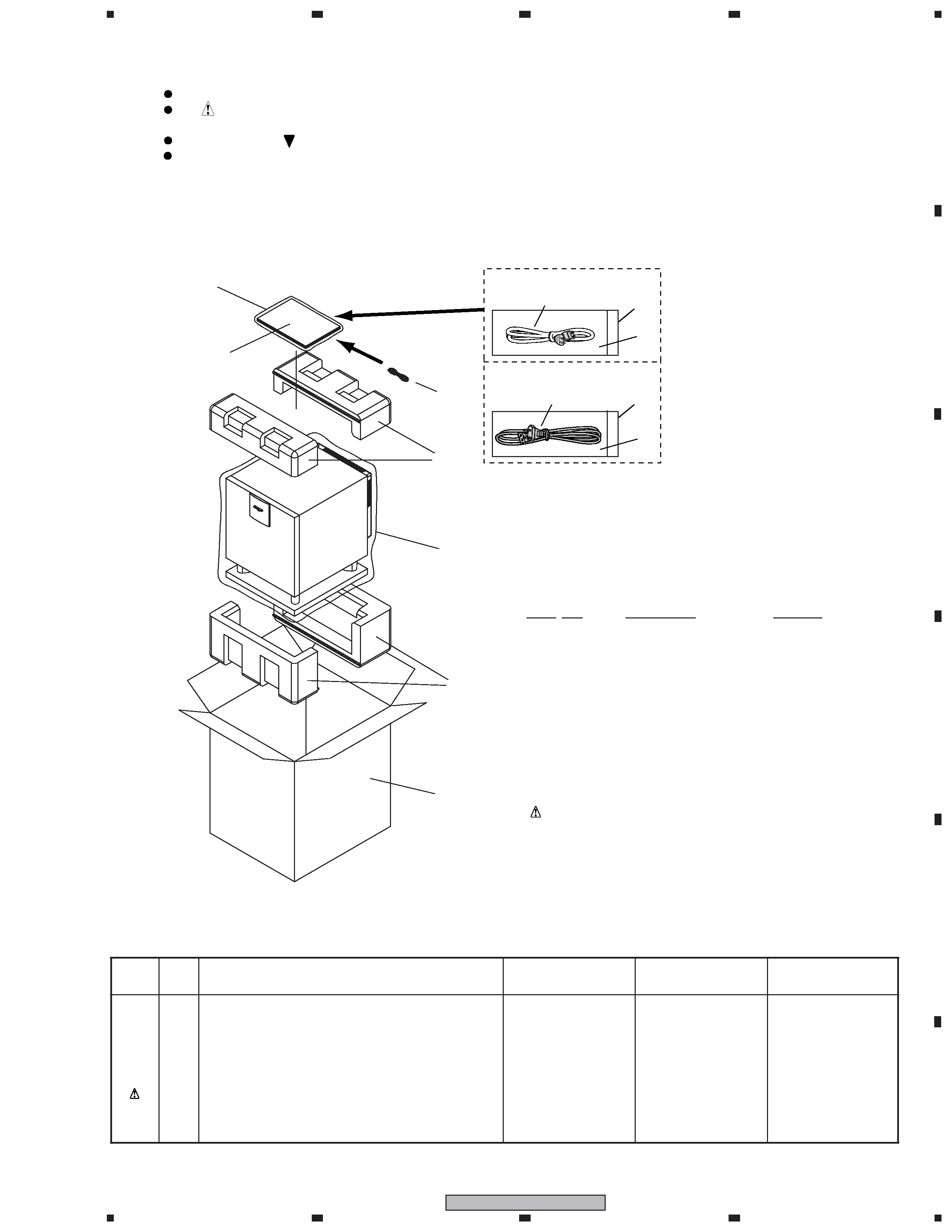
2.1 PACKING
Parts marked by "NSP" are generally unavailable because they are not in our Master Spare Parts List.
The
mark found on some component parts indicates the importance of the safety factor of the part.
Therefore, when replacing, be sure to use parts of identical designation.
Screws adjacent to
mark on product are used for disassembly.
For the applying amount of lubricants or glue, follow the instructions in this manual.
(In the case of no amount instructions, apply as you think it appropriate.)
NOTES:
(1) PACKING PARTS LIST
(2) CONTRAST TABLE
Mark
No
Description
S-EW2
S-EW2
S-EW2
/MXCN
/MAXCN5
/MLXCN
1
CARTON BOX
153-50900-2297
153-50900-4297
153-50900-3297
5
OPERATING INSTRUCTIONS
152-50900-1297
Not used
152-50900-1297
(English, Trad-Chinese)
5
OPERATING INSTRUCTIONS
Not used
152-50900-2297
Not used
(Simp-Chinese)
10
AC LINE CORD SET
023-60020-112
023-60120-101
023-60020-112
NSP
WARRANTY CARD
Not used
ARF7046
Not used
S-EW2/MXCN, S-EW2/MAXCN5 and S-EW2/MLXCN are constructed the same except for the following :
1
CARTON BOX
See Contrast table (2)
2
POLYFORM "BOTTOM"
149-50904-000
3
POLYBAG 28" x 34"
150-28034-510
4
POLYFORM "TOP"
149-50903-000
5
OPERATING INSTRUCTIONS
See Contrast table (2)
NSP
6
PE POLY BAG(I BOOK)E
150-10014-010
7
RCA PLUG CORD
043-26302-511
8· · · · · ·
9
POLYBAG 9 x 9
150-09009-510
10
AC LINE CORD SET
See Contrast table (2)
NSP
WARRANTY CARD
See Contrast table (2)