ORDER NO.
PIONEER CORPORATION 4-1, Meguro 1-chome, Meguro-ku, Tokyo 153-8654, Japan
PIONEER ELECTRONICS (USA) INC. P.O. Box 1760, Long Beach, CA 90801-1760, U.S.A.
PIONEER EUROPE NV Haven 1087, Keetberglaan 1, 9120 Melsele, Belgium
PIONEER ELECTRONICS ASIACENTRE PTE. LTD. 253 Alexandra Road, #04-01, Singapore 159936
PIONEER CORPORATION 2006
RRV3423
T ZZS JUNE 2006 Printed in Japan
SPEAKER SYSTEM
1. REASSEMBLY AND DISASSEMBLY PRECAUTIONS
1.1 FRONT and SURROUND SPEAKER
The grille assy is attached to the cosmetic baffle by catches.
Detach by pulling it toward you.
The catch is attached to the cosmetic baffle by press-fitting. To
detach it, insert a sharp-pointed tool like an eyeleteer into each
of side. To re-attach it, insert the holes of the cosmetic baffle
assy by press-fitting.
The cosmetic baffle is attached to the inner baffle by its bosses.
To detach it, pry it open by inserting a flat blade screwdriver
into lower side.
The woofer is attached to the inner baffle by 4 screws with the
screw heads facing the baffle. To detach it, first remove the cos-
metic baffle, next disconnect the cord to tweeter. Then unfasten
those screws. When re-attaching it, face its terminal upward.
The tweeter is attached to the cosmetic baffle by 2 internal
screws. To detach it, first remove the cosmetic baffle, next dis-
connect the cord to tweeter. Then unfasten those screws. When
re-attaching it, face its terminal downward.
Front
Center
Surround
Subwoofer
S-EV9V
XJM/E
S-EV9V XJM/NC
1.2 CENTER SPEAKER
The grille assy is attached to the cabinet by 8 external screws.
To detach it, unfasten those screws. When re-attaching it, the
connection cord should pass along the back side of the speaker
unit.
The speaker unit is attached to the grille by 4 internal screws.
To detach it, first remove the grille assy. Next unfasten those
screws, and remove the cable. When re-attaching it, face its ter-
minal leftward. (See to the backside of the grille assy.)
1.3 SUBWOOFER
The cosmetic baffle is attached to the cabinet by its bosses. To
detach it, pry it open by inserting a flat blade screwdriver into
lower slot. To attach it, clean the press-fitting part and apply a
bit of adhesive . Then press it to the baffle.
The woofer is attached to the back board of cabinet by 4 exter-
nal screws. To detach it, unfasten those screws. When re-at-
taching it, face its terminal upward.
2
1
23
4
12
3
4
C
D
F
A
B
E
S-EV9V
15
15
16
17
16
18
10
11
13
12
3
1
2
7
7
6
6
8
8
4
5
9, 14
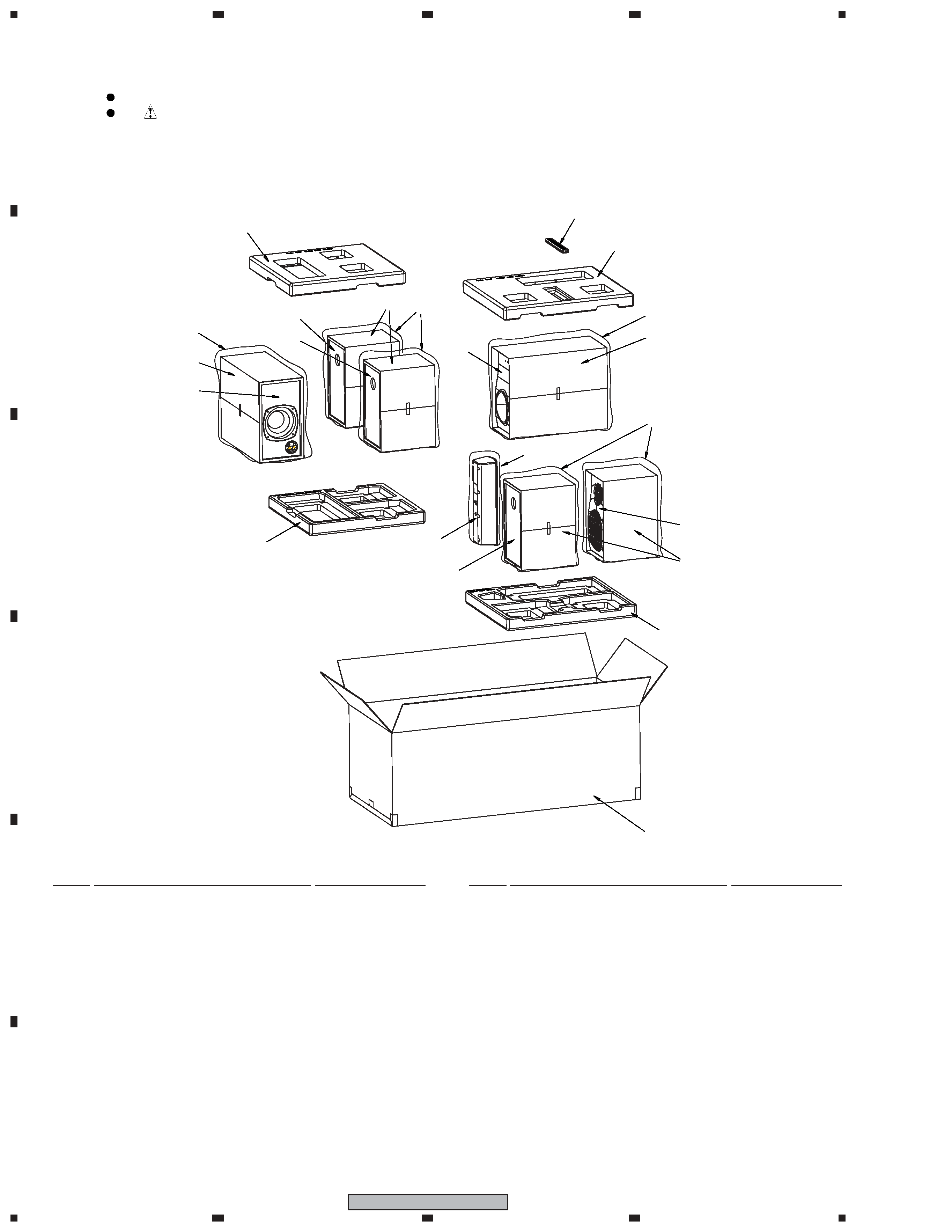
2.1 PACKING
Parts marked by "NSP" are generally unavailable because they are not in our Master Spare Parts List.
The
mark found on some component parts indicates the importance of the safety factor of the part.
Therefore, when replacing, be sure to use parts of identical designation.
NOTES:
Mark No.
Description
Part No.
PACKING Parts List
2. EXPLODED VIEWS AND PARTS LIST
Mark No.
Description
Part No.
NSP
1
Front Speaker (L)
SMW1955
NSP
2
Front Speaker (R)
SMW1956
NSP
3
Center Speaker
SMW1957
NSP
4
Surround Speaker (L)
SMW1961
NSP
5
Surround Speaker (R)
SMW1962
NSP
6
Subwoofer
SMW1963
7
Protection Sheet S2
SHC1826
8
Protection Sheet S4
SHC1827
9
Speaker Cord (for Subwoofer)
439929113167
10
Top Protector
439929364106
11
Bottom Protector
439929364107
12
Top Protector
439929364108
13
Bottom Protector
439929364109
14
Non Skid Pad
439929484271
NSP
15
Polyethylene Bag S5
SHL1430
NSP
16
Polyethylene Bag S7
SHL1434
NSP
17
Polyethylene Bag S4
SHL1433
for XJM/E type
18
Packing Case
439929334126
for XJM/NC type
18
Packing Case
439929334138
3
1
23
4
1
2
3
4
C
D
F
A
B
E
S-EV9V
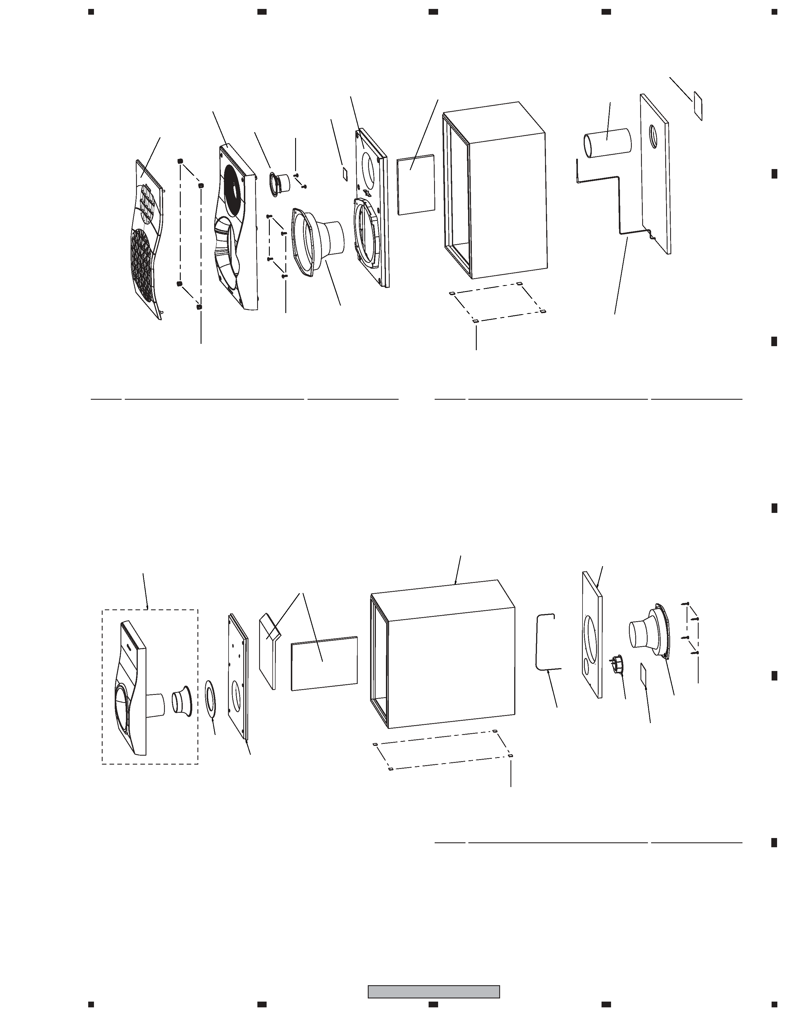
Acoustic Absorbent
Back Board
2
1
Model Label
5
4
Baffle Board
7
6
Wrap Board
3
Duct
Model Label
4
Gasket
8
7
Inner Baffle
1
5
3
2
6
Acoustic Absorbent
9 or 10
FRONT SPEAKER Parts List
Mark No.
Description
Part No.
2.2 FRONT SPEAKER
1
Speaker
A14LU80-53D
2
Screw
BRZ35P080FTC
3
Screw
BRZ40P100FTC
4
Speaker
E52AP39-63D
5
Catch
SNK2915
6
Rubber Foot
VEB1349
7
Cosmetic Baffle
439929418935
8
Grille Assy
829929752290
for Left channel
9
Network Assy
439929113173
for Right channel
10
Network Assy
439929113174
Mark No.
Description
Part No.
2.3 SUBWOOFER
SUBWOOFER Parts List
Mark No.
Description
Part No.
1
Speaker
A14LR80-51H
2
Screw
BYC40P200FTC
3
Rubber Foot
VEB1349
4
Input Terminal
439929050801
5
Connection Cord
439929110152
6
Gasket
439929484260
7Cosmetic Baffle Assy
829929752296
4
1
23
4
12
3
4
C
D
F
A
B
E
S-EV9V
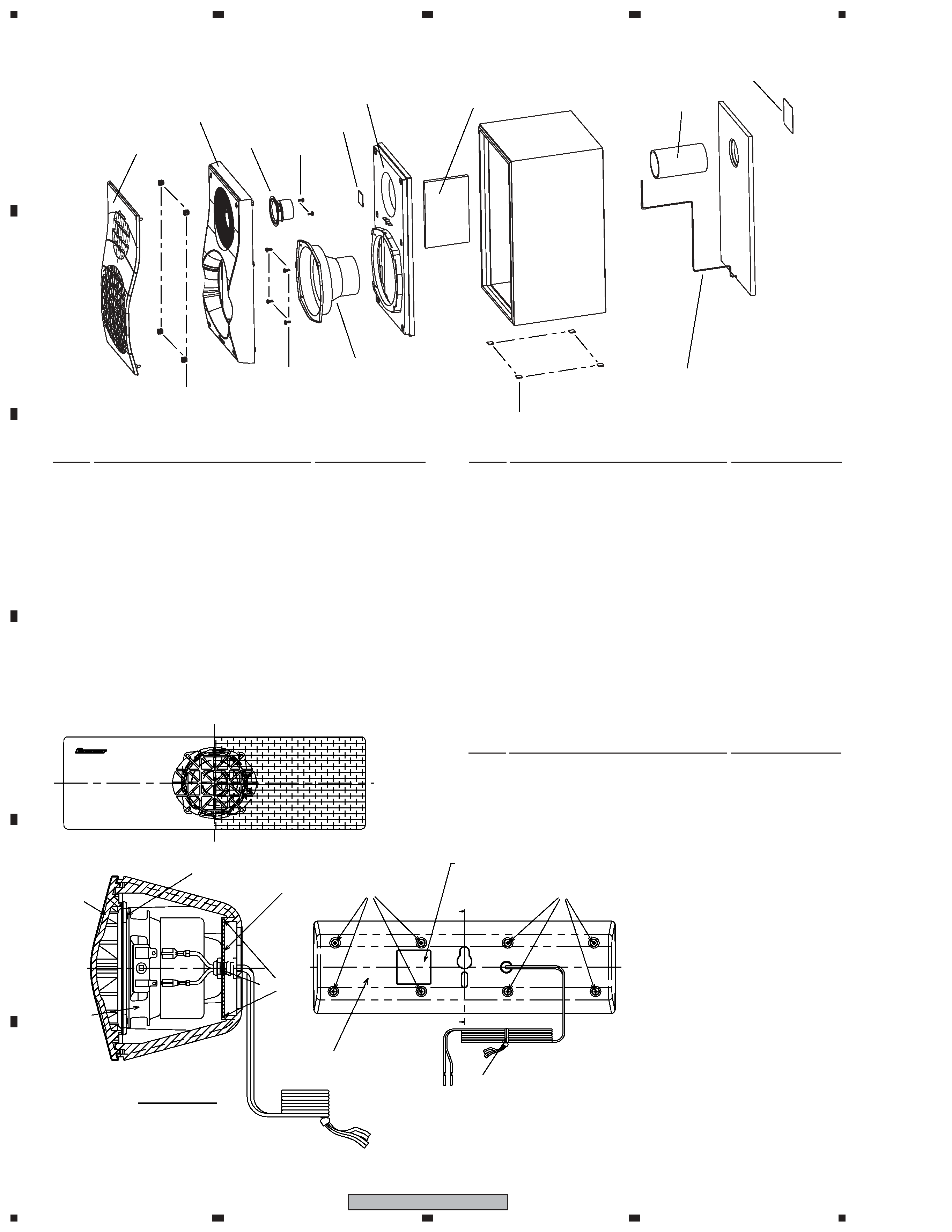
Duct
Model Label
4
Gasket
8
7
Inner Baffle
1
5
3
2
6
Acoustic Absorbent
9 or 10
2.4 SURROUND SPEAKER
2.5 CENTER SPEAKER
1
Screw
BPZ40P080FTC
2
Screw
BPZ40P100FTB
3
Speaker
K77DC55-53D
4
Grille Assy
QMG6001
5
Connection Cord
SDF1114
SURROUND SPEAKER Parts List
Mark No.
Description
Part No.
CENTER SPEAKER Parts List
Mark No.
Description
Part No.
A
A
Model Label
SECTION: AA
+
-
4
3
1 (x4)
Packing
5
2
2
Adhesive
Cabinet
1
Speaker
A14LU80-54D
2
Screw
BRZ35P080FTC
3
Screw
BRZ40P100FTC
4
Speaker
E52AP39-63D
5
Catch
SNK2915
6
Rubber Foot
VEB1349
7
Cosmetic Baffle
439929418935
8
Grille Assy
829929752290
for Left channel
9
Network Assy
439929113164
for Right channel
10
Network Assy
439929113165
Mark No.
Description
Part No.
5
1
23
4
1
2
3
4
C
D
F
A
B
E
S-EV9V
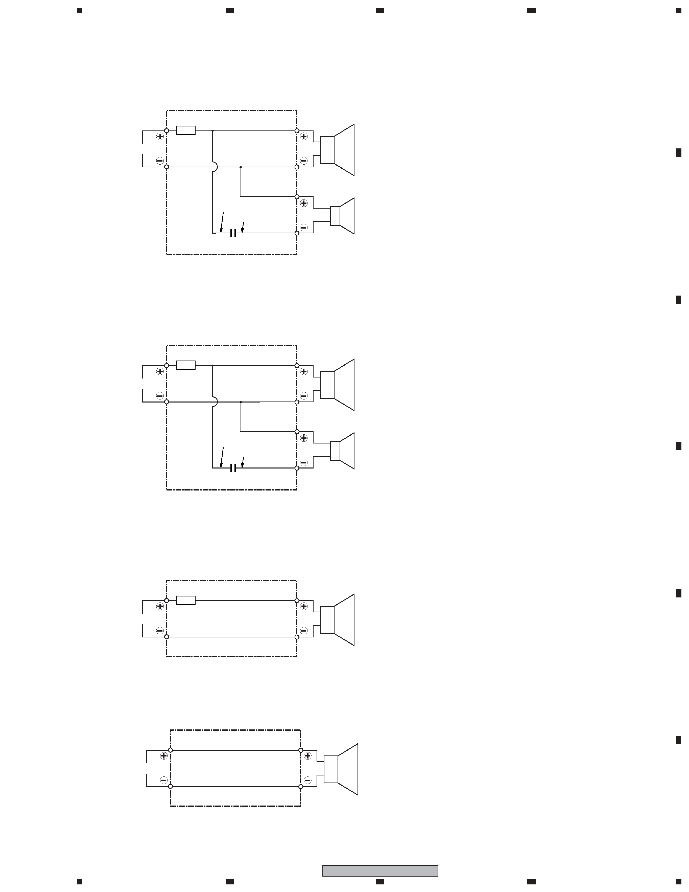
3. SCHEMATIC DIAGRAM
Network Assy (439929113173, 439929113174)
3.1 FRONT SPEAKER
2.2
µF/63 V
Long Leg
C
INPUT
Woofer
White
Tube color
439929113173: White (for Left channel)
439929113174: Red (for Right channel)
White with Gray Line
Black
Red
Tweeter
Short Leg
Tube
2.2
µF/63 V
Long Leg
C
INPUT
Woofer
White
Tube color
439929113164: Blue (for Left channel)
439929113165: Gray (for Right channel)
White with Gray Line
Black
Red
Tweeter
Short Leg
Tube
Network Assy (439929113164, 439929113165)
3.2 SURROUND SPEAKER
INPUT
Full-Range
Connection Cord (SDF1114)
3.3 CENTER SPEAKER
Tube color
SDF1114: Green
White
White with Gray Line
Tube
3.4 SUBWOOFER
INPUT
Woofer
Connection Cord (439929110152)
White
White with Gray Line