ORDER NO.
PIONEER CORPORATION 4-1, Meguro 1-chome, Meguro-ku, Tokyo 153-8654, Japan
PIONEER ELECTRONICS (USA) INC. P.O. Box 1760, Long Beach, CA 90801-1760, U.S.A.
PIONEER EUROPE NV Haven 1087, Keetberglaan 1, 9120 Melsele, Belgium
PIONEER ELECTRONICS ASIACENTRE PTE. LTD. 253 Alexandra Road, #04-01, Singapore 159936
PIONEER CORPORATION 2008
2008 Printed in Japan
EJECT
POWER
STOP
STOP
REAR
DISC
1
USB
1
USB
2
DISC
2
EJECT
MEP-7000
MULTI ENTERTAINMENT PLAYER
TRACK SEARCH
CUE/LOOP
EJECT
TIME
A.CUE
IN/CUE
HOT LOOP
LOOP
RELOOP/EXIT
PITCH BEND
BROWSE
MIX
EFFECT
UTILITY
MT
0
MASTER
TEMPO
TEMPO
6/10/16WIDE
OUT/ADJUST
FWD
TEMPO
REV
MEMORY
CALL
SEARCH
QUE
JO
G
B
R
E
A
K
SCR
ATC
H
TRACK SEARCH
CUE/LOOP
EJECT
TIME
A.CUE
IN/CUE
HOT LOOP
LOOP
RELOOP/EXIT
PITCH BEND
MT
0
MASTER
TEMPO
TEMPO
6/10/16WIDE
OUT/ADJUST
FWD
TEMPO
REV
MEMORY
CALL
SEARCH
QUE
JO
G
B
R
E
A
K
SCR
AT
CH
A
LOAD
B
MEP-7000
LOAD
MULTI ENTERTAINMENT PLAYER
CONTROL UNIT
DRIVE UNIT
MEP-7000
RRV3719
MULTI ENTERTAINMENT PLAYER
MEP-7000
THIS MANUAL IS APPLICABLE TO THE FOLLOWING MODEL(S) AND TYPE(S).
: This product comprises a control unit (CU-V170) and a drive unit. Note that
a user should bring in both units for servicing.
Model
Type
Power Requirement
Remarks.
MEP-7000
KUCXJ
AC 120 V
MEP-7000
WYXJ5
AC 220 V to 240 V
MEP-7000
TLFXJ
AC 110 V to 240 V
MEP-7000
WAXJ5
AC 220 V to 240 V
For details, refer to "Important Check Points for good servicing".
T-ZZR JULY
2
MEP-7000
1
2
3
4
A
B
C
D
E
F
1
2
3
4
SAFETY INFORMATION
This service manual is intended for qualified service technicians; it is not meant for the casual
do-it-yourselfer. Qualified technicians have the necessary test equipment and tools, and have been
trained to properly and safely repair complex products such as those covered by this manual.
Improperly performed repairs can adversely affect the safety and reliability of the product and may
void the warranty. If you are not qualified to perform the repair of this product properly and safely,
you should not risk trying to do so and refer the repair to a qualified service technician.
WARNING
This product contains certain electrical parts contain chemicals which are known to the State of California to cause cancer,
birth defects or other reproductive harm.
Health & Safety Code Section 25249.6 - Proposition 65
NOTICE
(FOR CANADIAN MODEL ONLY)
Fuse symbols
(fast operating fuse) and/or
(slow operating fuse) on PCB indicate that replacement parts must
be of identical designation.
REMARQUE
(POUR MODÈLE CANADIEN SEULEMENT)
Les symboles de fusible
(fusible de type rapide) et/ou
(fusible de type lent) sur CCI indiquent que les pièces
de remplacement doivent avoir la même désignation.
ANY MEASUREMENTS NOT WITHIN THE
LIMITS OUTLINED ABOVE ARE INDICATIVE
OF A POTENTIAL SHOCK HAZARD AND
MUST BE CORRECTED BEFORE RETURN-
ING THE APPLIANCE TO THE CUSTOMER.
2. PRODUCT SAFETY NOTICE
Many electrical and mechanical parts in the appliance
have special safety related characteristics. These are
often not evident from visual inspection nor the
protection afforded by them necessarily can be obtained
by using replacement components rated for voltage,
wattage, etc. Replacement par ts which have these
special safety character istics are identified in this
Service Manual.
Electr ical components having such features are
identified by marking with a
on the schematics and
on the parts list in this Service Manual.
The use of a substitute replacement component which
does not have the same safety characteristics as the
PIONEER recommended replacement one, shown in the
parts list in this Service Manual, may create shock, fire,
or other hazards.
Product Safety is continuously under review and new
instructions are issued from time to time. For the latest
infor mation, alw ays consult the current PIO N EER
Service Manual. A subscription to, or
additional copies
of, PIO N EER Ser vice Manual may be obtained at a
nominal charge from PIONEER.
(FOR USA MODEL ONLY)
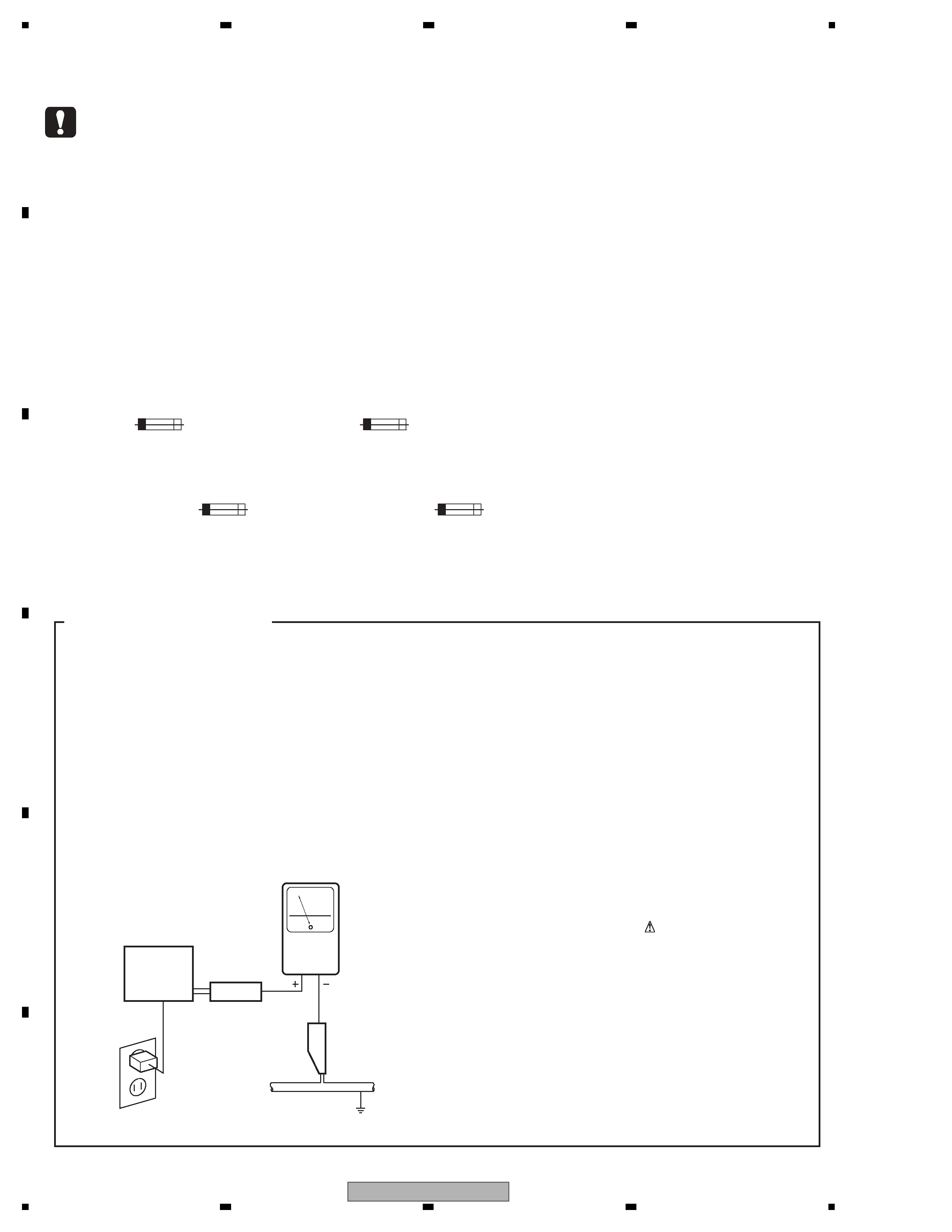
1. SAFETY PRECAUTIONS
The following check should be perfor med for the
contin ued protection of the customer and ser vice
technician.
LEAKAGE CURRENT CHECK
Measure leakage current to a known ear th ground
(water pipe, conduit, etc.) by connecting a leakage
current tester such as Simpson Model 229-2 or
equivalent between the ear th ground and all exposed
metal par ts of the appliance (input/output ter minals,
screwheads, metal overlays, control shaft, etc.). Plug
the AC line cord of the appliance directly into a 120V
AC 60 Hz outlet and turn the AC power switch on. Any
current measured must not exceed 0.5 mA.
Device
under
test
Leakage
current
tester
Earth
ground
Reading should
not be above
0.5 mA
Also test with
plug reversed
(Using AC adapter
plug as required)
Test all
exposed metal
surfaces
AC Leakage Test
3
MEP-7000
5
6
7
8
5
6
7
8
A
B
C
D
E
F
IMPORTANT
THIS PIO N EER APPARATUS CO N TA I N S
LASER OF CLASS 1.
SERVICING OPERATION OF THE APPARATUS
SHOULD BE DO N E BY A SPECIALLY
INSTRUCTED PERSON.
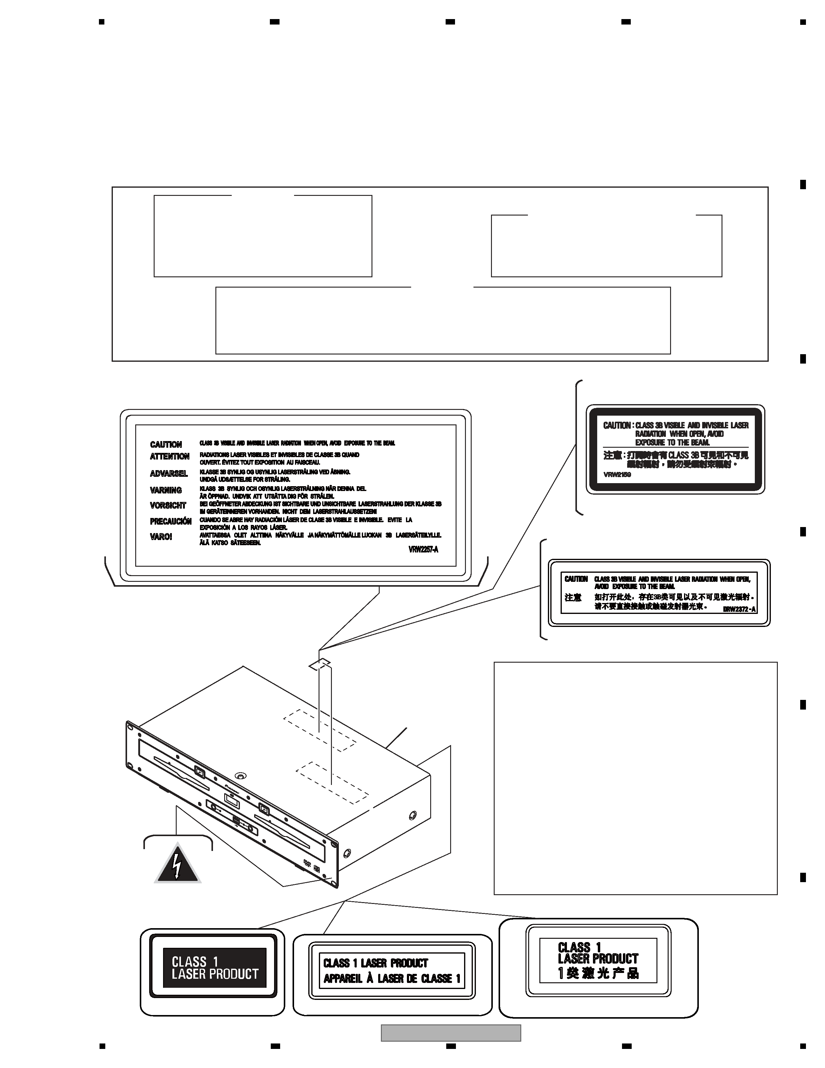
Additional Laser Caution
For TLFXJ
For WYXJ5 and KUCXJ
For WAXJ5
For TLFXJ
(VRW2257)
(DRW1975)
(VRW2159)
For WAXJ5
(DRW2372)
LASER DIODE CHARACTERISTICS
FOR DVD : MAXIMUM OUTPUT POWER : 5 mW
WAVELENGTH : 650 nm
FOR CD :
MAXIMUM OUTPUT POWER : 7 mW
WAVELENGTH : 780 nm
: See page 160, 161, 164, 165.
1. Laser Interlock Mechanism
The position of the switch (S4400,S4500) for detecting loading
completion is detected by the system microprocessor, and the
design prevents laser diode oscillation when the switch is not
in LPS1 terminal side (when the mechanism is not clamped
and LPS1 signal is high level.)
Thus, the interlock will no longer function if the switch is
deliberately set to LPS1 terminal side. (if LPS1 signal is low
level ).
In the SERVICE MODE
the interlock mechanism will not
function.
Laser diode oscillation will continue, if pin 3 (pin 5) of
AN22022A (IC102, IC902) on the SRV1,SRV2 Assy is
connected to GND, or else the terminals of Q102
(Q103), Q902(Q903) are shorted to each other (fault
condition).
2. When the cover is opened, close viewing of the objective lens
with the naked eye will cause exposure to a Class 1 laser
beam.
WARNING !
THE AEL (ACCESSIBLE EMISSION LEVEL) OF THE LASER POWER OUTPUT IS LESS THAN CLASS 1
BUT THE LASER COMPONENT IS CAPABLE OF EMITTING RADIATION EXCEEDING THE LIMIT FOR
CLASS 1.
A SPECIALLY INSTRUCTED PERSON SHOULD DO SERVICING OPERATION OF THE APPARATUS.
For WYXJ5 and KUCXJ
Rear Panel
LABEL CHECK
Printed on the Rear Panel
Printed on the Rear Panel
Printed on the Rear panel
For KUCXJ type Only
EJEC
T
PO
WER
ST
OP
ST
OP
REA
R
DI
SC
1
US
B
1
US
B
2
DI
SC
2
EJEC
T
MEP-700
0
MU
LTI
ENTE
RTAINMENT
PL
AYE
R
This product contains mercury. Disposal of this material may be regulated due to environmental
considerations. For disposal or recycling information, please contact your local authorities or the
Electronics Industries Alliance: www.eiae.org.
The backlighting lamp of LCD in this equipment contains mercury. Disposal of this material may
be regulated due to environmental considerations according to Local, State or Federal Laws.
For disposal or recycling information, please contact your local authorities or the Electronics
Industries Alliance: www.eiae.org
4
MEP-7000
1
2
3
4
A
B
C
D
E
F
1
2
3
4
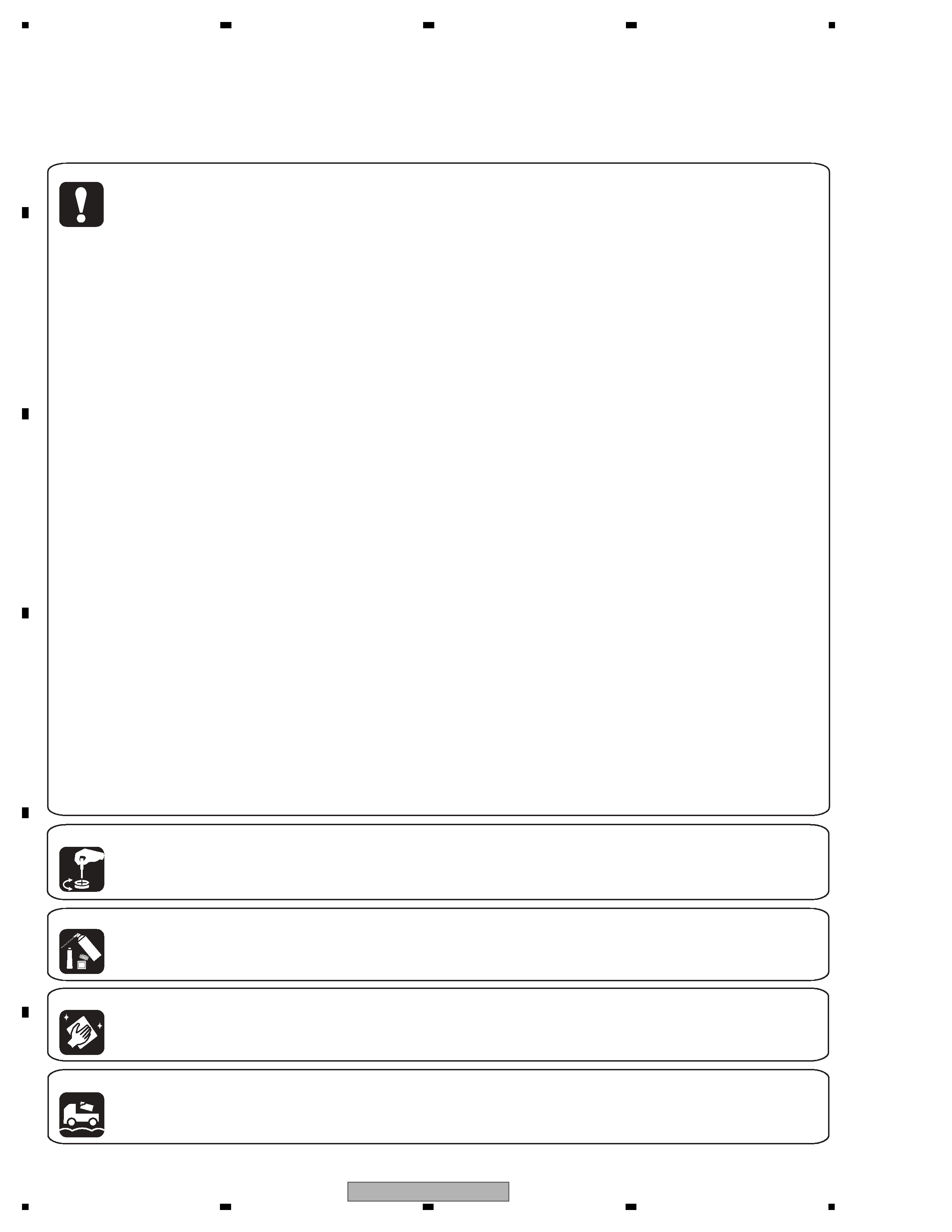
[Important Check Points for Good Servicing]
In this manual, procedures that must be performed during repairs are marked with the below symbol.
Please be sure to confirm and follow these procedures.
1. Product safety
Please conform to product regulations (such as safety and radiation regulations), and maintain a safe servicing environment by
following the safety instructions described in this manual.
1 Use specified parts for repair.
Use genuine parts. Be sure to use important parts for safety.
2 Do not perform modifications without proper instructions.
Please follow the specified safety methods when modification(addition/change of parts) is required due to interferences such as
radio/TV interference and foreign noise.
3 Make sure the soldering of repaired locations is properly performed.
When you solder while repairing, please be sure that there are no cold solder and other debris.
Soldering should be finished with the proper quantity. (Refer to the example)
4 Make sure the screws are tightly fastened.
Please be sure that all screws are fastened, and that there are no loose screws.
5 Make sure each connectors are correctly inserted.
Please be sure that all connectors are inserted, and that there are no imperfect insertion.
6 Make sure the wiring cables are set to their original state.
Please replace the wiring and cables to the original state after repairs.
In addition, be sure that there are no pinched wires, etc.
7 Make sure screws and soldering scraps do not remain inside the product.
Please check that neither solder debris nor screws remain inside the product.
8 There should be no semi-broken wires, scratches, melting, etc.on the coating of the power cord.
Damaged power cords may lead to fire accidents, so please be sure that there are no damages.
If you find a damaged power cord, please exchange it with a suitable one.
9 There should be no spark traces or similar marks on the power plug.
When spark traces or similar marks are found on the power supply plug, please check the connection and advise on secure
connections and suitable usage. Please exchange the power cord if necessary.
a Safe environment should be secured during servicing.
When you perform repairs, please pay attention to static electricity, furniture, household articles, etc. in order to prevent injuries.
Please pay attention to your surroundings and repair safely.
2. Adjustments
To keep the original performance of the products, optimum adjustments and confirmation of characteristics within specification.
Adjustments should be performed in accordance with the procedures/instructions described in this manual.
4. Cleaning
For parts that require cleaning, such as optical pickups, tape deck heads, lenses and mirrors used in projection monitors, proper
cleaning should be performed to restore their performances.
3. Lubricants, Glues, and Replacement parts
Use grease and adhesives that are equal to the specified substance.
Make sure the proper amount is applied.
5. Shipping mode and Shipping screws
To protect products from damages or failures during transit, the shipping mode should be set or the shipping screws should be
installed before shipment. Please be sure to follow this method especially if it is specified in this manual.

5
MEP-7000
5
6
7
8
5
6
7
8
A
B
C
D
E
F
CONTENTS
SAFETY INFORMATION.......................................................................................................................................................... 2
1. SERVICE PRECAUTIONS .................................................................................................................................................... 7
1.1 NOTES ON SOLDERING ............................................................................................................................................... 7
1.2 BACKUP AND RESTORING OF USER DATA................................................................................................................ 7
1.3 NOTE ON ENTRAPMENT OF DIRT IN THE DISPLAY PANEL ..................................................................................... 8
1.4 REPAIR OF THE SJACK ASSY...................................................................................................................................... 8
1.5 CABLE DRESSING OF THE DRIVE UNIT..................................................................................................................... 9
1.6 REASSEMBLING OF THE CONTROL UNIT ............................................................................................................... 14
2. SPECIFICATIONS............................................................................................................................................................... 18
2.1 ACCESSORIES ............................................................................................................................................................ 18
2.2 SPECIFICATIONS ........................................................................................................................................................ 19
2.3 REGARDING PLAYABLE DISCE AND FILES.............................................................................................................. 21
2.4 PANEL FACILITIES....................................................................................................................................................... 25
3. BASIC ITEMS FOR SERVICE ............................................................................................................................................ 29
3.1 CHECK POINTS AFTER SERVICING ......................................................................................................................... 29
3.2 PCB LOCATIONS ......................................................................................................................................................... 30
3.3 JIGS LIST ..................................................................................................................................................................... 32
4. BLOCK DIAGRAM .............................................................................................................................................................. 34
4.1 OVERALL WIRING (CONTROL UNIT)......................................................................................................................... 34
4.2 OVERALL WIRING (DRIVE UNIT) ............................................................................................................................... 36
4.3 BLOCK DIAGRAM ........................................................................................................................................................ 38
5. DIAGNOSIS ........................................................................................................................................................................ 48
5.1 POWER ON SEQUENCE............................................................................................................................................. 48
5.2 CONFIRMATION OF COMMUNICATION WITH THE PC VIA USB ............................................................................. 55
5.3 TROUBLE SHOOTING................................................................................................................................................. 56
5.4 DEFECT JUDGMENT OF THE PICKUP ASSY ........................................................................................................... 85
6. SERVICE MODE ................................................................................................................................................................. 86
6.1 TABLE OF CONTENTS ................................................................................................................................................ 86
6.2 SERVICE MODE FOR THE DRIVE UNIT .................................................................................................................... 87
6.3 SERVICE MODE FOR THE CONTROL UNIT.............................................................................................................. 97
6.4 ERROR CODE LIST ................................................................................................................................................... 103
6.5 STATUS LEDS ............................................................................................................................................................ 104
7. DISASSEMBLY ................................................................................................................................................................. 108
7.1 DRIVE UNIT ............................................................................................................................................................... 108
7.2 CONTROL UNIT ......................................................................................................................................................... 113
8. EACH SETTING AND ADJUSTMENT .............................................................................................................................. 115
8.1 CONFIRMATION MODE AND ADJUSTMENT METHOD FOR LOAD ON THE JOG DIAL ....................................... 115
8.2 RESET OF DVD/CD DRIVE DATA.............................................................................................................................. 116
8.3 UPDATING/RECOVERY OF FIRMWARE................................................................................................................... 117
8.4 MANUAL INPUT OF DVD/CD DRIVE DATA ............................................................................................................... 132
9. EXPLODED VIEWS AND PARTS LIST............................................................................................................................. 134
9.1 PACKING SECTION ................................................................................................................................................... 134
: DRIVE UNIT
9.2 EXTERIOR SECTION ................................................................................................................................................ 136
9.3 FRONT PANEL SECTION .......................................................................................................................................... 138
9.4 SLOT-IN MECHA SECTION ....................................................................................................................................... 140
: CONTROL UNIT
9.5 EXTERIOR SECTION ................................................................................................................................................ 142
9.6 CONTROL PANEL SECTION ..................................................................................................................................... 144
10. SCHEMATIC DIAGRAM .................................................................................................................................................. 146
: DRIVE UNIT
10.1 SMAIN ASSY (1/5) ................................................................................................................................................... 146
10.2 SMAIN ASSY (2/5) ................................................................................................................................................... 148
10.3 SMAIN ASSY (3/5) ................................................................................................................................................... 150
10.4 SMAIN ASSY (4/5) ................................................................................................................................................... 152
10.5 SMAIN ASSY (5/5) ................................................................................................................................................... 154
10.6 EJTB ASSY .............................................................................................................................................................. 156
10.7 FSWB ASSY ............................................................................................................................................................. 157
10.8 SJACK ASSY............................................................................................................................................................ 158
10.9 SRV1 ASSY .............................................................................................................................................................. 160
10.10 SLMB1 ASSY ......................................................................................................................................................... 162
10.11 USBB ASSY ........................................................................................................................................................... 163
10.12 SRV2 ASSY ............................................................................................................................................................ 164
10.13 SLMB2 ASSY ......................................................................................................................................................... 166
10.14 ACIN ASSY............................................................................................................................................................. 167