ORDER NO.
PIONEER CORPORATION 4-1, Meguro 1-chome, Meguro-ku, Tokyo 153-8654, Japan
PIONEER ELECTRONICS (USA) INC. P.O. Box 1760, Long Beach, CA 90801-1760, U.S.A.
PIONEER EUROPE NV Haven 1087, Keetberglaan 1, 9120 Melsele, Belgium
PIONEER ELECTRONICS ASIACENTRE PTE. LTD. 253 Alexandra Road, #04-01, Singapore 159936
PIONEER CORPORATION 2008
S-DV3SW
RRV3747
T-ZZR MAY 2008 Printerd in Japan
SPEAKER SYSTEM
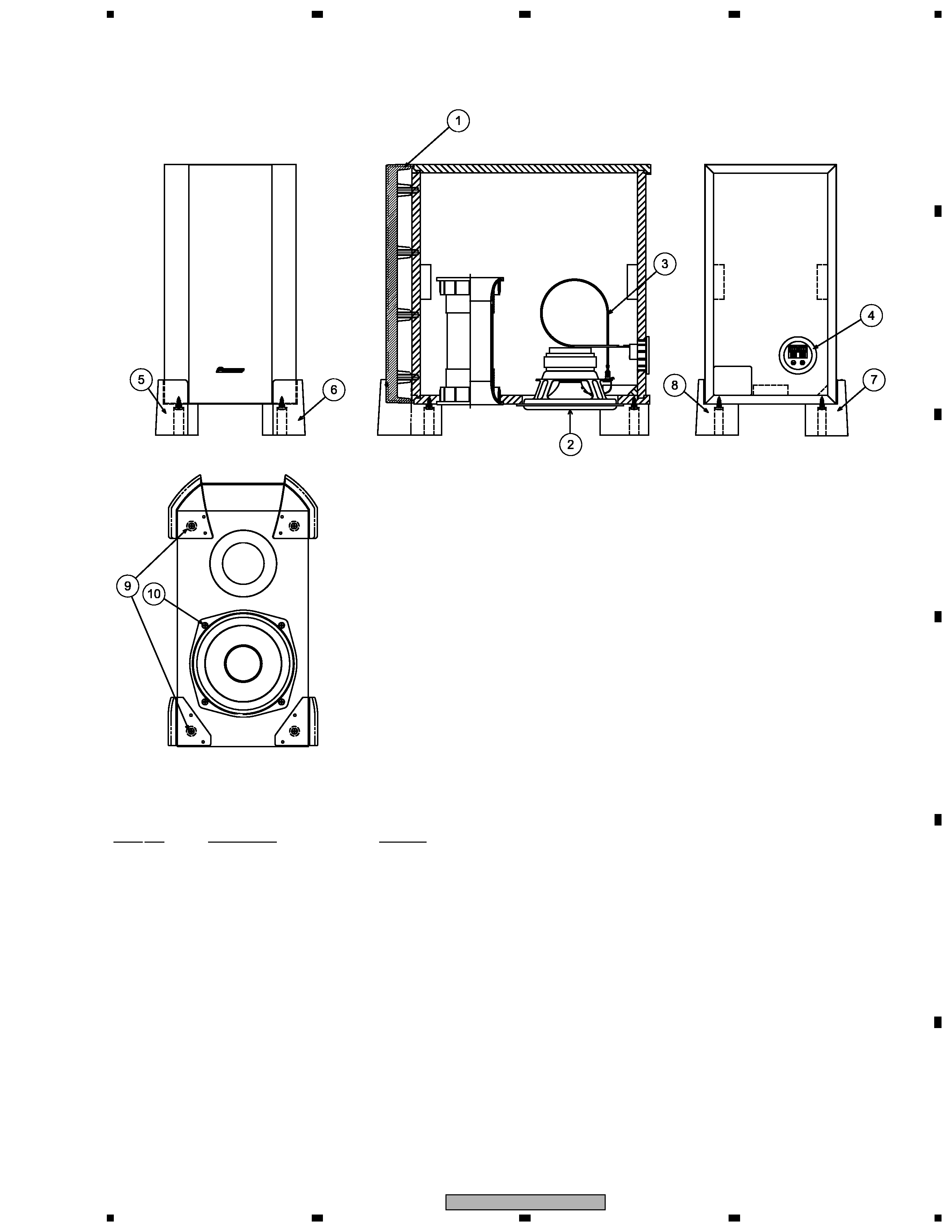
1. REASSEMBLY AND DISASSEMBLY PRECAUTIONS
The speaker unit is attached to the bottom by 4 external screws.
To detach it, unfasten those screws. When attaching it, face its
terminal backward.
The cosmetic baffle assy is attached to the baffle board by
press-fitting. To detach it, pry it open by inserting a flat blade
screwdriver into lower slot.
S-DV3SW
XTW/E
S-DV3SW
XTW/NC
2
S-DV3SW
1
2
3
4
C
D
F
A
B
E
1
2
3
4
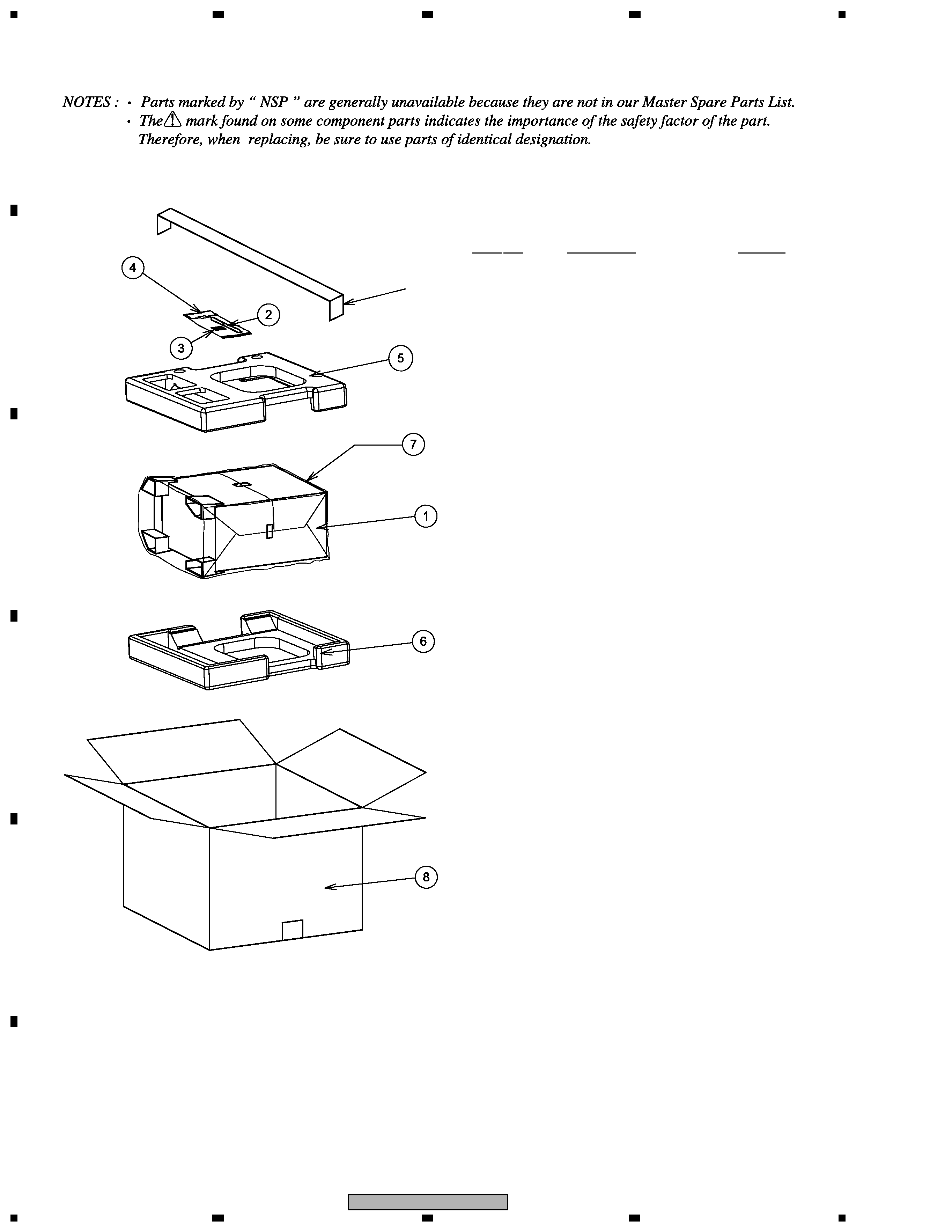
2. EXPLODED VIEWS AND PARTS LIST
2.1 PACKING
Tape
NSP 1
CS Assy (SW)
SMW6266
2
Speaker Cord (Purple)
SDS1179
3
Non Skid Pads
SEP6031
4
Polyethylene Bag S1
SHL1352
5
Protector (Top)
SHA6171
6
Protector (Bottom)
SHA6172
7
Protection Sheet S6
SHC1825
8
Packing Case
(for XTW/E type)
SHG6343
(for XTW/NC type)
SHG6348
PACKING Parts List
Mark No.
Description
Part No.
3
S-DV3SW
5
6
7
8
5
6
7
8
C
D
F
A
B
E
2.2 CS Assy (SW)
(×4)
(×4)
1
Cosmetic Buffle Assy
SXB6016
2
Speaker
A14LR80-53C
3
Cable
SDD6008
4
Input Terminal
SKX1060
5
Front Base (L)
SNK6196
6
Front Base (R)
SNK6198
7
Rear Base (L)
SNK6200
8
Rear Base (R)
SNK6202
9
Screw
BYC40P200FNI
10
Screw
BYC40P160FTC
CS Assy (SW) Parts List
Mark No.
Description
Part No.
4
S-DV3SW
1
2
3
4
C
D
F
A
B
E
1
2
3
4
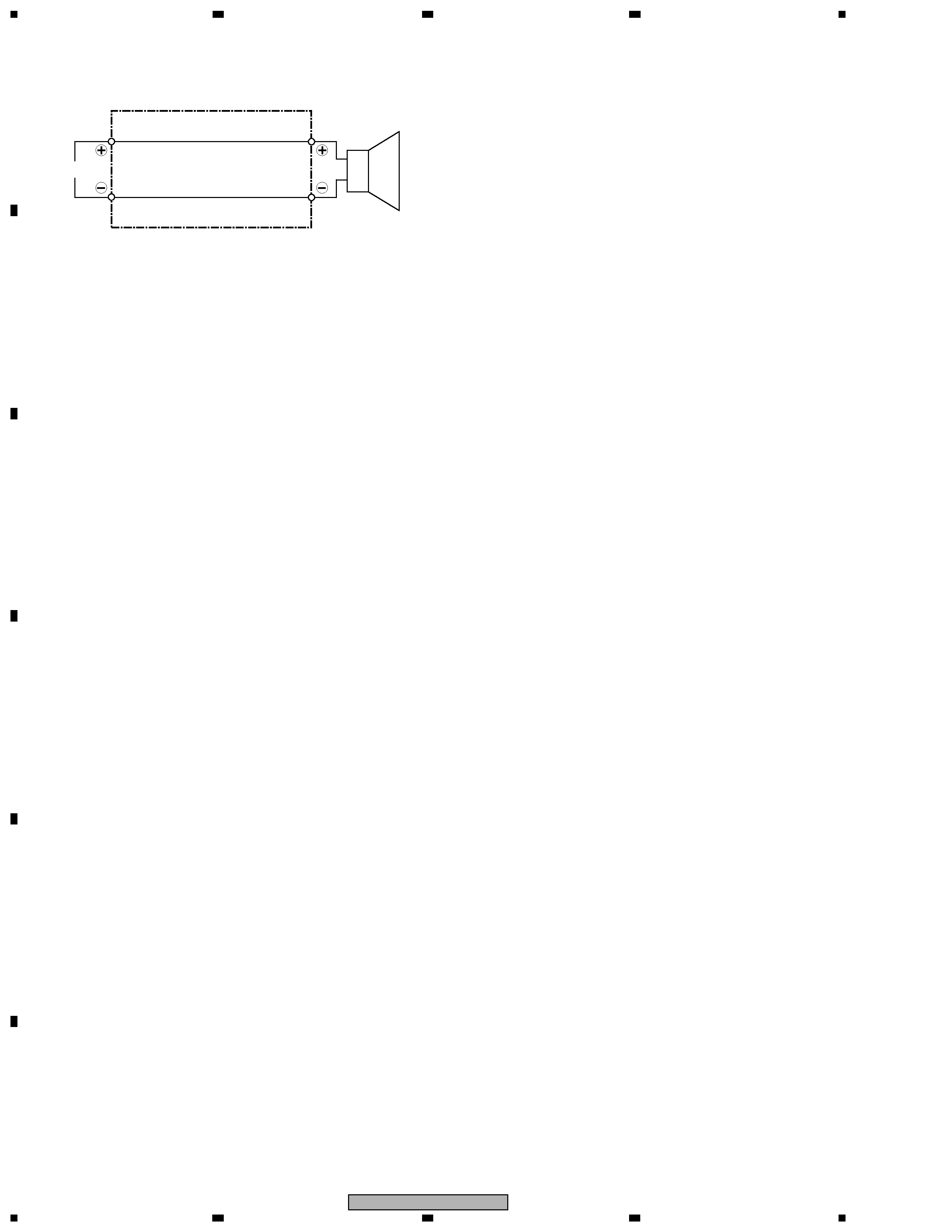
3. SCHEMATIC DIAGRAM
INPUT
Speaker
Black
Red
Cable (SDD6008)