ORDER NO.
PIONEER CORPORATION 4-1, Meguro 1-chome, Meguro-ku, Tokyo 153-8654, Japan
PIONEER ELECTRONICS (USA) INC. P.O. Box 1760, Long Beach, CA 90801-1760, U.S.A.
PIONEER EUROPE NV Haven 1087, Keetberglaan 1, 9120 Melsele, Belgium
PIONEER ELECTRONICS ASIACENTRE PTE. LTD. 253 Alexandra Road, #04-01, Singapore 159936
PIONEER CORPORATION 2007
Center
Surround
Front
S-DV262T
RRV3582
SPEAKER SYSTEM
S-DV262T
XJC/E, XJC/NC
T-ZZR MAY 2007 Printed in Japan
S-DV262T
2
12
3
4
12
3
4
C
D
F
A
B
E
1. REASSEMBLY AND DISASSEMBLY PRECAUTIONS
Rear
Front
Stem
(the bottom of cabinet)
Speaker Stand Base
GRILLE
The grille is attached to the cabinet by its bosses applied with
adhesive. To detach it, pry it open by inserting a flat blade
screwdriver into lower right and lower left slot. To attach it,
apply adhesive to the holes on the baffle. Then press it to the
baffle.
CAUTION
There are 10 bosses for press-fitting at the grille. To detach the
grille, remove in order from lower bosses. (Refer to the figure
in page 4.) In order not to damage the bosses, don't remove it
forcibly. Pry it open little by little. Be sure to insert a flat blade
screwdriver from just beside of its bosses.
WOOFER
The woofer is attached to the baffle by 4 external screws.
To detach it, unfasten those screws. To detach it, first remove
the grille. Then remove the screws. When attaching it, face its
terminal downward.
TWEETER
The tweeter is attached to the baffle by 3 external screws. To
detach it, unfasten those screws. To detach it, first remove the
grille. Then remove the screws. When attaching it, face its ter-
minal leftward and rightward.
COSMETIC PANEL
The cosmetic panel is attached to the baffle by its bosses. To
detach it, pry it open by inserting a flat blade screwdriver into
lower slot. To detach it, first remove the speaker stand base and
grille. Then remove the cosmetic panel. When attaching it, fit
the boss into the hole on the baffle.
GRILLE
The grille assy is attached to the cabinet by 8 external screws.
To detach it ,unfasten those screws.
SPEAKER UNIT
The speaker unit, together with the grille assy, is attached to the
cabinet by 4 external screws. To detach it, first remove the
grille assy. Next remove the cabinet. Then removethe cable.
When attaching it, face its terminal toward the input terminal.
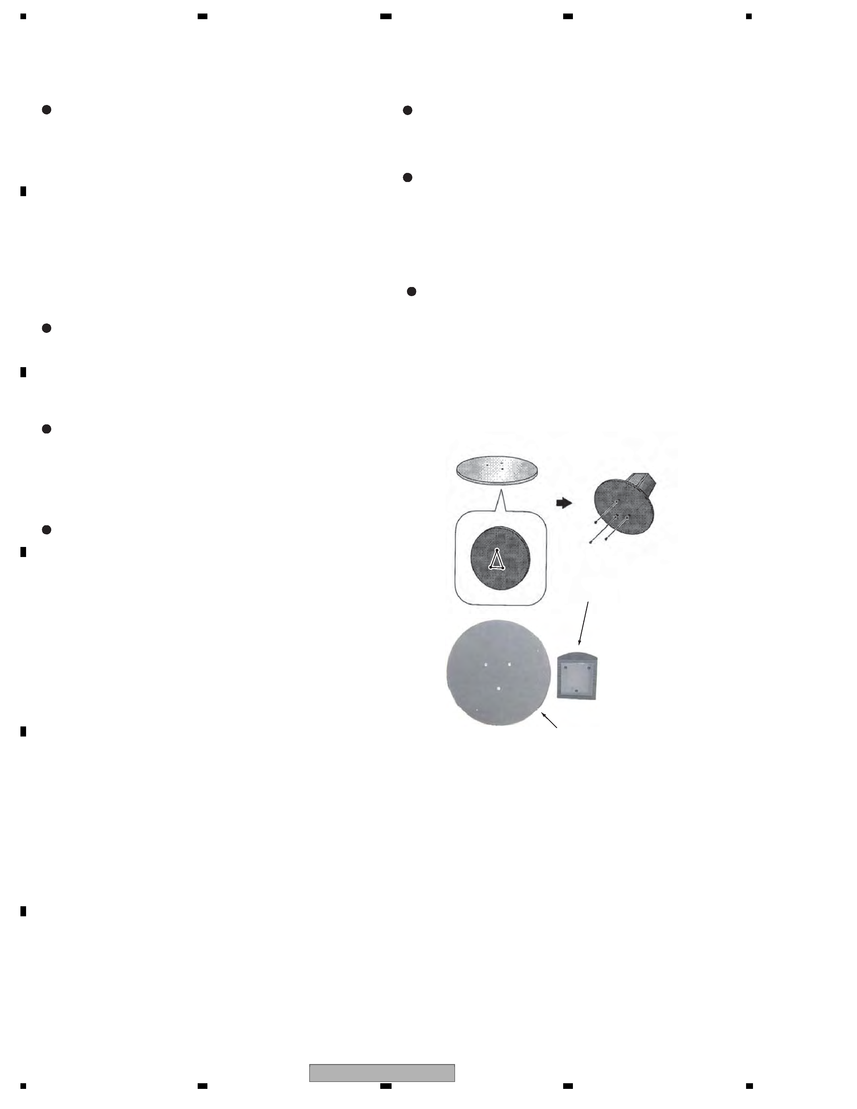
SPEAKER STAND BASES
The speaker stand base is attached to the bottom of cabinet by 3
external screws. To detach it, unfasten those screws.Attach the
speaker stand bases to the stems using the screws provided.
Once you have aligned the stem and base, secure with the small
screws at the points shown below. Note that the speaker should
face in the direction of the base of the isosceles triangle (out-
lined below).
1.1 FRONT, SURROUND SPEAKER
1.2 CENTER SPEAKER
S-DV262T
3
5
678
56
7
8
C
D
F
A
B
E
2. EXPLODED VIEWS AND PARTS LIST
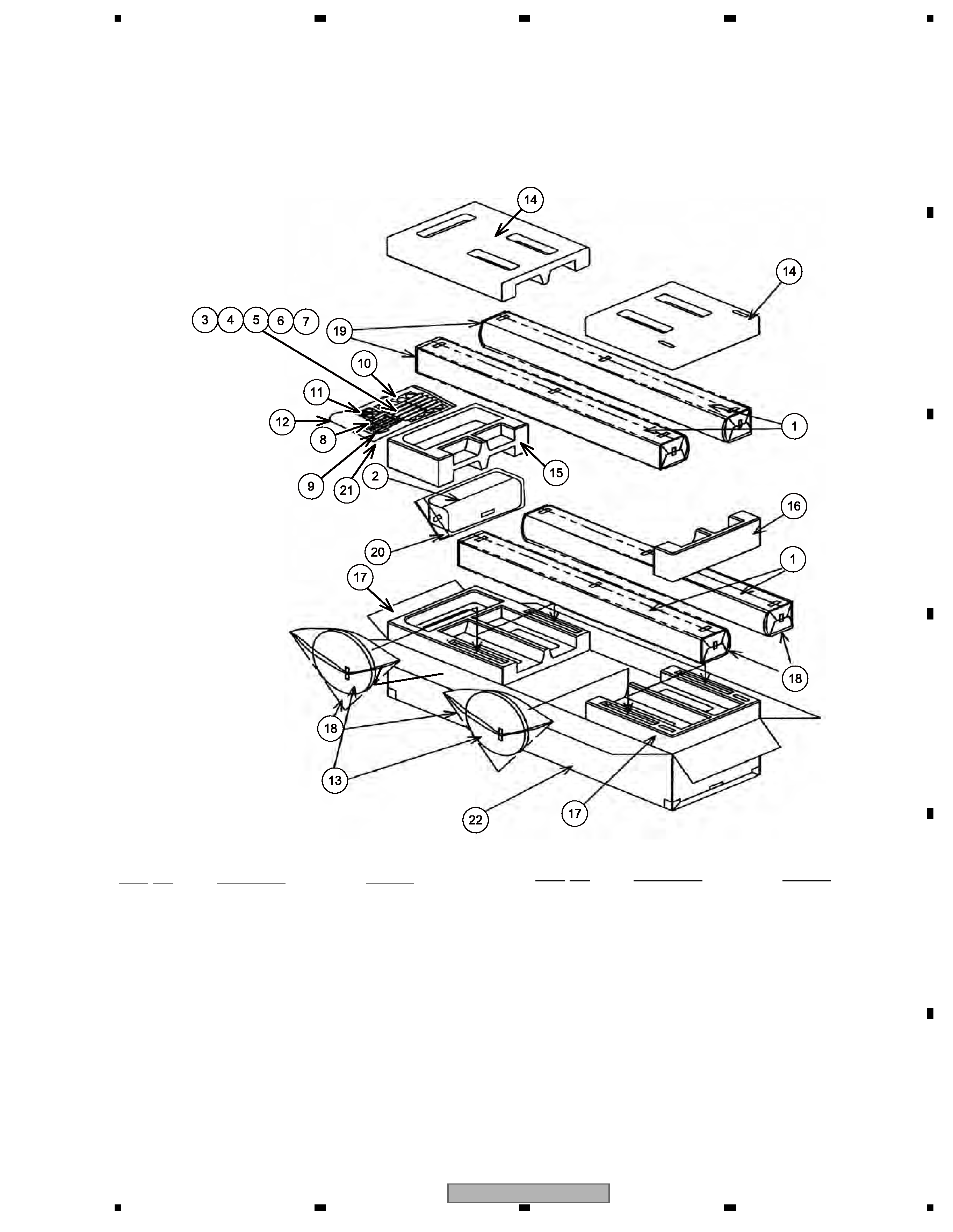
2.1 PACKING
PACKING Parts List
NOTES : · Parts marked by " NSP " are generally unavailable because they are not in our Master Spare Parts List.
· The
> mark found on some component parts indicates the importance of the safety factor of the part.
Therefore, when replacing, be sure to use parts of identical designation.
8
1
8
10
4
7
9
2
Mark No.
Description
Part No.
NSP 1
CS Assy(Front, Surround )
SMW6229
NSP 2
CS Assy (Center )
SMW6226
3
Speaker Cord (FL: White)
SDS1174
4
Speaker Cord (FR: Red)
SDS1175
5
Speaker Cord (SL: Blue)
SDS1176
6
Speaker Cord (SR: Gray)
SDS1177
7
Speaker Cord (C: Green)
SDS1178
8
Screw
CYC40P300FTC
(for Speaker Stand Base)
9
Polyethylene Bag S0
SHL1314
10
Large Non Skid Pad
SEP6014
11
Polyethylene Bag S2
SHL1251
12
Polyethylene Bag S2
SHL1417
13
Speaker Stand Base
SMS6031
14
Protector
SHA6140
15
Protector (Middle)
SHA6141
16
Protector (Middle)
SHA6142
17
Protector (Down)
SHA6143
18
Protection Sheet
SHC6051
19
. . . .
20
Polyethylene Bag S3
SHL1427
21
Polyethylene Bag S2
SHL6078
22
Packing Case (for XJC/E)
SHG6261
22
Packing Case (for XJC/NC)
SHG6296
Mark No.
Description
Part No.
S-DV262T
4
12
3
4
12
3
4
C
D
F
A
B
E
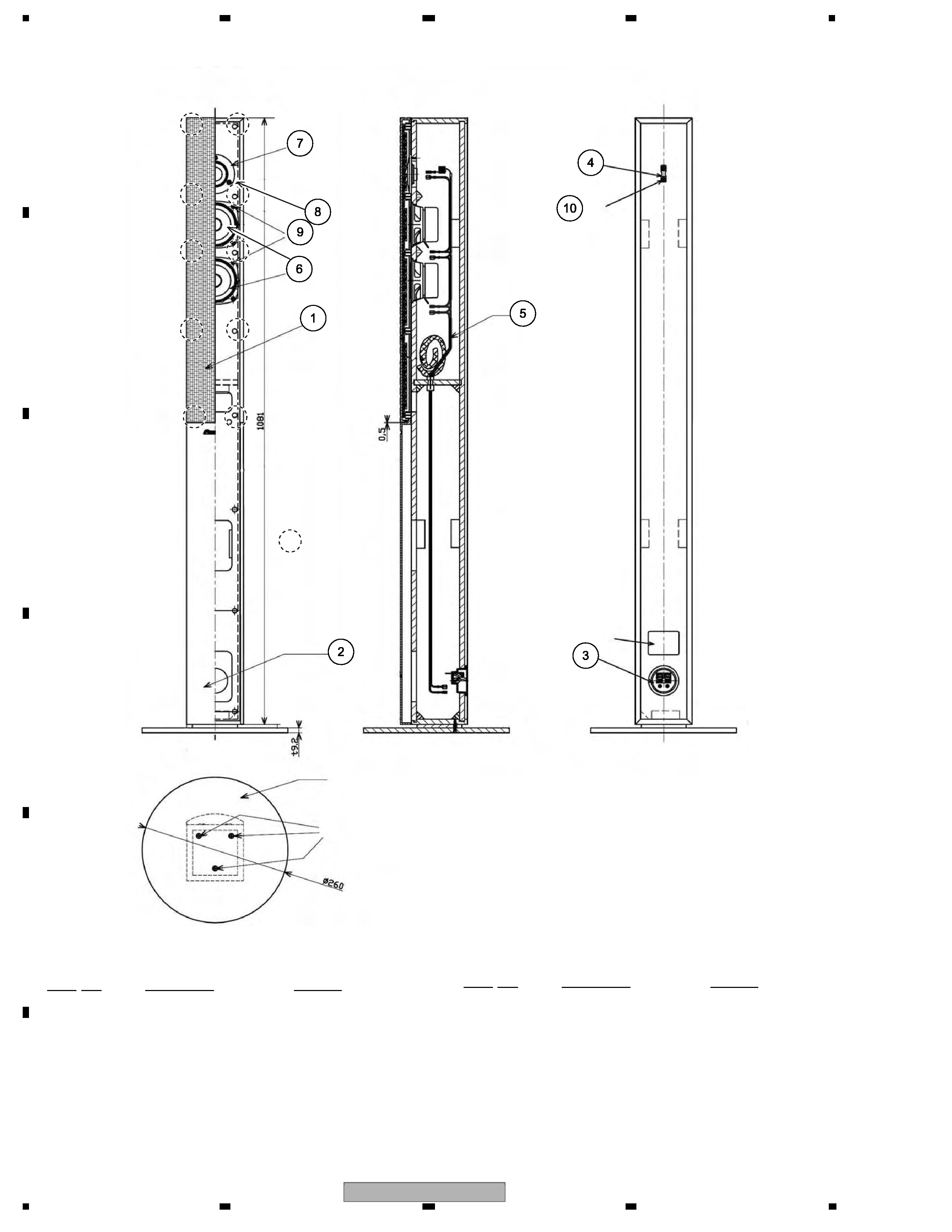
2.2 SPEAKER SYSTEM (FRONT, SURROUND)
SPEAKER SYSTEM (FRONT, SURROUND) Parts List
5
10
11 (x3)
12 (x8)
2
6
9
3
4
Model Label
Speaker Stand Base
( refer to 2.1 PACKING
/ No.13 )
Screw
( refer to 2.1 PACKING
/ No.8 Screw )
12 (x2)
: the bosses of
the grille
Mark No.
Description
Part No.
1
Grille
SMG6122
2
Cosmetic Plate Assy
SXB6007
3
Input Terminal
SKX1060
4
Fastener
SNB6003
5
Network Assy
SWN6020
6
Speaker (Woofer)
K77DC55-51F
7
Speaker (Tweeter)
FK26AP32-51F
8
Screw (for Tweeter)
BYC35P160FTC
9
Screw (for Woofer)
BYC35P120FTC
10
Screw (for Fastener)
BYC35P120FTB
Mark No.
Description
Part No.
S-DV262T
5
5
678
56
7
8
C
D
F
A
B
E
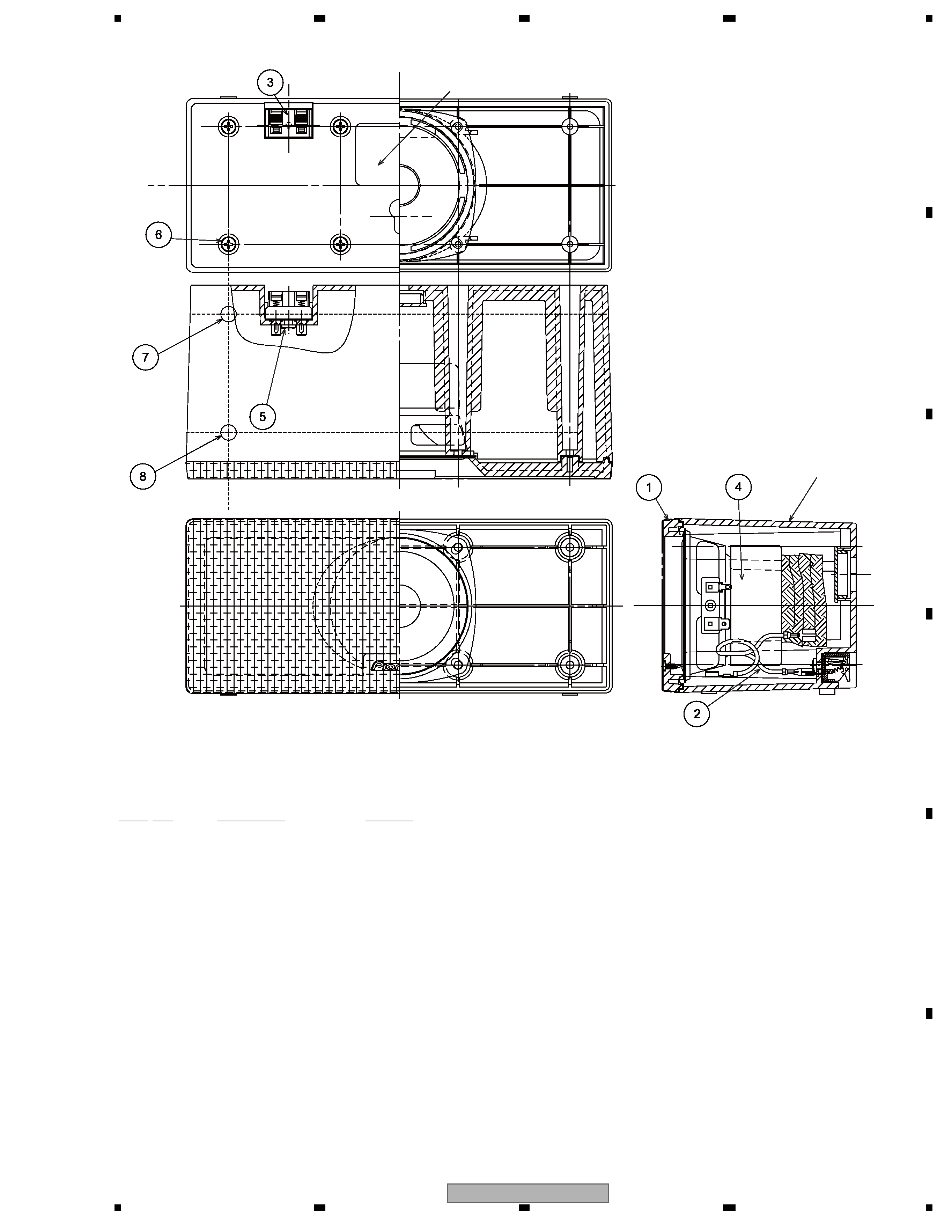
2.3 SPEAKER SYSTEM (CENTER)
SPEAKER SYSTEM (CENTER) Parts List
Cabinet
5
8
2
Model Label
10
(x8)
4
9
11
12
Mark No.
Description
Part No.
1
Grille Assy
SMG6129
2
Connecting Cord
SDD1345
3
Input Terminal
SKX6034
4
Speaker
K77DR55-52C
5
Screw (for Input Terminal)
BPZ35P080FTC
6
Screw (for Cabinet)
BPZ35P110FTB
7
Non Skid Pads
SEP1263
8
Non Skid Pads
SEP6028