ORDER NO.
PIONEER CORPORATION 4-1, Meguro 1-chome, Meguro-ku, Tokyo 153-8654, Japan
PIONEER ELECTRONICS (USA) INC. P.O. Box 1760, Long Beach, CA 90801-1760, U.S.A.
PIONEER EUROPE NV Haven 1087, Keetberglaan 1, 9120 Melsele, Belgium
PIONEER ELECTRONICS ASIACENTRE PTE. LTD. 253 Alexandra Road, #04-01, Singapore 159936
PIONEER CORPORATION 2007
S-DV262SW
RRV3656
SPEAKER SYSTEM
S-DV262SW
XCN5
1. REASSEMBLY AND DISASSEMBLY PRECAUTIONS
1.1 SUBWOOFER
The speaker unit is attached to the back board by 4 external
screws. To detach it, unfasten those screws. When attaching it,
face its terminal back board.
The cosmetic baffle assy is attached to the baffle board by
press-fitting. To detach it, pry it open by inserting a flat blade
screwdriver into lower slot.
T-ZZR JULY 2007 Printed in Japan
S-DV262SW
2
12
3
4
12
3
4
C
D
F
A
B
E
2. EXPLODED VIEWS AND PARTS LIST
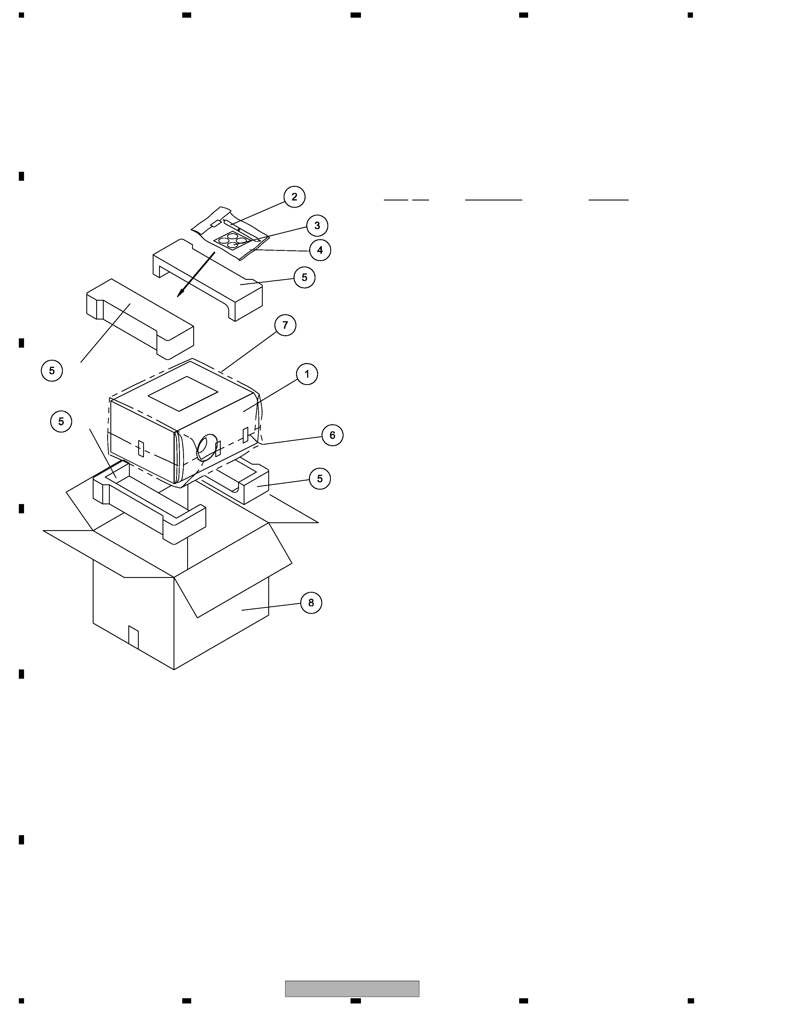
2.1 PACKING
PACKING Parts List
NOTES :
· Parts marked by " NSP " are generally unavailable because they are not in our Master Spare Parts List.
· The
> mark found on some component parts indicates the importance of the safety factor of the part.
Therefore, when replacing, be sure to use parts of identical designation.
4 (2/2)
6
5
2
2
4 (2/2)
4 (1/2)
4 (1/2)
1
3
Mark No.
Description
Part No.
NSP 1
CS ASSY (SW)
SMW6251
2
Speaker Cord (Purple)
SDS1179
3
Non Skid Pad
SEC2070
4
Polyethylene Bag S1
SHL1352
5
Protector
SHA6114
6
Protection Sheet
SHC1821
7
Polyethylene Bag
SHL6079
8
Packing Case
SHG6308
S-DV262SW
3
56
7
8
56
7
8
C
D
F
A
B
E
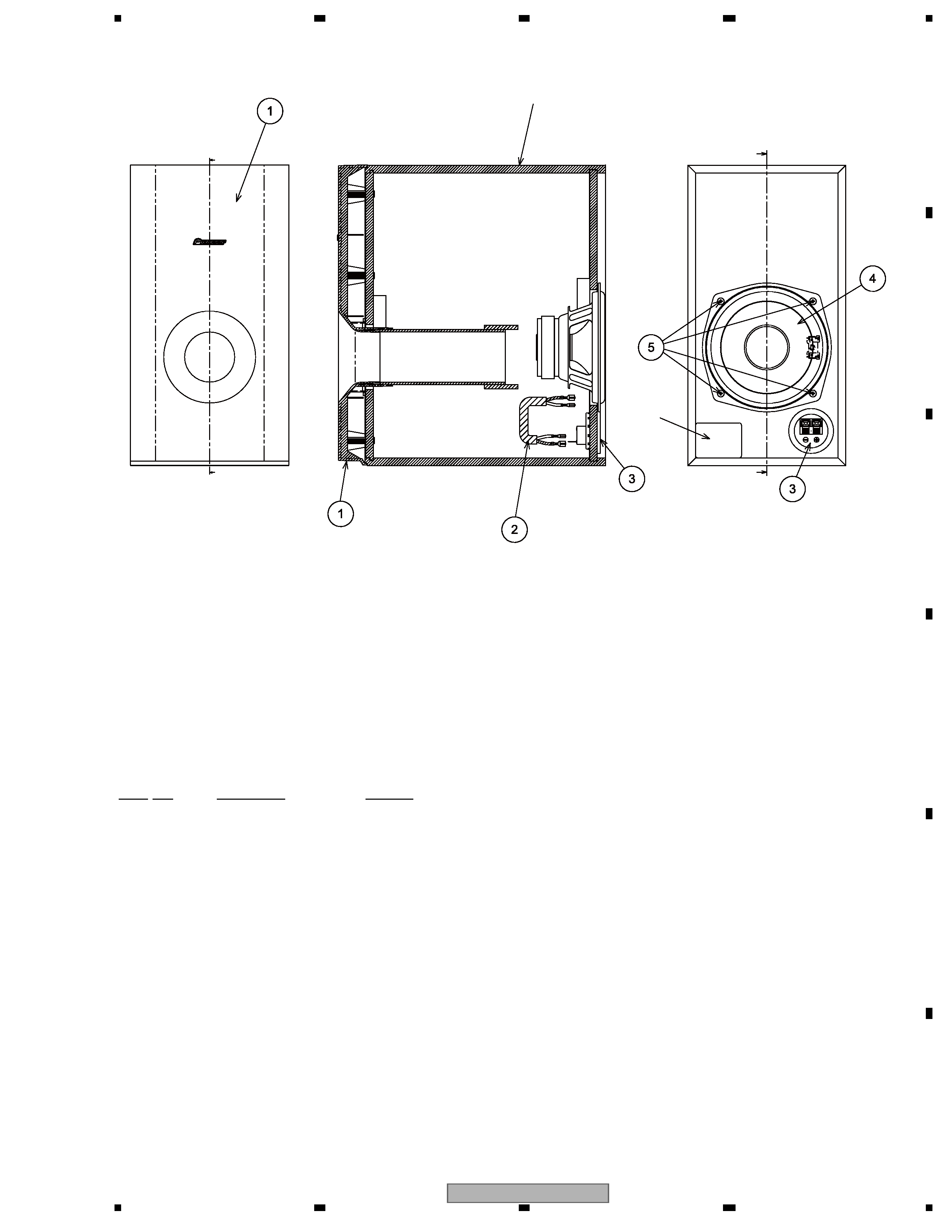
2.2 SPEAKER SYSTEM
SPEAKER SYSTEM Parts List
7
Model Label
11
10
Cabinet
2
8
9
9
Mark No.
Description
Part No.
1
Cosmetic BF. Assy
SXB6008
2
Connecting Cord
SDD1350
3
Input Terminal
SKX1060
4
Speaker
A14LU80-52C
5
Screw (for Speaker)
BYC40P130FTB
S-DV262SW
4
12
3
4
12
3
4
C
D
F
A
B
E
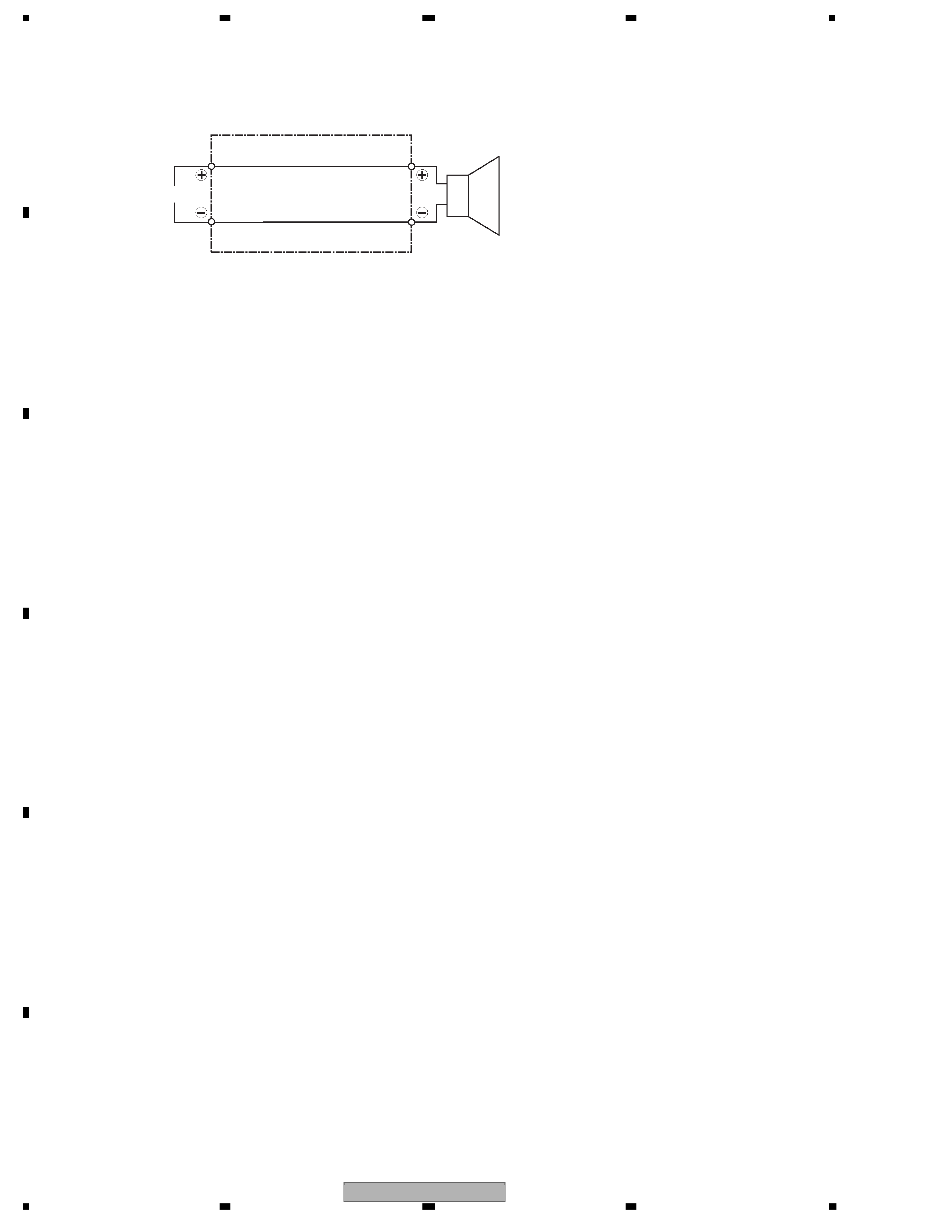
3. SCHEMATIC DIAGRAM
INPUT
Speaker
Black
Red
Connecting Cord (SDD1350)