ORDER NO.
PIONEER CORPORATION 4-1, Meguro 1-chome, Meguro-ku, Tokyo 153-8654, Japan
PIONEER ELECTRONICS (USA) INC. P.O. Box 1760, Long Beach, CA 90801-1760, U.S.A.
PIONEER EUROPE NV Haven 1087, Keetberglaan 1, 9120 Melsele, Belgium
PIONEER ELECTRONICS ASIACENTRE PTE. LTD. 253 Alexandra Road, #04-01, Singapore 159936
PIONEER CORPORATION 2005
RRV3222
T ZZK SEPT. 2005 Printed in Japan
SPEAKER SYSTEM
S-DV232T
XCN
Front
Sub Woofer
Center
Surround
Component
System
Service Manual
Remarks
5.1CH SURROUND SYSTEM
HTZ-232DV/NAXJ
RRV3213
DVD/CD RECEIVER
XV-DV232T/NAXJ
RRV3211 (RRV3187)
SPEAKER SYSTEM
S-DV232T/XCN
RRV3222
This service manual
This product is component of system.
FOR PRECAUTION OF REASSEMBLY AND DISASSEMBLY
CS Assy ( Subwoofer )
The speaker unit is attached to the rear baffle by 4 external
screws. To detach it, unfasten those screws.
When attaching it, face its terminal rightward.
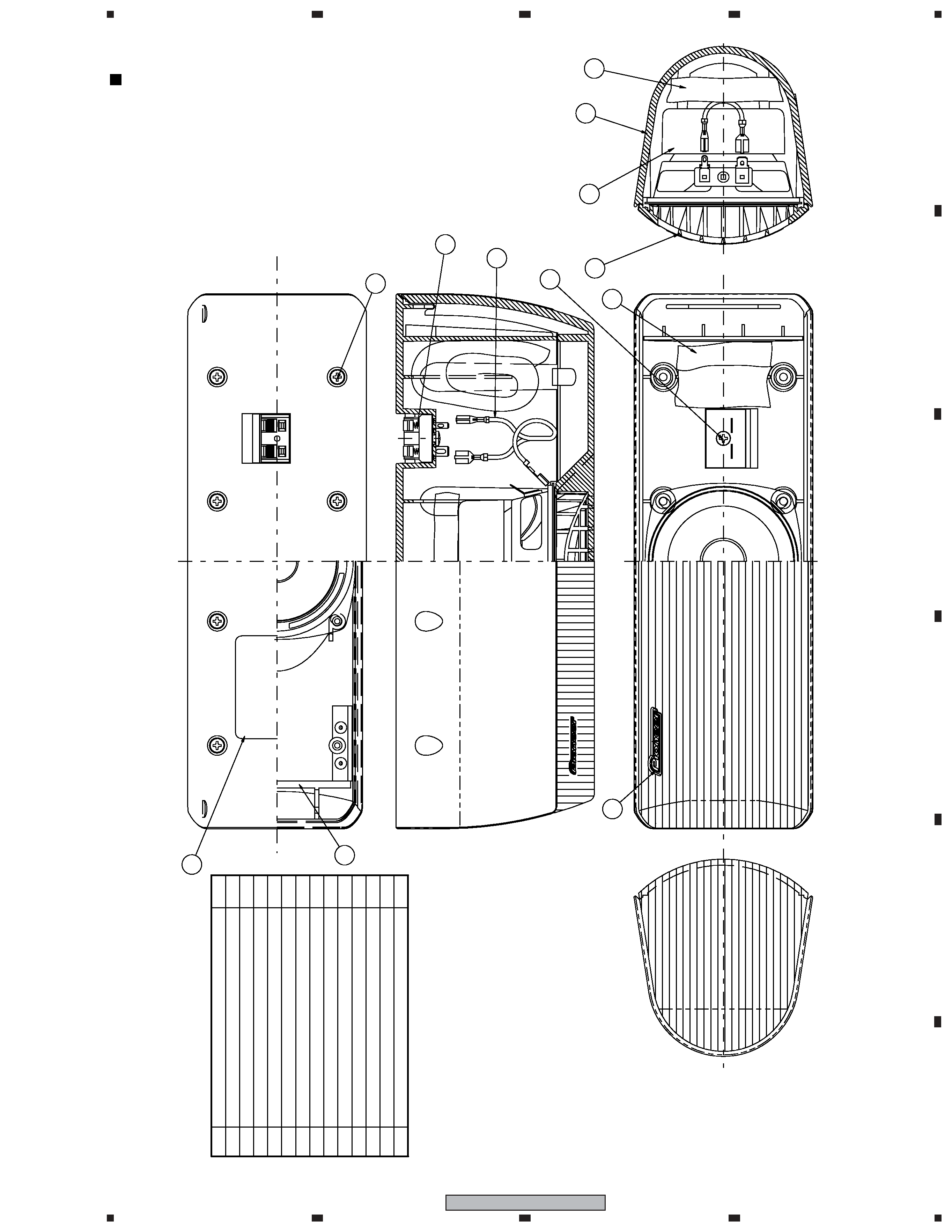
CS Assy ( Front )
The grille assy is attached to the cabinet by 9 external screws.
To detach it, first remove 3 screws of connection part with the
base assy. Next remove 2 screws of the cosmetic plate assy
lower side. Next remove 7 screws of the cabinet. Then carefully
disconnect the wires of the woofer mounted on the grille assy
and input terminal. To detach the cosmetic plate assy, remove 2
screws of connection part with the grille assy.
The woofer is attached to the grille by 4 internal screws. To
detach it, first unfasten those screws. Next remove the cable.
When attaching it, face its terminal upward.
The tweeter is attached to the baffle by adhesives. To exchange
the tweeter, do it with the grille assy.
The cosmetic plate assy is attached to the grille assy by 2 inter-
nal screws. To detach it, first remove the grille assy. Next un-
fasten those screws.
CS Assy ( Surround )
The grille assy is attached to the cabinet by its bosses. To de-
tach it, pry it open by inserting a flat blade screw driver into
lower slot. To attach it, press it to the inner baffle.
The speaker unit is attached to the inner baffle by 4 external
screws. To detach it, first remove the grille assy. Next unfasten
those screws, and remove the cable. When attaching it, face its
terminal downward.
CS Assy ( Center )
The grille assy is attached to the cabinet by 8 external screws.
To detach it ,unfasten those screws.
The speaker unit, together with the grille assy, is attached to the
cabinet by 4 external screws. To detach it, first remove the
grille assy. Next remove the cabinet. Then remove the cable.
When attaching it, face its terminal toward the input terminal.
2
1
23
4
12
3
4
C
D
F
A
B
E
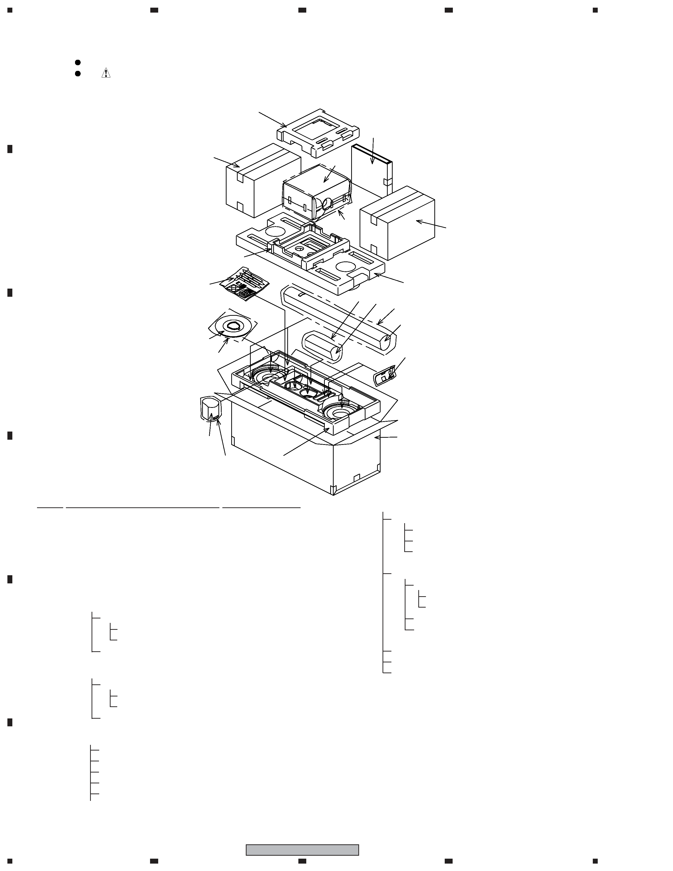
S-DV232T
1
Bottom Protector (ST)
SHA2486
2
Top Protector (ST)
SHA2485
NSP
3
CS Assy (Front)
SMW6170
NSP
4
CS Assy (Center)
SMW6168
NSP
5
CS Assy (Surround)
SMW6167
NSP
6
CS Assy (Subwoofer)
SMW6175
NSP
7
Bracket Set (L)
SEA1695
Bracket (L) Assy
SXG1083
NSP
Bracket (L)
SNK2895
NSP
Packing
SEC1922
Polyethylene Bag S1
SHL1312
NSP
8
Bracket Set (R)
SEA1696
Bracket (R) Assy
SXG1084
NSP
Bracket (R)
SNK2896
NSP
Packing
SEC1922
Polyethylene Bag S1
SHL1312
NSP
9
Accessory Set
SEA1685
Speaker Wire (FL: White)
SDS1174
Speaker Wire (FR: Red)
SDS1175
Speaker Wire (SL: Blue)
SDS1176
Speaker Wire (SR: Gray)
SDS1177
Speaker Wire (C: Green)
SDS1178
NSP
Screw Set
SEA1674
Screw (for Bracket)
BMZ50P120FNC
Screw (for Base)
CMZ50P200FTB
Polyethylene Bag S0
SHL1314
NSP
Bracket Set
SEA1681
NSP
Screw Set
SEA1682
Screw
BMZ50P120FNC
Polyethylene Bag S0 SHL1314
Mounting Bracket
SNN1047
Polyethylene Bag S1
SHL1429
Non Skid Pad
SEC1912
Non Skid Pad
SEP6002
Polyethylene Bag
SHL1251
10 Spacer
SHD1068
11 Polyethylene Bag S2
SHL1426
12 Polyethylene Bag S1
SHL1419
13 Polyethylene Bag S2
SHL1420
14 Polyethylene Bag S3
SHL1427
15 Paking Case
SHG6113
18 Protection Sheet
SHC1821
19 Protector (SW)
SHA2487
20 Protector
SHB1164
For Packing
Parts marked by "NSP" are generally unavailable because they are not in our Master Spare Parts List.
The
mark found on some component parts indicates the importance of the safety factor of the part.
Therefore, when replacing, be sure to use parts of identical designation.
NOTES:
PARTS LIST
Mark No.
Description
Part No.
10
10
6
19
18
19
1
2
3
4
5
Base Assy
7, 8
11
13
12
14
15
9
20
3
1
23
4
1
2
3
4
C
D
F
A
B
E
S-DV232T
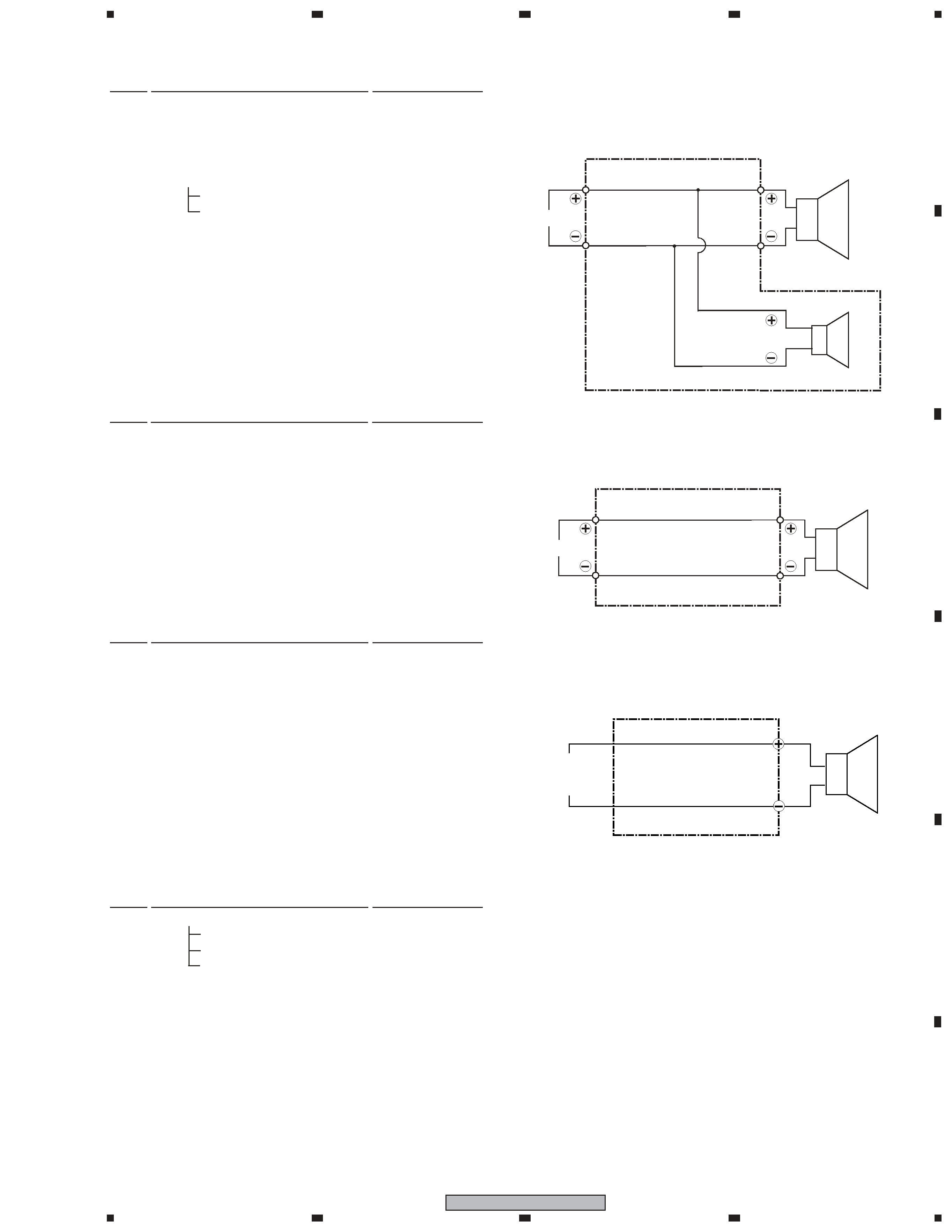
SCHEMATIC DIAGRAM
White with Gray Line
White
Speaker
INPUT PLUG
( Purple )
Connecting Cord (SDD1339)
INPUT
Speaker
White
Red
Connecting Cord (SDD1345)
2. CS Assy (Center, Surround)
3. CS Assy (Subwoofer)
1. CS Assy (Front)
Network Ass'y (SWN1748)
INPUT
Woofer
Tweeter
White
Blue
Red
Blue
Non Skid Pad
SEB1283
Packing
SEC1923
NSP
Network Ass'y
SWN1748
Input Terminal Board
SKX1089
Cosmetic Plate Assy
SXB1476
NSP
Badge 28
SAM1506
NSP
Cosmetic Plate
SNK2856
Speaker (Woofer)
K77DU55-53D
Screw (for Base)
BPZ30P060FNC
Screw
BPZ35P080FNI
(for Woofer, Cosmetic Plate, Input Terminal)
Screw (for Cabinet)
BPZ35P120FNI
CS Assy (Front)
Mark No.
Description
Part No.
CS Assy (Surround)
Grille Ass'y
SMG6077
Connecting Cord
SDD1345
Gasket
SEC1910
Packing (size: 4 x 101 mm)
SEC1927
Packing (size: 4 x 111 mm)
SEC1928
Packing (size: 4 x 84 mm)
SEC1929
Input Terminal Board
SKX1089
Speaker
K77DU55-51D
Screw (for Input Terminal, Speaker)
BPZ35P080FNI
Screw (for Inner Baffle)
BPZ35P120FNI
Mark No.
Description
Part No.
CS Assy (Subwoofer)
Mark No.
Description
Part No.
Cosmetic Baffle Assy
SXB1474
NSP
Badge 37
SAM1507
Damper
SEP1305
NSP
Cosmetic Baffle
SNK2842
Packing
SEC1911
Gasket
SEC6058
Connecting Cord (Plug: Purple)
SDD1339
Speaker
A14LU75-53D
Screw (for Speaker)
BYC40P130FTB
CS Assy (Center)
Grille Ass'y
SMG6079
Connecting Cord
SDD1345
Packing
SEC1913
Input Terminal Board
SKX1089
Speaker
K77DU55-51D
Screw (for Input Terminal)
BPZ35P080FNI
Screw (for Cabinet)
BPZ35P120FNI
Mark No.
Description
Part No.
4
1
23
4
12
3
4
C
D
F
A
B
E
S-DV232T
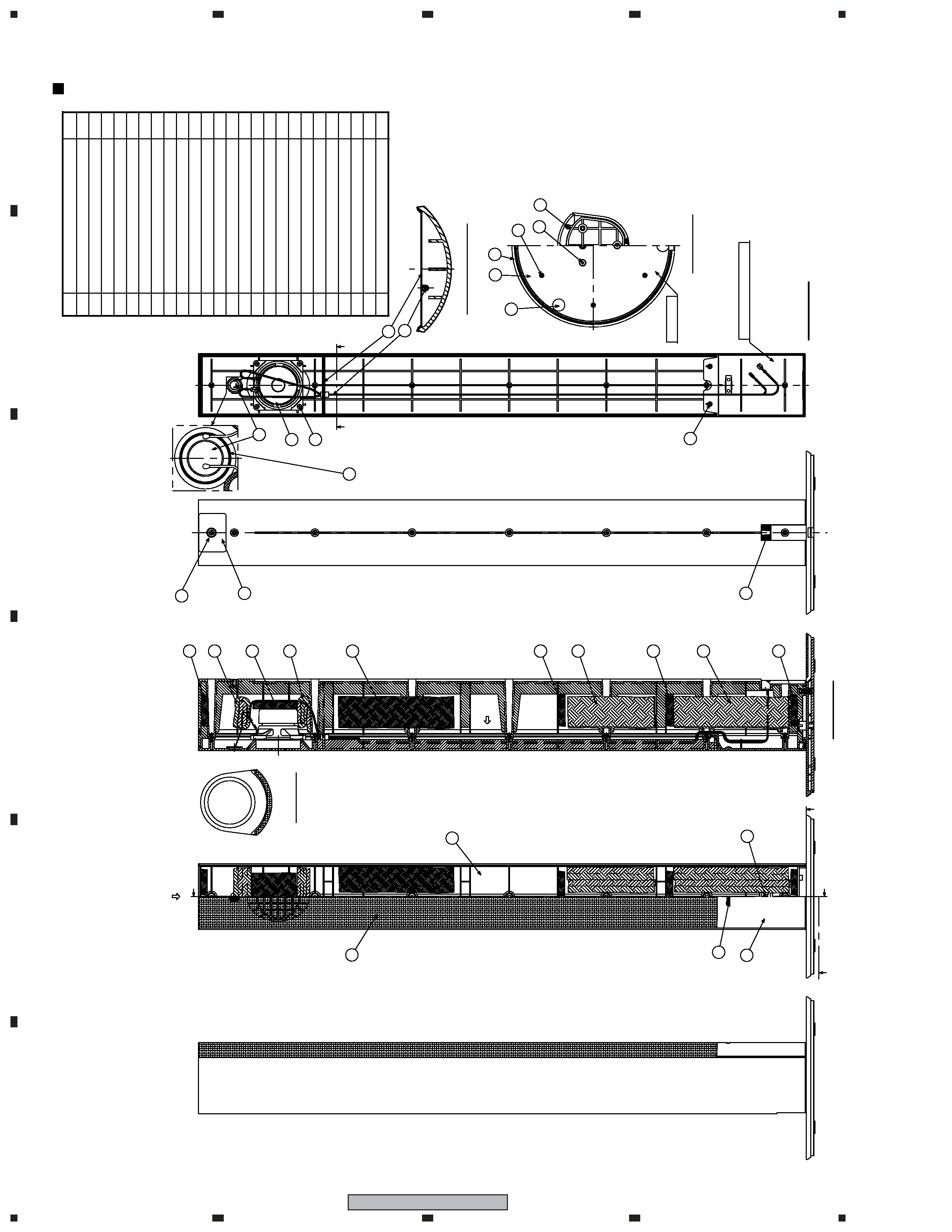
PRODUCT APPEARANCE
CS Assy (Front)
SECTION:C-C'(S=1/1)
FRONT
INSIDE
(VIEW
X1)
C
C'
Cosmetic
Plate
Assy
SECTION:B-B'
Base
Assy
TOP
VIEW
(VIEW
Y1)
SECTION:A-A'
X1
*No.24:
Apply
adhesives
to
all
around.
21
12
1
19
10
8
2
4
5
20
7
22
6
23
3
13
17
13
18
16
14
16
15
19
20
20
20
25
9
24
11
No.
Part
Name
Num.
1
2
3
4
5
6
7
8
9
10
11
12
13
14
15
16
17
18
19
20
21
22
23
24
25
Cabinet
Grille
Badge28
Base
Acoustic
Absorbent
(Polyester
Fiber)
Cosmetic
Plate
Base
Top
Non
Skid
Pad
Input
Terminal
Network
Assy
Speaker
(WF)
Packing
Speaker
(TW)
*Included
in
the
Network
Assy
1
1
1
1
1
1
3
1
1
1
1
1
2
2
2
2
1
2
4
9
7
6
3
-
1
Acoustic
Absorbent
(Duffel
Felt)
Screw
(3.5x8)
Screw
(3.5x12)
Screw
(3x8)
Screw
(M5x20)
Glue
Acoustic
Absorbent
(Polyester
Fiber)
Acoustic
Absorbent
(Polyester
Fiber)
Acoustic
Absorbent
(Duffel
Felt)
Acoustic
Absorbent
(Duffel
Felt)
*Accessary
Parts
Acoustic
Absorbent
(Duffel
Felt)
Model
Label
*This
screw(No.21)
is
fastened
first.
Next,
fasten
screws
in
order
toward
the
bottom.
A
A'
B
B'
Y1
5
1
23
4
1
2
3
4
C
D
F
A
B
E
S-DV232T
Num.
No.
Part
Name
Cabinet
1
2
2
8
1
1
Connecting
Cord
Input
Terminal
1
Speaker
1
1
1
Screw
(M3.5x8)
Acoustic
Absorbent
(Polyester
Fiber)
Acoustic
Absorbent
(Duffel
Felt)
Screw
(M3.5x12)
Grille
Badge
28
1
1
Model
Label
1
2
3
4
5
6
7
8
9
10
11
12
13
Packing
10
1
3
2
4
11
8
9
5
7
x8
x2
6
12
x2
CS Assy (Center)