ORDER NO.
PIONEER CORPORATION 4-1, Meguro 1-chome, Meguro-ku, Tokyo 153-8654, Japan
PIONEER ELECTRONICS (USA) INC. P.O. Box 1760, Long Beach, CA 90801-1760, U.S.A.
PIONEER EUROPE NV Haven 1087, Keetberglaan 1, 9120 Melsele, Belgium
PIONEER ELECTRONICS ASIACENTRE PTE. LTD. 253 Alexandra Road, #04-01, Singapore 159936
PIONEER CORPORATION 2007
S-A4SPT-VP
RRV3553
SPEAKER SYSTEM
S-A4SPT-VP
XTW/E5
1. FOR PRECAUTION OF REASSEBLY AND DISASSEMBLY
The grille is attached to the cabinet by catches.
Detach by pulling it toward you.
Replace a "skid" attached to yoke cap of woofer rear face
together when replacing a woofer.
The woofer is attached to the baffle board by 4 external
screws and face its terminal upward.
To detach it, first unfasten those screws. Then rotate the
woofer leftward, and as the terminal should turn leftward,
remove.
When attaching it, first set the woofer to the baffle board.
Then rotate the woofer rightward and face its terminal upward.
The tweeter is attached to the baffle board by 3 externalscrews.
To detach it, unfasten those screws.
When attaching it, face its terminal lower right.
The Network Assy is attached to the back board by 4 internal
screws.
To detach it, unfasten those screws.
When attaching it, face its cord (color : Red / Black) leftward.
T-ZZR MAR. 2007 Printed in Japan
S-A4SPT-VP
2
12
3
4
12
3
4
C
D
F
A
B
E
2. PARTS LIST
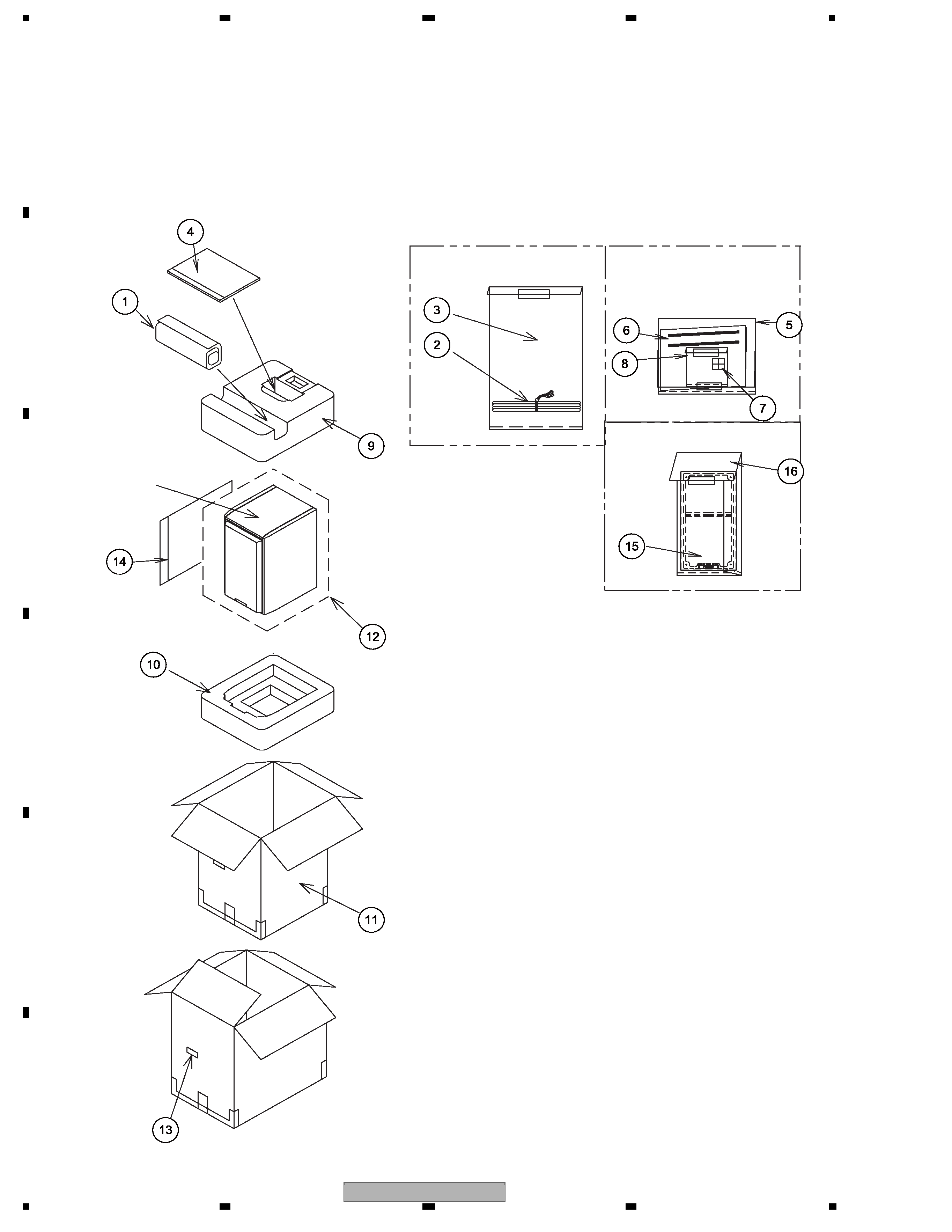
2.1 PACKING
NOTES : · Parts marked by " NSP " are generally unavailable because they are not in our Master Spare Parts List.
· The
> mark found on some component parts indicates the importance of the safety factor of the part.
Therefore, when replacing, be sure to use parts of identical designation.
No.
No.
12
Speaker System
1
4
9
10
11
13
(x2 /B, B' side)
15
16
No.14 : Accessories Set
7
5
6
8
No.4: Accessories Set
2
3
No.1: Accessories Set

S-A4SPT-VP
3
5
678
56
7
8
C
D
F
A
B
E
· PACKING Parts List
Mark No.
Description
Part No.
NSP 1
1..Accessories Set
SME3671
2
2..Speaker Wire
SDS1106
3
2..Polyethylene Bag S1
SHL1252
NSP 4
1..Accessories Set
SME3773
5
2..Polyethylene Bag S2
SHL1295
6
2..Operating Instructions
SRD1333
(English, French, German, Italian, Dutch,
Swedish, Spanish, Portuguese, Russian,
Danish, Norwegian, Finnish, Simp-Chinese,
Trad-Chinese)
NSP
2..Accessories Set
SME3758
7
3..Non Skid Pad
SEC2100
8
3..Polyethylene Bag S0
SHL1259
9
Protector (Top)
SHB6027
10
Protector (Bottom)
SHB6028
11
Packing Case
SHG2776
12
Polyethylene Bag S3
SHL1401
NSP 13
Label Serial
SRW1112
NSP 14
1..Accessories Set
SME3752
15
2..Grille
SMG1852
3..Logo
SAM1489
NSP
3..Grille Frame
SMH1039
3..Catch
SNK2584
16
2..Polyethylene Bag S2
SHL1295
S-A4SPT-VP
4
12
3
4
12
3
4
C
D
F
A
B
E
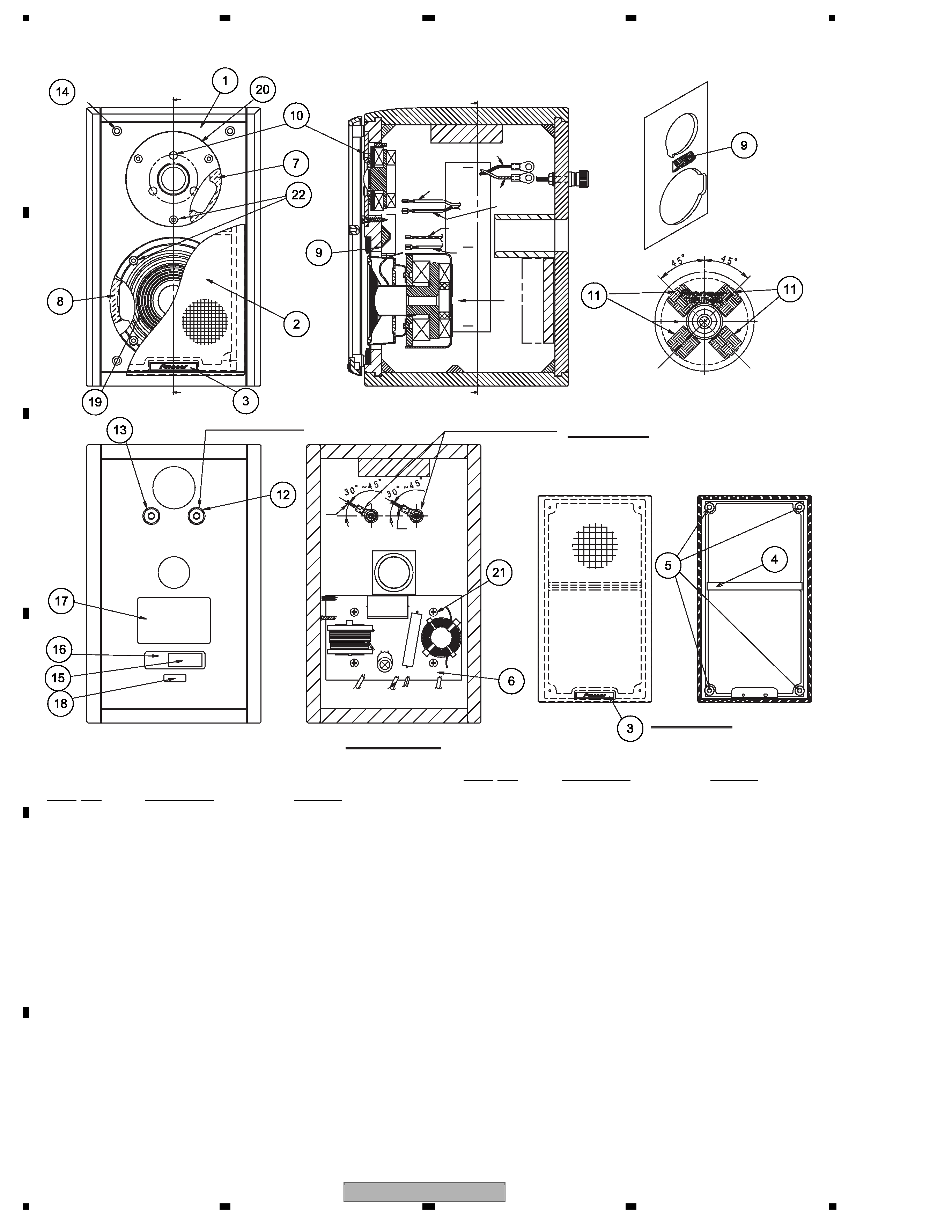
2.2 SPEAKER SYSTEM
· SPEAKER SYSTEM Parts List
5
4
3
19
2
8
17
14 (x4)
1
20
10 (x3)
9
22 (x7)
7
13
21
(x4)
6
12
9
3
11
11
B
A
Face its terminal upward.
(After setting the woofer to the baffle board,
rotate the woofer and its terminal is turned upward.)
Replace a "skid" together when replacing a woofer.
Black
Red
16
15
18
< Front View >
< Back View >
No.2 Grille
< BACK VIEW >
Arrow view A-A'
+ : Terminal (Red)
A'
Attach the terminals
at the angle to specify.
Black
Red
Transparence
Transparence
with White Line
White
White / Black
Netw
or
k
Assy
B: Arrow view
Mark No.
Description
Part No.
NSP 1
Cabinet
SMM2047
2
1..Grille
SMG1881
3
2..Logo
SAM1511
NSP 4
2..Grille Frame
SMH1039
5
2..Catch
SNK2584
6
1..Network Assy
SWN1782
NSP
2..Packing
SEC1963
2..Circuit Board
SNR1142
NSP 7
Gasket(Tw)
SEC1569
NSP 8
Gasket (Wf Side)
SEC1576
NSP 9
Damper (Baffle Block)
SEP1341
NSP 10
Damper (Tw)
SEP1352
11
Non Skid Pad (Damper)
SEC1964
12
Input Terminal (Red)
SKX6029
13
Input Terminal (Black)
SKX6030
14
Catch
SLH1091
NSP
Acoustic Absorbent
SMT1129
(Top,Bottom)
NSP
Acoustic Absorbent (Sides)
SMT1130
NSP
Acoustic Absorbent (Terminal) SMT1300
NSP
Acoustic Absorbent (Port)
SMT1301
NSP
Acoustic Absorbent (Tw Back) SMT1302
NSP
Acoustic Absorbent
SMT1341
NSP 15
Label Serial
SRW1111
NSP 16
Assistant Label
SRW1114
(for Label Serial)
NSP 17
Model Label
SAN3951
NSP 18
Country Label
SAN3876
19
Speaker (Woofer)
T10EU75-51D
20
Speaker (Tweeter)
FADD55-55D
21
Screw (for Network Assy)
BYC40P180FTB
22
Screw (for Wf, Tw)
SBA1259
Mark No.
Description
Part No.
S-A4SPT-VP
5
5
678
56
7
8
C
D
F
A
B
E
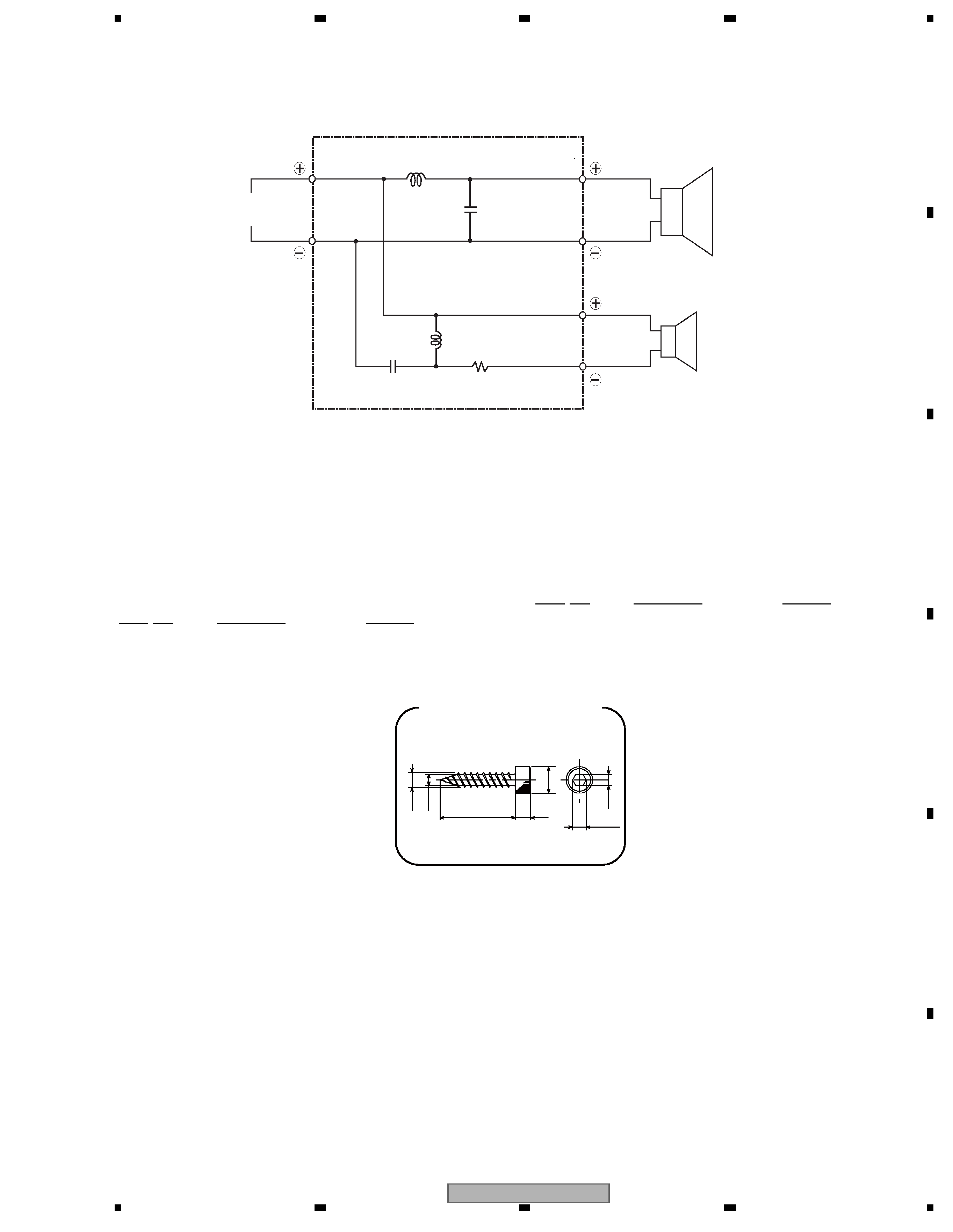
2.3 SCHEMATIC DIAGRAM
· NETWORK Parts List
Input
Terminal
Red
0.85 mH
0.36 mH
5.6
F/100 V
2.0 µF/250 V
C1
L2
C2
L1
Black
White
Transparence
Transparence
with White Line
White/Black
Woofer
Tweeter
R1
4.7
/10 W
Network Assy (SWN1782)
Mark No.
Description
Part No.
NSP 1
L1
0.85 mH
NSP 2
C1
5.6 uF/100 V
NSP 3
L2
0.36 mH
NSP 4
C2
2.0 uF/250 V
NSP 5
R1
4.7 / 10 W
Mark No.
Description
Part No.
Ø7
Ø3
Ø4
20
(3.6)
4
3
Screw (SBA1259)