ORDER NO.
PIONEER CORPORATION 4-1, Meguro 1-chome, Meguro-ku, Tokyo 153-8654, Japan
PIONEER ELECTRONICS (USA) INC. P.O. Box 1760, Long Beach, CA 90801-1760, U.S.A.
PIONEER EUROPE NV Haven 1087, Keetberglaan 1, 9120 Melsele, Belgium
PIONEER ELECTRONICS ASIACENTRE PTE. LTD. 253 Alexandra Road, #04-01, Singapore 159936
PIONEER CORPORATION 2006
T ZZS FEB. 2006 Printed in Japan
RRV3339
CONTENTS
1. PARTS LIST ................................................................................. 2
2. FOR PRECAUTION OF REASSEMBLY AND DISASSEMBLY ... 5
3. SCHEMATIC DIAGRAM ............................................................... 9
4. JIG .............................................................................................. 10
NOTE
For better audio quality, the receptacle terminals and terminal fittings of the speaker unit are
soldered. When disassembling/reassembling the speaker unit, be sure to follow the instructions
in this manual. If you will be working on the speaker unit with it turned on its side, lay it on a
piece of soft cloth, etc., to protect the cabinet from being scratched.
SPEAKER SYSTEM
S-7EX
XTW/E
This service manual is intended for qualified service technicians; it is not meant for the casual do-it-
yourselfer. Qualified technicians have the necessary test equipment and tools, and have been trained to
properly and safely repair complex products such as those covered by this manual.
Improperly performed repairs can adversely affect the safety and reliability of the product and may void the
warranty. If you are not qualified to perform the repair of this product properly and safely, you should not risk
trying to do so and refer the repair to a qualified service technician.
WARNING
This product contains lead in solder and certain electrical parts contain chemicals which are known to the state of California to
cause cancer, birth defects or other reproductive harm.
Health & Safety Code Section 25249.6 Proposition 65
2
1
23
4
12
3
4
C
D
F
A
B
E
S-7EX
8
6
17 (x4)
1-(1/2)
11
4
12
13
2-(1/2)
16 (x4)
15
32
10
2-(2/2)
3-(2/2)
Speaker system
9
7
1-(2/2)
3-(1/2)
14
5
18
(x2)
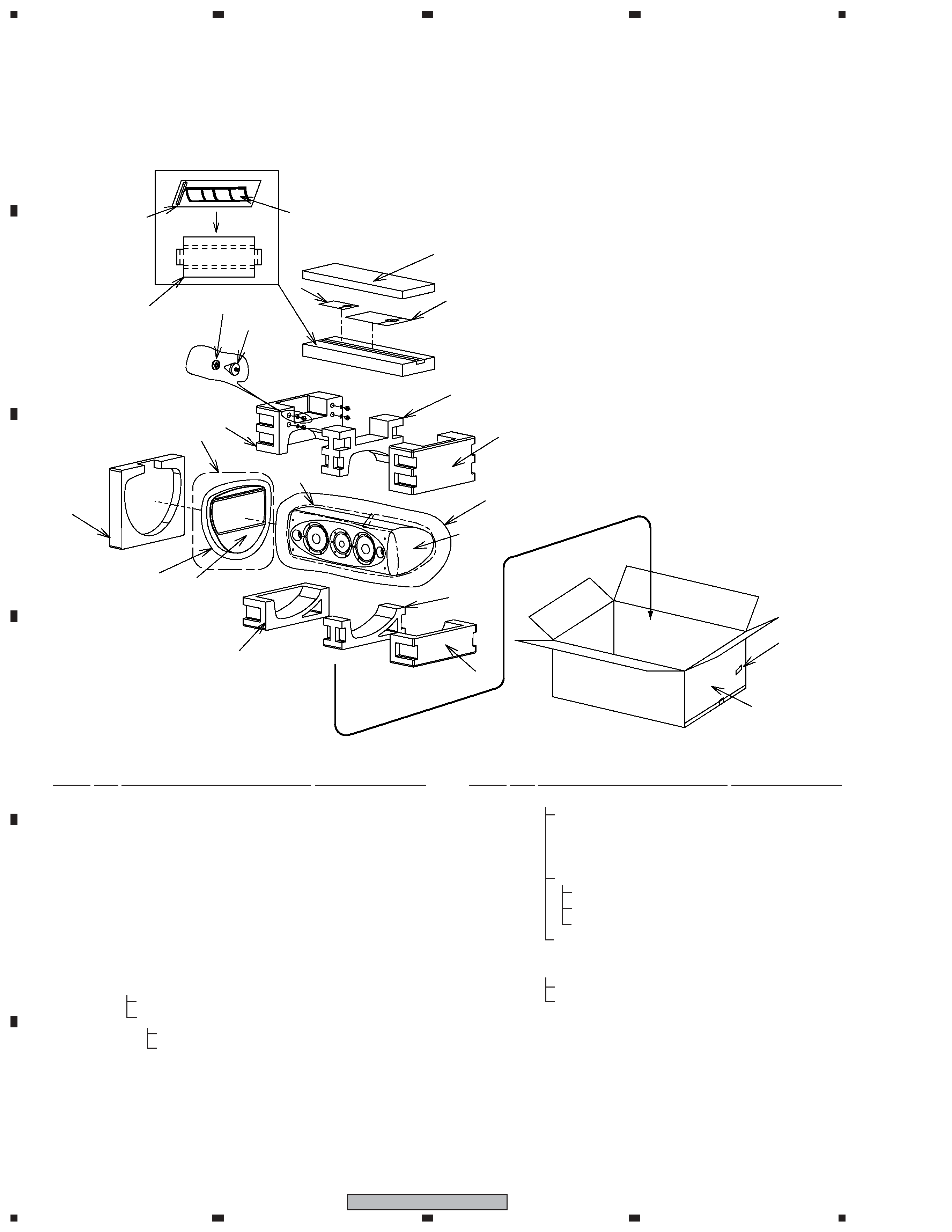
1. PARTS LIST
1.1 PACKING
1
Top Protector
SHA6084
2
Bottom Protector
SHA6085
3
Middle Protector
SHA6086
4
Protector
SHA6087
5
Protector Sheet
SHA6094
6
Protector (grille)
SHB6035
7
Protection Sheet
SHC1845
8
Protection Sheet
SHC6038
9
Protection Sheet
SHC6041
10 Packing Case
SHG6209
NSP
11 Accessory Set
SME6039
12
Protection Sheet
SHC6042
13
Speaker Base
SMS6018
NSP
Fung Nut M6
SBN1068
NSP
Non Skid Pad
SEC6071
NSP
14 Acceccory Set
SME3718
Operating lnstructions
SRD1312
(English, French, Spanish,
Simp-Chinese, Trad-Chinese)
NSP
Accessory Set
SME6041
Polyethylene Bag S0
SHL1259
Finishing Screws (for grille) SLH6013
Fastening Screws (for grille) SLH6016
Polyethylene Bag S2
SHL1265
NSP
15 Accessory Set (for grille holes)
SME6047
Caps (for grille holes)
SEC2068
Polyethylene Bag S0
SHL1259
16 Speaker Spikes
SBA6053
17 Spike Bases
SLA1057
NSP
18 Label Serial
SRW1112
PACKING Parts List
NOTES :
÷ Parts marked by " NSP " are generally unavailable because they are not in our Master Spare Parts List.
÷ The > mark found on some component parts indicates the importance of the safety factor of the part.
Therefore, when replacing, be sure to use parts of identical designation.
Mark
No.
Description
Part No.
Mark
No.
Description
Part No.
3
1
23
4
1
2
3
4
C
D
F
A
B
E
S-7EX
C
MID
lower
side
WF lower side
WF lower side
TW
Upper
side
Upper side for the HPF input terminals
Bottom side for the LPF input terminals
43
44
44
52 (x4)
39
51 (x4)
45 (x4)
31
50 (x6 /unit)
49
48
A
A'
Upper side
Lower side
B
B'
Connect the cords with
white tape to the
midrange unit.
Connect the cords with
black tape to the
midrange unit.
: Refer to the adhesive points on page 7
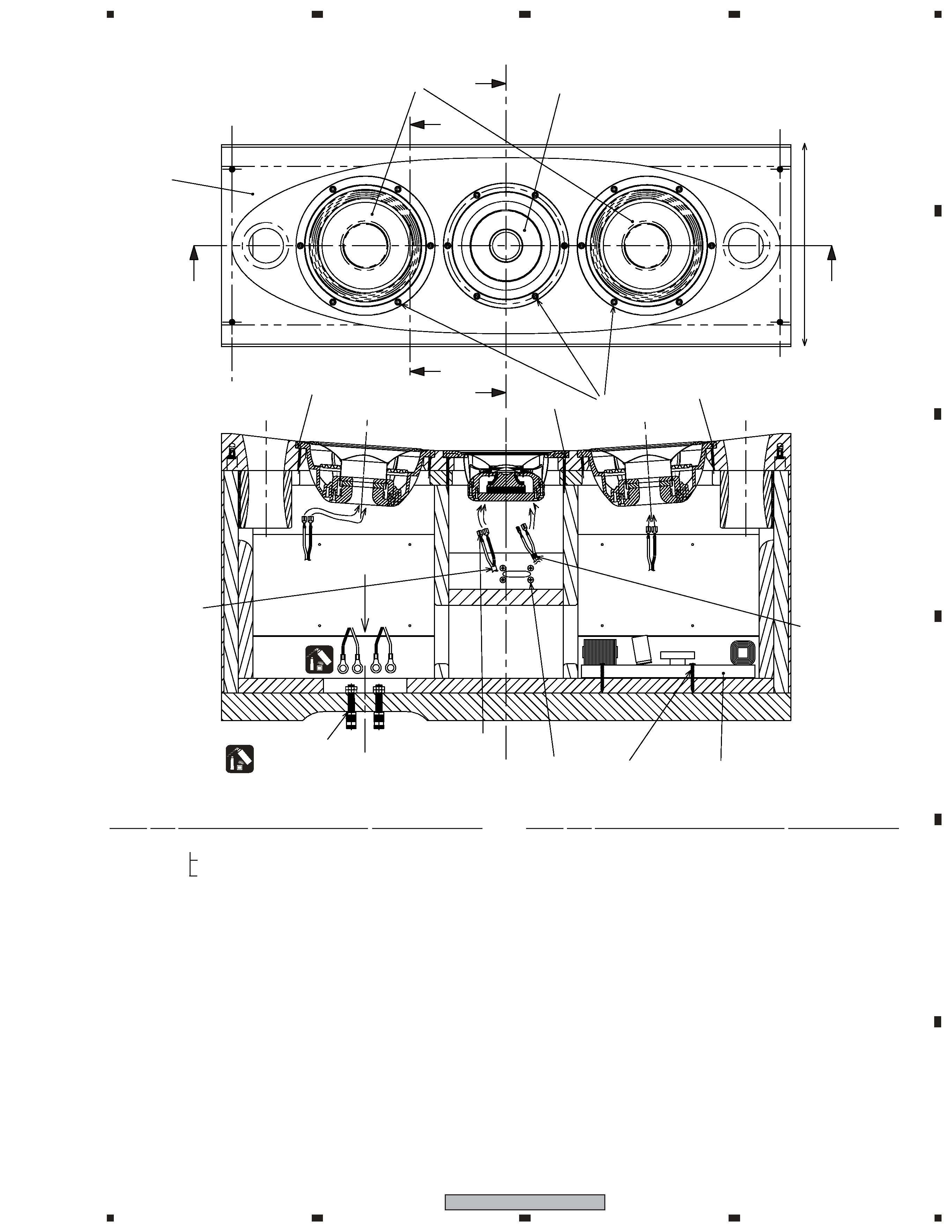
1.2 SPEAKER SYSTEM
NSP
31 Cabinet
SMM2027
NSP
Fung Nut M6 (for stand)
SBN1060
NSP
Fung Nut M4 (for grille)
SBN1066
39 Network Assy (low pass)
SWN1760
NSP
43 Gasket (for MID/TW)
SEC2031
NSP
44 Gasket (for WF)
SEC2032
NSP
45 Gasket (cabinet - input terminals) SEC2065
NSP
Acoustic Absorbent
SMT1313
(behind chamber, inside chamber)
NSP
Acoustic Absorbent
SMT1314
(WF - chamber)
NSP
Acoustic Absorbent
SMT1316
(WF upper and lower side board)
NSP
Acoustic Absorbent
SMT1320
(chamber/holes, input terminals)
NSP
Acoustic Absorbent
SMT1323
(behind duct, black)
SPEAKER SYSTEM Parts List
NSP
Acoustic Absorbent
SMT1324
(duct side, roll)
NSP
Acoustic Absorbent
SMT1326
(fold half both side, inside chamber)
NSP
Acoustic Absorbent
SMT1327
(around duct board)
NSP
Acoustic Absorbent
SMT1328
(duct board short side)
48 Speaker (WF)
B18IU60-52H
49 Speaker (MID/TW)
A14GR55-52DX
50 Hexagon Socket Screw
SBA1225
(for WF, MID/TW)
51 Screw (for NW assy)
SBA1260
52 Screw (for closure panel)
SBA1261
Mark
No.
Description
Part No.
Mark
No.
Description
Part No.
4
1
23
4
12
3
4
C
D
F
A
B
E
S-7EX
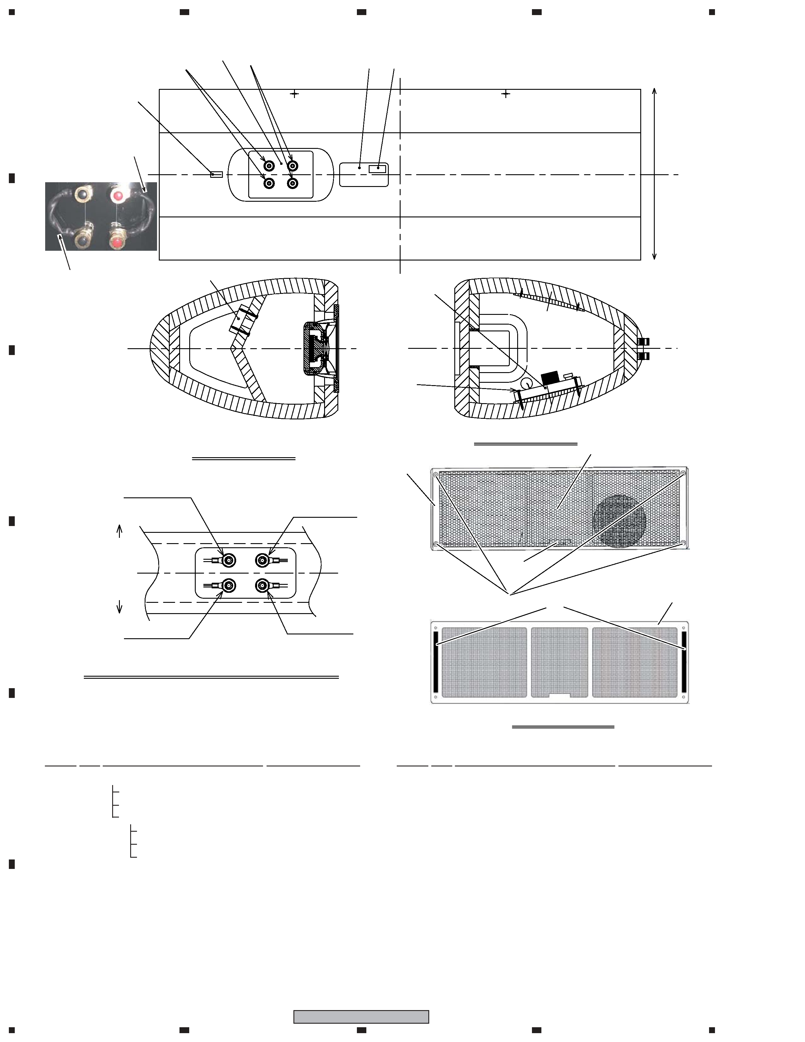
34
35
37
38
36
No.32 Grille
Front View
Back View
33
A-A' Sectional view
B-B' Sectional view
HPF input (+)
LPF input (+)
HPF input (-)
LPF input (-)
(40)
40
51
(x4)
Lower side
Upper side
Arrow view C: Detail of the input terminal board
42
42
Lower side
Upper side
46
47
54
41
53
55
The direction of the cord
holes must be vertical.
The direction of the cord
holes must be vertical.
32 Grille
SMG6095
33
Badge
FRAM-048
34
Packing
SEC6060
NSP
35
Grille Assy
SMG6096
NSP
36
Fung Nut
SBN6019
NSP
37
Grille Frame
SMC6003
NSP
38
Punching Net
SNH6014
40 Network Assy (high pass)
SWN1761
NSP
41 Sticker
SAN3871
42 Cord
SDS1192
SPEAKER SYSTEM Parts List
46 Input Terminal (Red)
SKX6027
47 Input Terminal (Black)
SKX6028
51 Screw (for NW assy)
SBA1260
NSP
53 Model Label
SAN3792
NSP
54 Country Label
SAN3782
NSP
55 Label Serial
SRW1111
Mark
No.
Description
Part No.
Mark
No.
Description
Part No.
5
1
23
4
1
2
3
4
C
D
F
A
B
E
S-7EX
How to disassemble
1 Loosen the finishing screws. Then remove the grille.
Note 1:
You may remove the fastening screws if they impede
disassembly.
How to reassemble
Finishing
Screws
Finishing Screws
Fastening
Screws
2 Place the grille with the badge located at the lower part,
aligning the 4 holes of the grille with the fastening screws
inserted in Step
1.
3 Tighten the supplied finishing screws into the fastening
screws to secure the grille.
Note 2:
Do not use a flathead screwdriver or a hexagonal wrench to
tighten the screws. Securing the screws too tightly may
damage the cabinet.
1 Insert the supplied fastening screws into the screw holes at
the four corners of the speaker front.
2. FOR PRECAUTION OF REASSEMBLY AND DISASSEMBLY
2.1 GRILLE
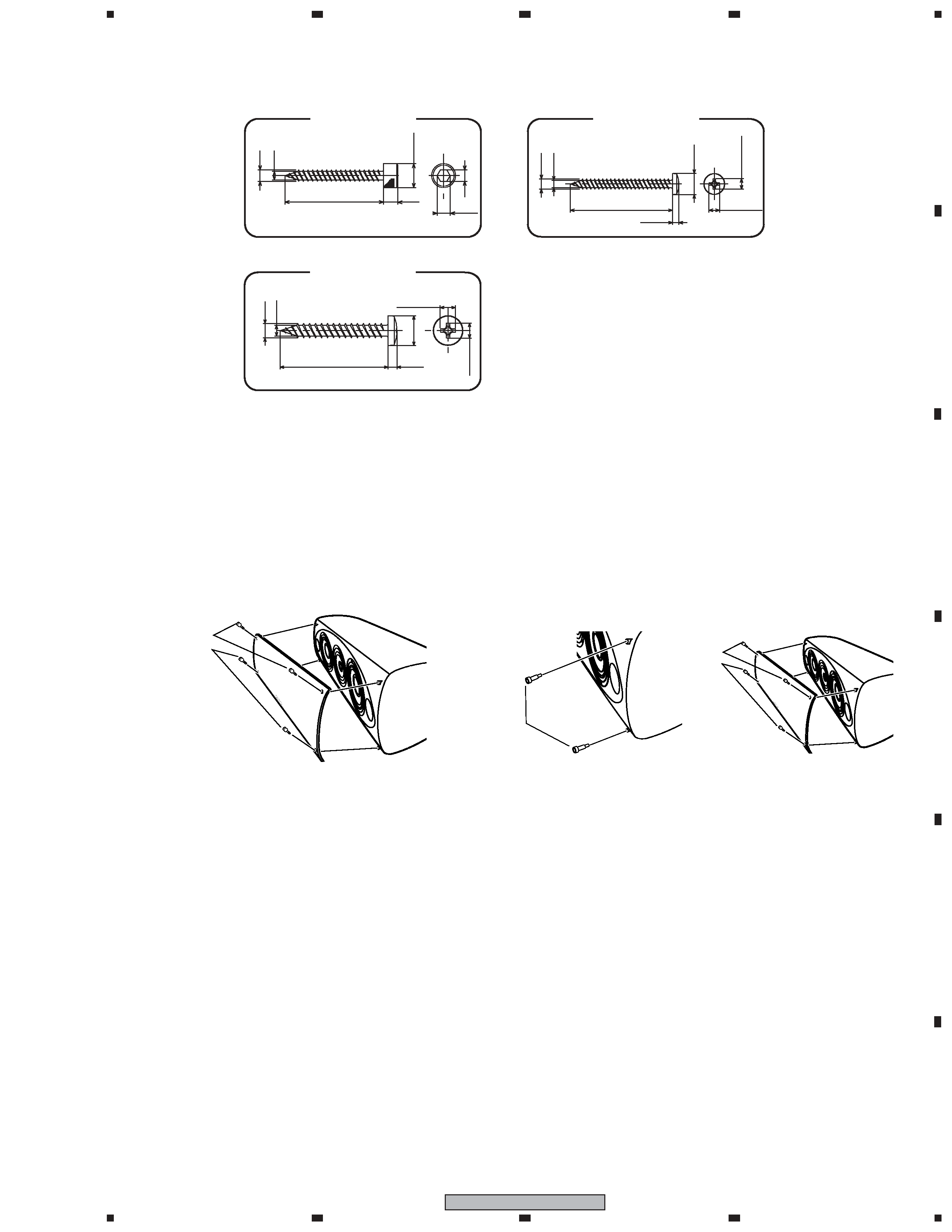
3
4
35
5
8.5
4
(4.6)
Screw (SBA1225)
3
4
8.3
2.5
30
4.2
max.
4.2 max.
Screw (SBA1260)
4.2 max.
8.3
3
4
40
2.5
4.2
max.
Screw (SBA1261)