ORDER NO.
PIONEER CORPORATION 4-1, Meguro 1-chome, Meguro-ku, Tokyo 153-8654, Japan
PIONEER ELECTRONICS (USA) INC. P.O. Box 1760, Long Beach, CA 90801-1760, U.S.A.
PIONEER EUROPE NV Haven 1087, Keetberglaan 1, 9120 Melsele, Belgium
PIONEER ELECTRONICS ASIACENTRE PTE. LTD. 253 Alexandra Road, #04-01, Singapore 159936
PIONEER CORPORATION 2008
S-4EX-W
RRV3848
T-ZZR OCT. 2008 Printerd in Japan
SPEAKER SYSTEM
S-4EX-W
/SXTW/E5
S-4EX-QL /SXTW/E5
This service manual is intended for qualified service technicians; it is not meant for the casual
do-it-yourselfer. Qualified technicians have the necessary test equipment and tools, and have been
trained to properly and safely repair complex products such as those covered by this manual.
Improperly performed repairs can adversely affect the safety and reliability of the product and may
void the warranty. If you are not qualified to perform the repair of this product properly and safely,
you should not risk trying to do so and refer the repair to a qualified service technician.
WARNING
This product contains certain electrical parts contain chemicals which are known to the State of California to cause cancer,
birth defects or other reproductive harm.
Health & Safety Code Section 25249.6 - Proposition 65
· For better audio quality, the receptacle terminals and terminal fittings of the speaker unit are soldered.
When disassembling/reassembling the speaker unit, be sure to follow the instructions in this manual. If
you will be working on the speaker unit with it turned on its side, lay it on a piece of soft cloth, etc., to
protect the cabinet from being scratched.
2
S-4EX-W
12
3
4
C
D
F
A
B
E
1
23
4
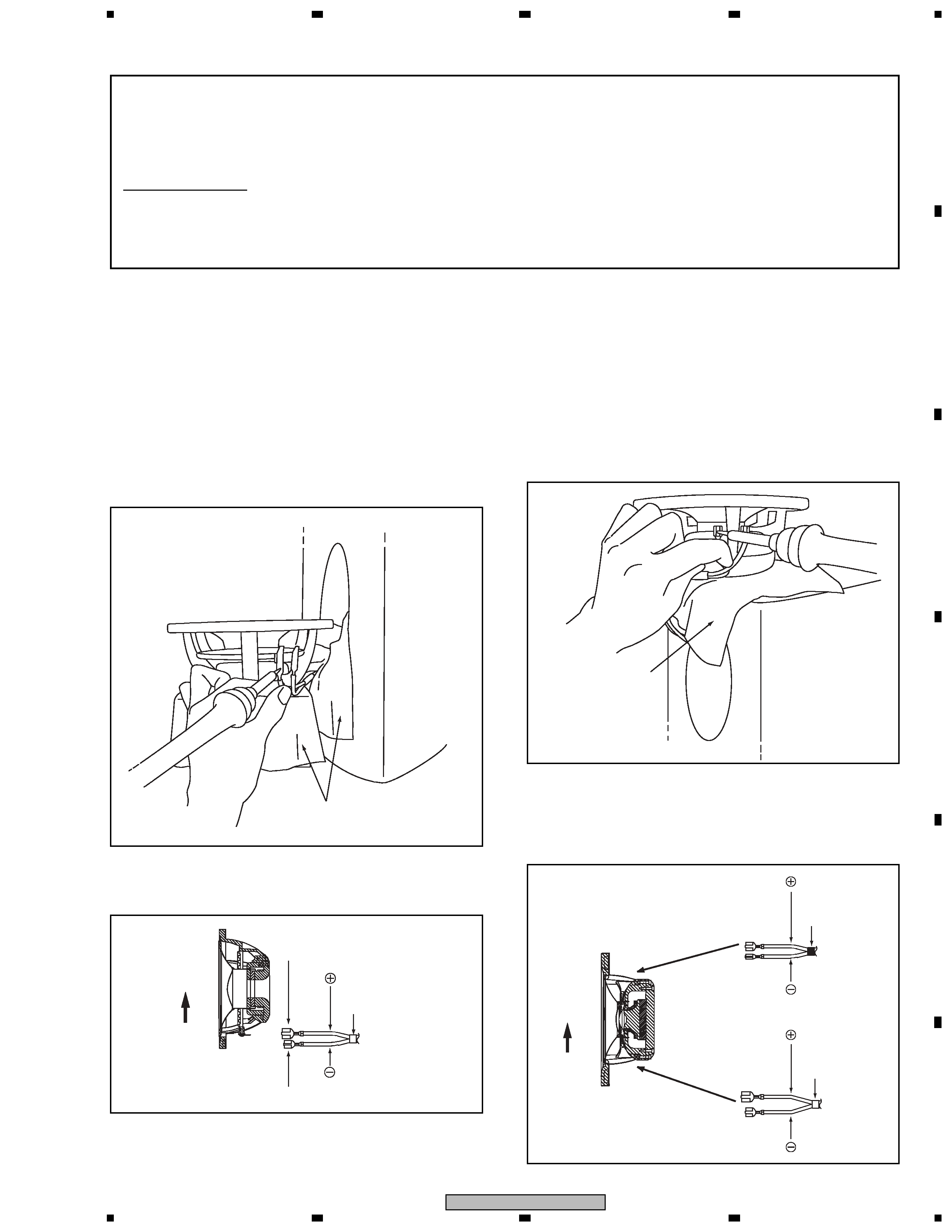
How to Attach/Detach the Grille Net
The grille net is provided with this speaker system. To attach
or detach the grille net, proceed as follows.
(1) To attach the grille net, align the six projections of the
grille net with the holes on the speaker unit then push it
in.
(2) To detach, hold the lateral edges of the upper part of the
grille net with both hands and gently pull it toward you to
detach the upper part of the grille net.
(3) Hold the lateral edges of the central part of the grille net
with both hands and gently pull it toward you to detach
the central part of the grille net.
(4) In the same way, hold the lateral edges of the lower part
of the grille net and pull it toward you. The entire grille
net will then be detached.
1. REASSEMBLY AND DISASSEMBLY PRECAUTIONS
1.1 GRILLE
3
S-4EX-W
5
67
8
5
6
7
8
C
D
F
A
B
E
[2] Detaching the CST unit
To work on the CST unit, place a piece of soft cloth for
protection on the upper plate to protect the cabinet from
being scratched, then place the CST unit on it.
· The midrange unit and tweeter are integrated into a coaxial
unit. This CST-unit speaker is attached to the baffle board
with four hexagon-socket-set screws from the outside.
When disassembling, remove all these screws, pull out the
CST-unit speaker, then remove the solder to disconnect
the cords.
· When reattaching, after connecting the cords, solder the
terminals for the woofer then place the woofer so that the
terminal board comes to the bottom-plate side.
· When reattaching, connect the cord with black tape to the
tweeter and the cord with white tape to the midrange unit
then solder the terminals. Place the CST unit so that the
terminal board of the midrange unit comes to the bottom-
plate side then turn it counterclockwise slightly to secure it.
[1] Detaching the woofer
To work on the woofer, provide a stand with a height of
approx. 15 cm, place a piece of soft cloth for protection on it,
then place the woofer on the cloth.
Drape a piece of soft cloth from around the edge of the hole
where the woofer was attached to the duct, to protect the
cabinet from being scratched.
· The woofer is attached to the baffle board with 6 hexagon-
socket-set screws from the outside.
When disassembling, remove all these screws, pull out the
woofer, then remove the solder to disconnect the cords.
1.2 SPEAKER UNIT
For better audio quality, the receptacle terminals and terminal fittings of the speaker
unit are soldered. When disassembling/reassembling the speaker unit, be sure to
refer to the following figures.
Tools to be used
· Hexagonal wrench (4 mm): GGK1024
· Soldering iron: GGK1069
· Lead-free solder: GYP1006
Piece of soft cloth for protection
Piece of soft cloth
for protection
White tape
Terminal size: Extra large
Terminal size: Large
: White with Black-line
: White
Woofer
Upper
side
White tape
Black tape
Terminal size:
Large
Terminal size:
Large
Terminal size:
Small
Terminal size:
Extra large
: White with
Black-line
: White with
Black-line
: White
: White
Upper
side
CST unit
Terminal board
of the tweeter
Terminal board
of the midrange
4
S-4EX-W
12
3
4
C
D
F
A
B
E
1
23
4
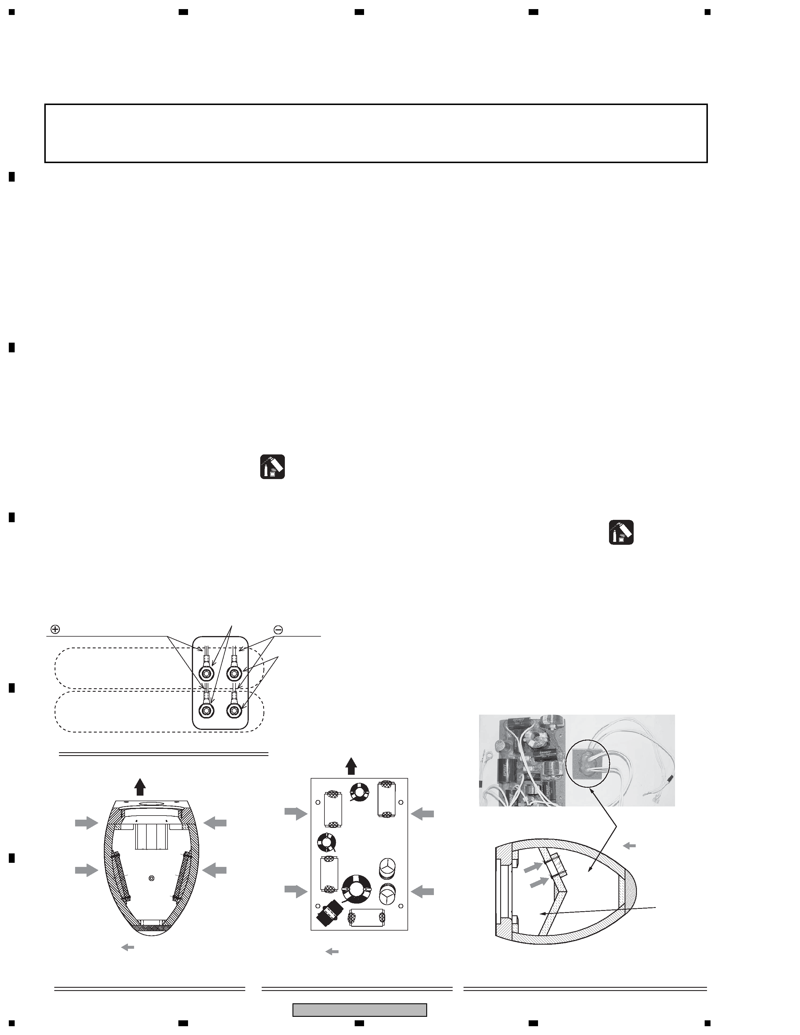
1.3 NETWORK ASSY
Before removing the Network Assy, remove the grille and each speaker unit then
disconnect the cords from the speaker unit.
· For removal/reattachment of the Network Assy for the woofer: Only the woofer must be removed beforehand.
· For removal/reattachment of the Network Assy for the midrange unit and the tweeter: Removal of all the units is
required.
[1] Network Assy for the Woofer
· The Network Assy for the woofer is located inside the left
panel behind the woofer and secured with four screws.
(1) Remove the acoustic absorbent pads that are located near
the input terminals.
(2) Remove the two nuts that secure the round connectors from
the lower input terminals.
(See Fig. 2-1. Tool: Box wrench, 14 mm/GGH-002)
(3) Remove the four screws that secure the Network Assy then
pull the Assy out through the hole where the woofer was
attached. (See Fig. 2-2.)
(4) When reattaching, pass the Network Assy through the hole
where the woofer was attached then secure it in place with
the four screws. (See Fig. 2-2.)
(5) Among the two pairs of cords from the Network Assy,
connect the cords with the round connectors to the lower
input terminals and secure them with the nuts.
(See Fig. 2-1. Tool: Box wrench, 14 mm/GGH-002)
(6) Apply adhesive to the secured nuts.
(Adhesive: DIABOND black/GYL-014)
(7) Reinstall the acoustic absorbent pads near the input
terminals.
(8) Connect and solder the remaining pair of cords from the
Network Assy to the woofer and reinstall the woofer in the
cabinet.
[2] Network Assy for the midrange unit
and the tweeter
· The Network Assy for the midrange unit and the tweeter
is located inside the right panel behind the woofer and
attached with four screws.
(1) Remove the acoustic absorbent pads that are located near
the input terminals, inside and at the rear of the chamber,
and behind the chamber.
(2) Remove the two nuts that secure the round connectors from
the upper input terminals.
(See Fig. 2-1. Tool: Box wrench, 14 mm/GGH-002)
(3) Remove the four screws that secure the closure panel
inside the chamber, remove the four screws that secure the
Network Assy, and pull the Network Assy out through the
hole where the woofer was attached.
(See Figs. 2-3 and 2-4. Tool: Screwdriver/GGK1012)
(4) When reattaching, pass the Network Assy through the hole
where the woofer was attached and secure it in place, using
the four screws.(See Fig. 2-3. Tool: Screwdriver/GGK1012)
(5) Among the cords from the Network Assy, connect the cords
with the round connectors to the upper input terminals and
secure them with the nuts.
(See Fig. 2-1. Tool: Box wrench, 14 mm/GGH-002)
(6) Apply adhesive to the secured nuts.
(Adhesive: DIABOND black/GYL-014)
(7) Pass the closure panel and the two pairs of cords from it
through behind the chamber then secure the closure panel
from inside the chamber, using the four screws.
(See Fig. 2-4.)
(8) Reinstall the acoustic absorbent pads near the input
terminals, inside and at the rear of the chamber, and behind
the chamber.
(9) Connect and solder the cords to the CST-unit speaker and
reinstall it in the cabinet.
: Screws
: Screws
Upper side
Bottom side
Front side
Chamber
: Screws
Fig. 2-1: Input terminals (inside the cabinet)
Fig. 2-2: Specifications for attaching
the Network Assy for the woofer
Fig. 2-3: Specifications for attaching the
Network Assy for the midrange/tweeter
Fig. 2-4: Specifications
for attaching the closure panel
(cross-sectional view of the CST unit speaker)
: White with Black line
From the Network Assy
for the midrange/tweeter
: White
Apply adhesive.
From the Network Assy
for the woofer
Note: The NW Assy shown in this photo is for the
S-1EX, but the shape of the closure panel is the
same.
Apply adhesive.
Be sure to apply
adhesive only to the
head of a screw,
but not around the nut.
Closure panel
5
S-4EX-W
5
67
8
5
6
7
8
C
D
F
A
B
E
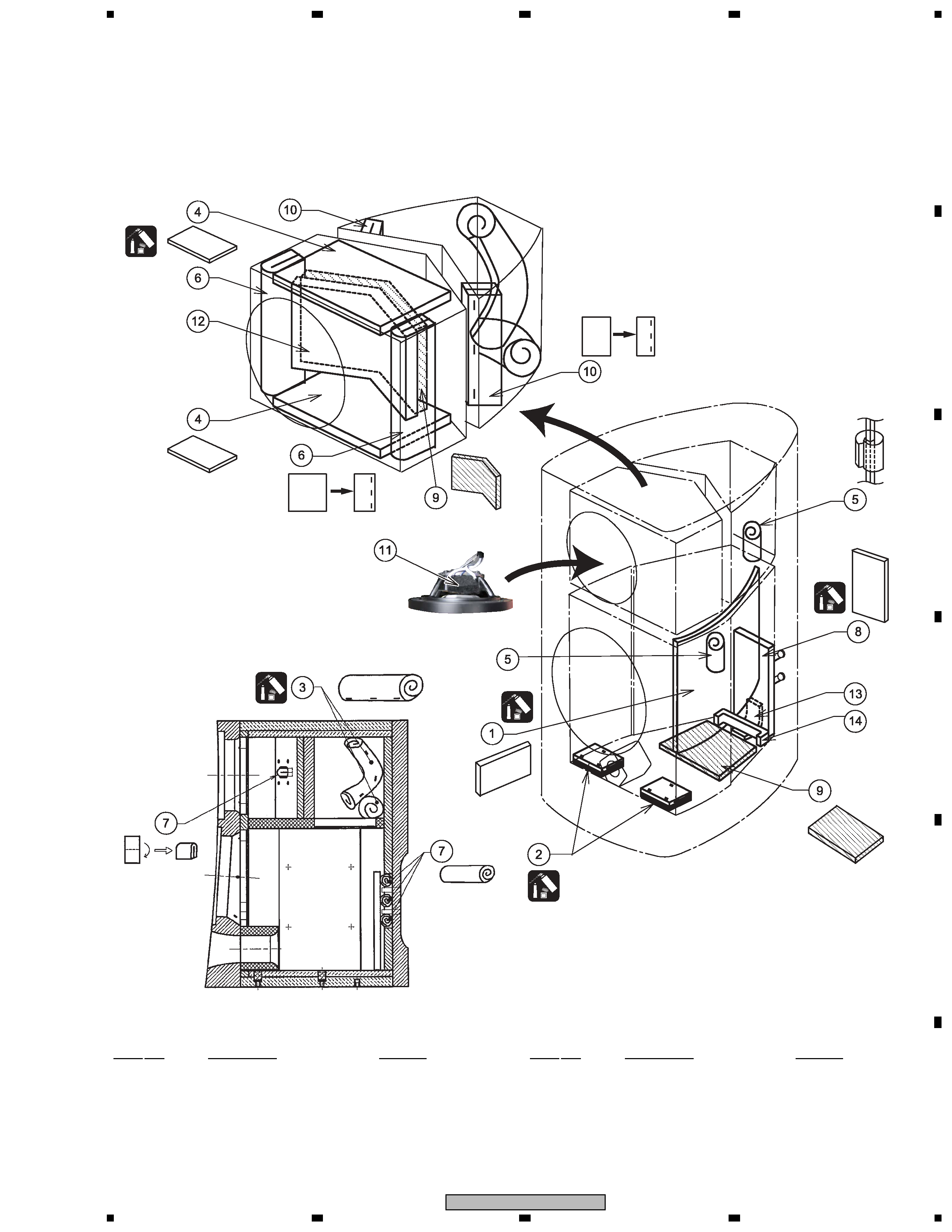
[3] Removal/Reattachment of Acoustic absorbent pads
Removal/reattachment of acoustic absorbent pads is necessary before or after removal/reattachment of the Network Assy.
Note:
When reattaching the Network Assy for the midrange unit and the tweeter, before reattaching the closure panel, be sure to
remove the acoustic absorbent pads located behind the chamber. If the closure panel pinches an acoustic absorbent pad when
it is secured, air leakage may occur, which may result in poor performance of this speaker system.
(1/2)
(1/2)
(1/2)
(2/2)
(2/2)
(1/2)
(2/2)
(2/2)
Place an acoustic absorbent pad
between the tweeter terminal board of
the CST unit and the cords.
NSP 1
Acoustic Absorbent
FRMV-126
NSP 2
Acoustic Absorbent
SMT1391
NSP 3
Acoustic Absorbent
FRMV-128
NSP 4
Acoustic Absorbent
FRMV-130
NSP 5
Acoustic Absorbent
SMT1392
NSP 6
Acoustic Absorbent
FRMV-135
NSP 7
Acoustic Absorbent
FRMV-136
NSP 8
Acoustic Absorbent
SMT1323
NSP 9
Acoustic Absorbent
SMV6021
NSP 10
Acoustic Absorbent
SMV2270
NSP 11
Acoustic Absorbent
SMV2271
NSP 12
Acoustic Absorbent
FRMV-129
NSP 13
Acoustic Absorbent
SMV2272
NSP 14
Acoustic Absorbent
SMT1395
Acoustic Absorbent Parts List
Mark No.
Description
Part No.
Mark No.
Description
Part No.