ORDER NO.
PIONEER CORPORATION 4-1, Meguro 1-chome, Meguro-ku, Tokyo 153-8654, Japan
PIONEER ELECTRONICS (USA) INC. P.O. Box 1760, Long Beach, CA 90801-1760, U.S.A.
PIONEER EUROPE NV Haven 1087, Keetberglaan 1, 9120 Melsele, Belgium
PIONEER ELECTRONICS ASIACENTRE PTE. LTD. 253 Alexandra Road, #04-01, Singapore 159936
PIONEER CORPORATION 2007
S-3EX-QL
PRT-145
SPEAKER SYSTEM
S-3EX-QL
XDCN5
S-3EX-W XDCN5
* This product weighs about 48 kg. For a repair, be sure that two people work on it. If the unit must
be placed 90° from normal for work, place it on cushioning, such as soft cloth, for protection.
* For a better audio quality, the receptacles and the terminal fittings of the speaker unit are
soldered.
For a repair, two people are required: one for holding the removed unit and the other for soldering.
SERVICE PRECAUTIONS
T-ZZR AUG. 2007 Printed in Japan
Even though the suffix is different between /XDCN5 and /SXTW/EW5,
both models are completely same product.
S-3EX-QL
2
12
3
4
12
3
4
C
D
F
A
B
E
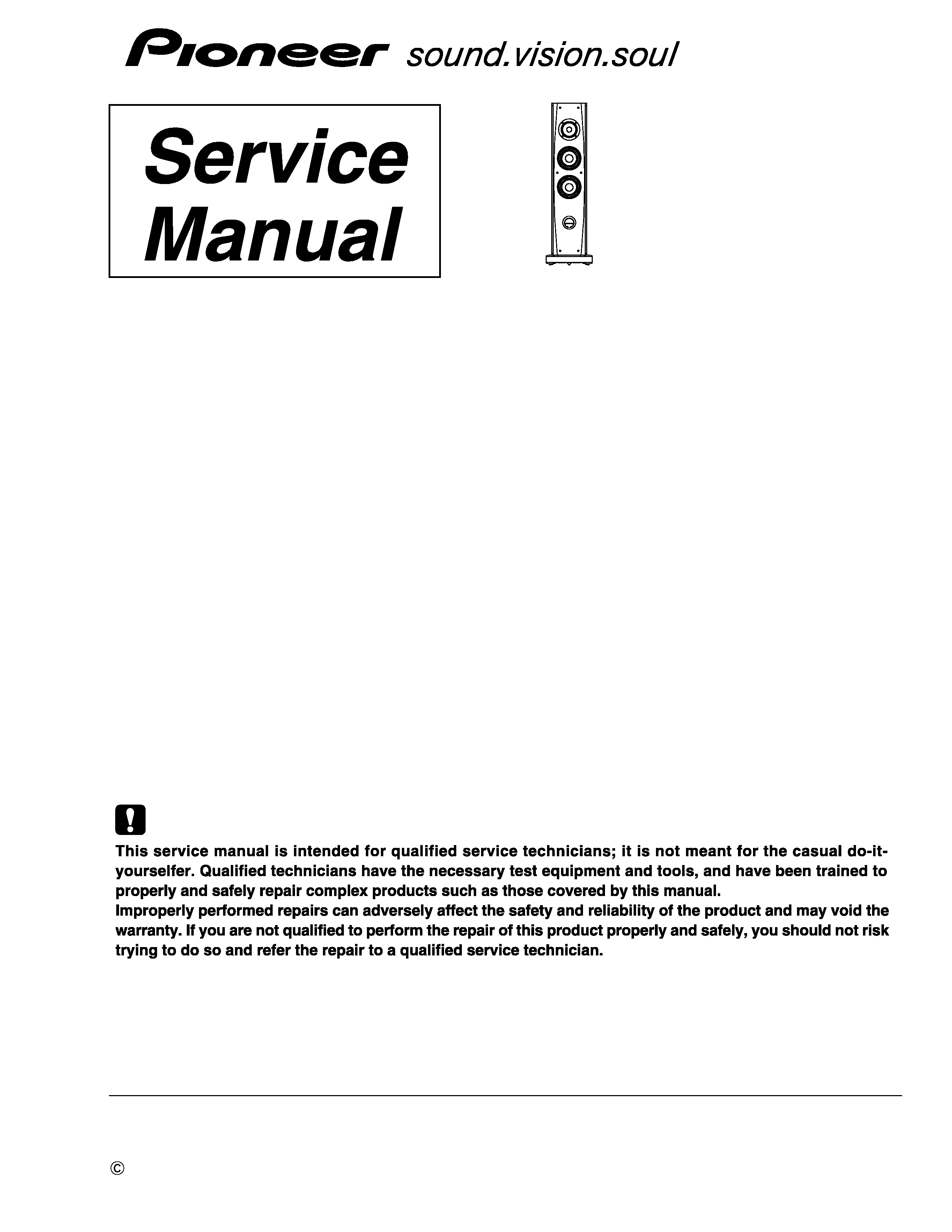
1. NOTES ON DISASSEMBLING AND REASSEMBLING
1.1 GRILL
1.2 SPEAKER UNIT
How to detach and reattach
To detach/reattach the grill, proceed as follows:
1 To reattach the grill, align the six projections on the grill
with the holes on the main unit. Then push the grill into
the unit.
2 To detach the grill, first hold the lower part of the grill
with both hands and lightly pull it out toward you to
detach the lower part.
3 Hold the middle part of the grill with both hands and
lightly pull it out toward you to detach the middle part.
4 In the same manner, pull out the upper part of the grill
so that the whole grill is detached from the unit.
For a better audio quality, the receptacles and the terminal fittings of the speaker unit are soldered.
For a repair, two people are required: one for holding the removed unit and the other for soldering.
Tools to be used:
· Hexagonal wrench/4 mm: GGK1024
· Soldering iron: GGK1069
· Lead-free solder: GYP1006
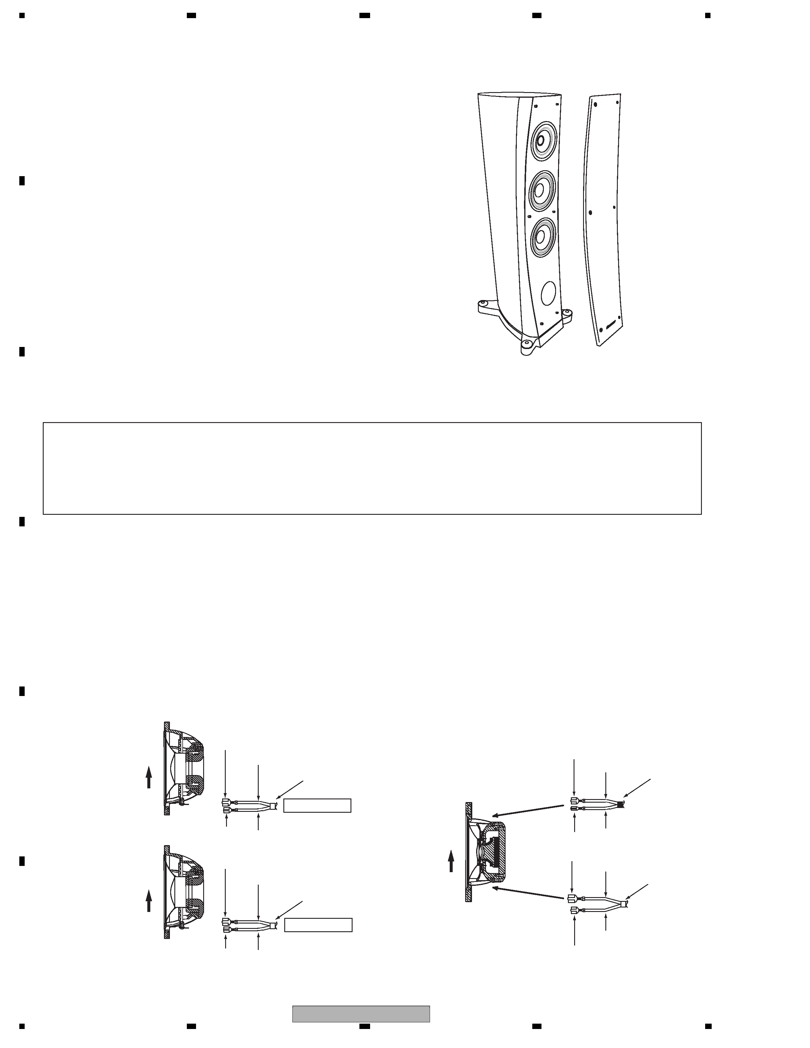
The woofer is attached to the baffle plate from the outside
with the six hexagon socket set screws.
To remove the woofer, remove those screws first, remove
the woofer, then remove the solder to disconnect the
cables.
When reattaching the woofer
(1) After making connections, solder the terminals of the
woofers.
(2) Attach the woofer so that the terminal block comes to
the lower part.
The CST unit is an integrated coaxial unit of the midrange
unit and the tweeter. The CST unit is attached to the
baffle plate from the outside with the four hexagon socket
set screws.
To remove the CST unit, remove those screws first,
remove the CST unit, then remove the solder to discon
nect the cables.
When reattaching the CST unit
(1) Connect the cable coated with black tape to the tweeter
and the cable coated with white tape to the midrange
unit then solder the terminals.
(2) Attach the CST unit so that the terminal block of the
midrange unit comes to the lower part.
White tape
Terminal size: Extra large
Terminal size: Large
Terminal size: Extra large
Terminal size: Large
Note: Even if the speaker unit shown in the illustrations in this manual may differ from your prodoct, the procedures described here are common.
White tape
White tape
: White + black line
: White
: White
: White + black line
Longer cable
Shorter cable
Upper woofer
Lower woofer
Up
Up
Tweeter terminal
plate
Midrange terminal
plate
Black tape
: White + black line
: White
: White + black line
: White
CST unit
Up
Terminal size: Large
Terminal size: small
Terminal size: Extra large
Terminal size: Large
S-3EX-QL
3
56
7
8
56
7
8
C
D
F
A
B
E
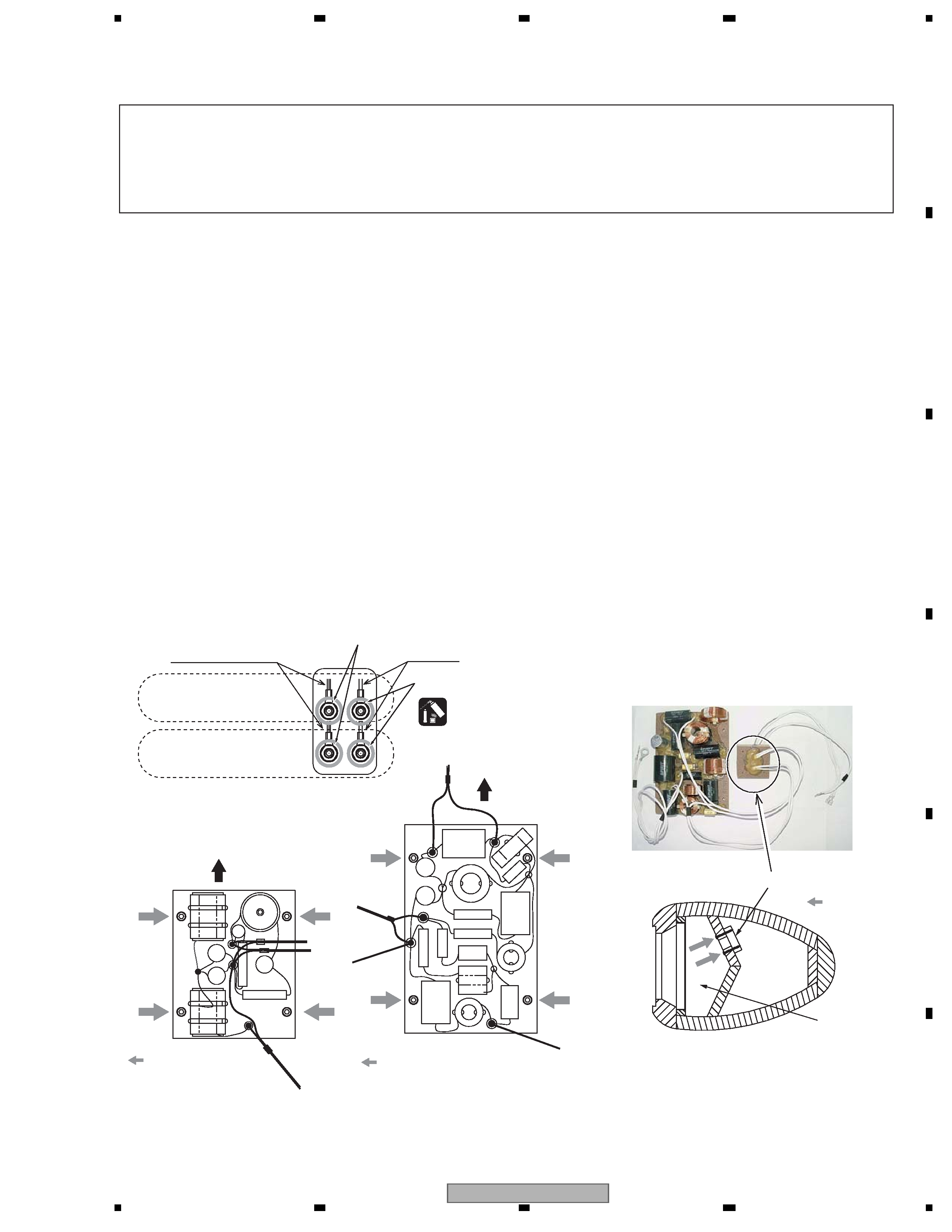
1.3 NETWORK ASSY
1.3.1 NETWORK ASSY FOR THE WOOFER
Fig. 2-3: Attachment specifications
of the Network Assy for the CST unit
Fig. 2-1: Input terminals (within the cabinet)
+: White/black line
-: White
From the Network Assy
for the woofer
From the Network Assy
for the CST unit
Apply adhesive.
Apply adhesive.
: Direction for
tightening a
screw
Fig. 2-4: Attachment specifications for the enclosure
plate (cross-sectional view of the speaker at the
location of the CST unit)
*The photo is of the Network Assy for the S-1EX,
but the structure for attachment is the same.
Enclosure plate
Chamber
Fig. 2-2: Attachment specifications
of the Network Assy for the woofer
Top
: Direction for
tightening a screw
FR
WN-184
Top
: Direction for
tightening a screw
FR
WN-185
· Network Assy for the woofer: After removing only the woofer, remove the Network Assy.
· Network Assy for the CST unit: After removing all speaker units, remove the Network Assy.
Tools to be used:
· Hexagonal wrench/4 mm: GGK1024
· Box wrench/14 mm: GGH-002
· DIABOND (black) (DB-1600WB): GYL-014
Before removing the Network Assy, first remove the grill and the speaker unit(s) then disconnect the cables connected to the
speaker unit.
The Network Assy is attached to the interior side of the right side
panel near the upper woofer with four screws.
(1) Remove the acoustic absorbent placed at the rear of the input
terminals. (See Figs. 2-5 and 2-6.)
(2) Remove the two nuts of the lower input terminals and
disconnect the round terminals. (See Fig. 2-1.)
(3) Remove the four screws that secure the Network Assy and pull
out the Network Assy through the hole for the woofer.
(See Fig. 2-2.)
(4) For reattachment of the Network Assy, pass it through the hole
for the woofer and secure it with the original four screws.
(See Fig. 2-2.)
(5) Connect the terminals of the cable coated with black tape
among the three pairs of cables coming from the Network Assy
to the lower input terminals and secure them with the nuts.
(6) Apply adhesive to the secured nuts. (Adhesive: DIABOND
black/GYL-014)
(7) Insert the acoustic absorbent at the rear of the input terminals.
(See Figs. 2-5 and 2-6.)
(8) Connect the terminals of the two pairs of cables coated with
white tape among the three pairs of cables coming from the
Network Assy to the input terminals of the woofer and solder
them. Then attach the woofer to the cabinet.
1.3.2 NETWORK ASSY FOR THE CST UNIT
The Network Assy is attached to the interior side of the left side
panel near the lower woofer with four screws.
(1) Remove the acoustic absorbent placed at the rear of the input
terminals, at the back within the chamber, and at the back of the
chamber. (See Figs. 2-5 to 2-8.)
(2) Remove the two nuts of the upper input terminals and discon
nect the round terminals. (See Fig. 2-1.)
(3) Remove the four screws that secure the enclosure plate from
within the chamber. Remove the four screws that secure the
Network Assy and pull out the Network Assy through the hole
for the woofer. (See Figs. 2-3 and 2-4.)
(4) For reattachment of the Network Assy, pass it through the hole
for the woofer and secure it with the original four screws.
(See Fig. 2-3.)
(5) Connect the round terminals of the cable among the cables
coming from the Network Assy to the upper input terminals and
secure them with the nuts.
(6) Apply adhesive to the secured nuts.
(Adhesive: DIABOND black/GYL-014)
(7) Pass the enclosure plate with two pairs of cables connected to
it from the rear of the chamber and secure the enclosure plate
to the plate from inside the chamber with the four original
screws. (See Fig. 2-4.)
(8) Place acoustic absorbent at the rear of the input terminals, at
the rear within the chamber, and at the rear of the chamber.
(See Figs. 2-5 to 2-8.)
(9) After making connection to the CST unit and soldering, attach
the cabinet.
S-3EX-QL
4
12
3
4
12
3
4
C
D
F
A
B
E
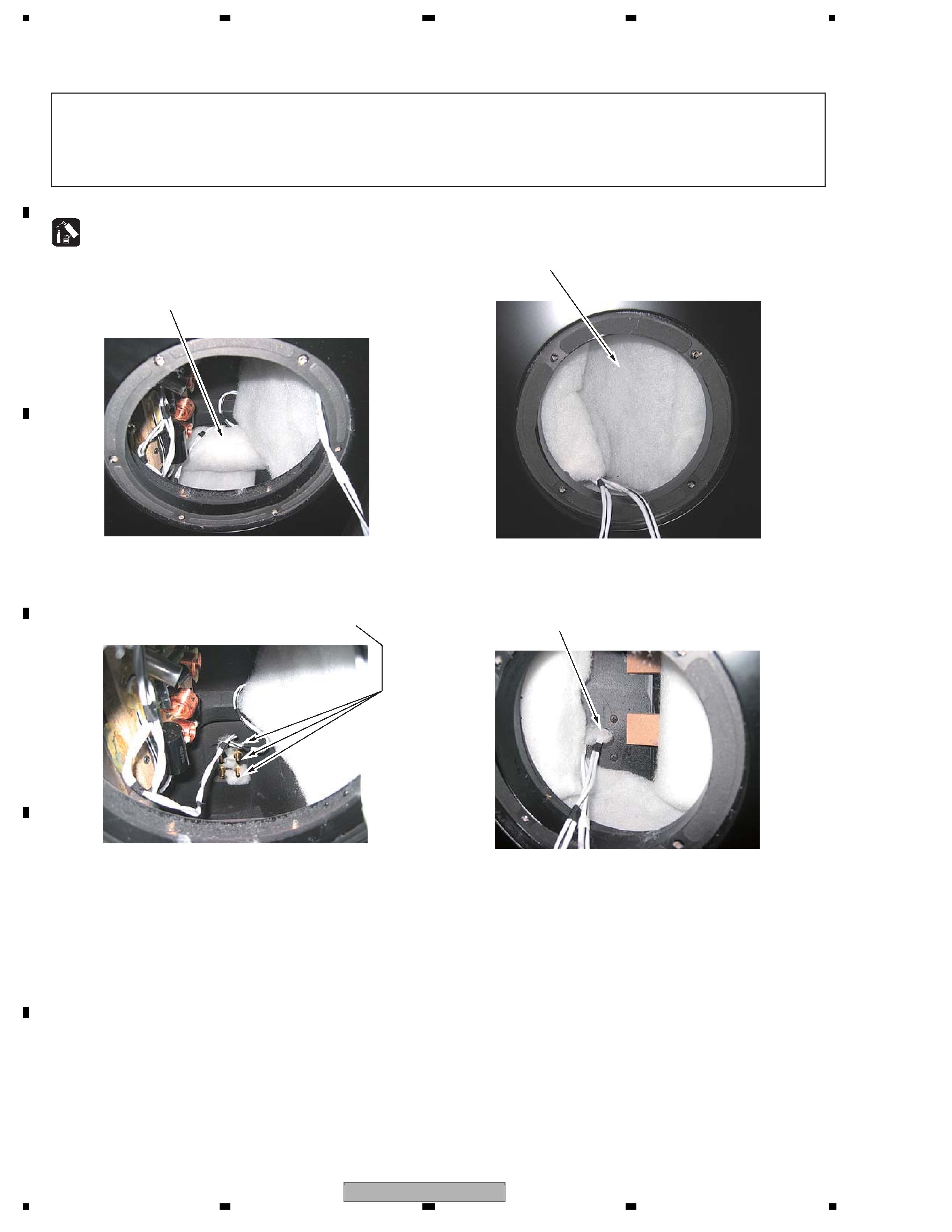
Fig. 2-5: View after the lower woofer is removed (1)
Fig. 2-7: View after the CST unit is removed (1)
Fig. 2-8: View after the CST unit is removed (2)
Fig. 2-6: View after the lower woofer is removed (2)
1 Remove this acoustic absorbent. When replacing, roll the
acoustic absorbent, then push it in under the reinforcing
crosspiece. Only this acoustic absorbent needs fixing with
adhesive. Therefore, before pushing it in, be sure to apply
adhesive to the side panel of the cabinet.
1 Remove this piece of acoustic absorbent. When replacing, place
it along the interior side of the chamber so that it forms a U
shape.
2 Remove these pieces of acoustic absorbent.
When replacing, fold them in two and push them in.
2 Remove this piece of acoustic absorbent (near the enclosure
plate). When replacing, fold it in two and push it in.
3 Do not remove the acoustic absorbent near the Network Assy
for the CST unit. Remove only the rolled pieces of acoustic
absorbent placed at the rear of the chamber for the CST unit.
In this state, detach/reattach the Network Assy for the CST unit
and the enclosure plate.
(Adhesive: DIABOND black/GYL-014)
1. Acoustic absorbent near the input-terminal plate
2. Acoustic absorbent within the chamber for the CST
unit
3. Acoustic absorbent near the Network Assy for the
CST unit
1.3.3 ACOUSTIC ABSORBENTS
Note:
Upon reattachment of the Network Assy for the CST unit, before reattaching the enclosure plate, be sure to remove the
acoustic absorbent placed at the rear of the chamber. If part of the acoustic absorbent is pinched between the enclosure plate
and the plate when the enclosure plate is secured, air leakage may occur and the best performance of the speaker may not be
obtained.
When the Network Assy is detached then reattached, removal and placement of the acoustic absorbent is required.
S-3EX-QL
5
56
7
8
56
7
8
C
D
F
A
B
E
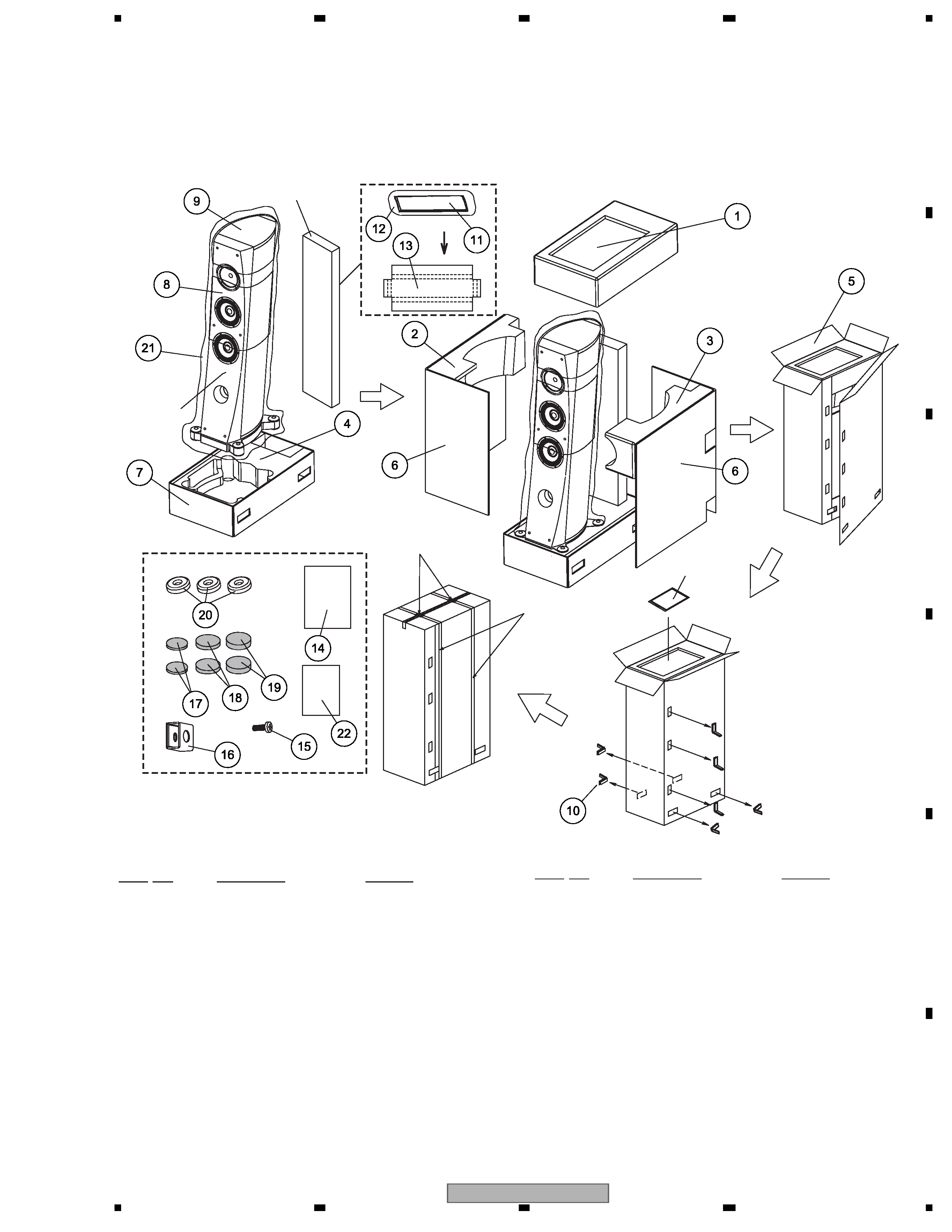
2. EXPLODED VIEWS AND PARTS LIST
2.1 PACKING
PACKING Parts List
NOTES :
· The
> mark found on some component parts indicates the importance of the safety factor of the part.
Therefore, when replacing, be sure to use parts of identical designation.
· Parts marked by " NSP " are generally unavailable because they are not in our Master Spare Parts List.
Speaker
System
Pet Band
(Pet Band)
Stopper
Accessory Set
Accessory Set
Grille Set
X7
Mark No.
Description
Part No.
1
Top Protector
SHA6157
2
Middle Protector(L)
SHA6129
3
Middle Protector(R)
SHA6130
4
Bottom Protector
SHA6156
5
Packing Case (S-3EX-QL)
SHG6290
5
Packing Case (S-3EX-W)
SHG6267
6
Protector (Middle)
SHB6054
7
Packing Case (Bottom)
SHB6055
8
Protection Sheet
SHC6067
(for Side of Cabinet)
9
Protection Sheet
SHC6068
(for Top of Cabinet)
10
Joint for Packing Case
SNK6124
11
Grille Assy
FRMG-230
12
Protecton Sheet (for Grille)
SHC6065
13
Protector (Grille)
SHB6056
14
Owner's Manual
FRRD-214
15
Screw (for Fastener)
BMZ40P120FTB
16
Fastener
FRNH-028
17
Spacer (Thickness 3 mm)
FREC-110
18
Spacer (Thickness 4 mm)
FREC-111
19
Spacer (Thickness 5 mm)
FREC-112
20
Leg Spike Gasket
SBG6002
21
Protection Sheet
SHC6064
NSP 22
Warranty Card
SRY6055
Mark No.
Description
Part No.