1. SAFETY INFORMATION ...................................... 2
2. EXPLODED VIEWS AND PARTS LIST ................ 4
3. SCHEMATIC DIAGRAM ..................................... 16
4. PCB CONNECTION DIAGRAM .......................... 56
5. PCB PARTS LIST ............................................... 63
6. ADJUSTMENT .................................................... 71
CONTENTS
7. GENERAL INFORMATION ................................ 87
7.1 DIAGNOSIS ................................................. 87
7.1.1 DIAGNOSIS .......................................... 87
7.1.2 DISASSEMBLY .................................... 98
7.1.3 STYLING ............................................ 104
7.2 BLOCK DIAGRAM ...................................... 106
8. PANEL FACILITIES AND SPECIFICATIONS .. 112
RVD-XG10
HIGH RESOLUTION LCD PROJECTOR
ORDER NO.
ARP2979
O - IZG JUNE 1998 Printed in Japan
PIONEER ELECTRONIC CORPORATION 4-1, Meguro 1-Chome, Meguro-ku, Tokyo 153-8654, Japan
PIONEER ELECTRONICS SERVICE, INC. P.O. Box 1760, Long Beach, CA 90801-1760, U.S.A.
PIONEER ELECTRONIC (EUROPE) N.V. Haven 1087, Keetberglaan 1, 9120 Melsele, Belgium
PIONEER ELECTRONICS ASIACENTRE PTE. LTD. 501 Orchard Road, #10-00 wheelock Place, Singapore 238880
PIONEER ELECTRONIC CORPORATION 1998
RVA-VK10
VIDEO CIRCUIT KIT
c
Type
Model
Power Requirement
Remarks
RVD-XG10 RVD-XG10ED RVA-VK10
TUCYL
AC110-240V
ZY
THIS MANUAL IS APPLICABLE TO THE FOLLOWING MODEL(S) AND TYPE(S).
RVD-XG10ED
RVA-VK10 is a dealer option model for RVD-XG10ED.
2
RVD-XG10, RVD-XG10ED, RVA-VK10
1.1 SAFETY PRECAUTIONS
(FOR USA MODEL ONLY)
NOTICE : Comply with all cautions and safety related notes located
on or inside the cabinet and on the chassis or mirror case.
The following precautions should be observed:
1. When service is required, even though the FRONT PROJECTOR
an isolation transformer should be inserted between power line
and the set in safety before any service is performed.
2. When replacing a chassis in the set, all the protective devices
must be put back in place, such as barriers, nonmetallic knobs,
adjustment and compartment covershields, isolation resistor-
capacitor, etc.
3. When service is required, observe the original lead dress.
Extra precaution should be taken to assure correct lead dress in
the high voltage circuitry area.
4. Always use the manufacturer's replacement components.
Especially critical components as indicated on the circuit diagram
should not be replaced by other manufacture's.
Furthermore where a short circuit has occurred, replace those
components that indicate evidence of overheating.
5. Before returning a serviced set to the customer, the service
technician must thoroughly test the unit to be certain that it is
completely safe to operate without danger of electrical shock,
and be sure that no protective device built into the set by the
manufacturer has become defective, or inadvertently defeated
during servicing.
Therefore, the following checks should be performed for the
continued protection of the customer and service technician.
Leakage Current Cold Check
With the AC plug removed from the l20V AC 60Hz source, place a
jumper across the two plug prongs. Turn the AC power switch on.
Using an insulation tester (DC 500V), connect one lead to the
jumpered AC plug and touch the other lead to each exposed metal
part (screwheads on the rear), particularly any exposed metal part
having a return path to the chassis. Exposed metal parts having a
return path to the chassis should have a minimum resistor reading
of 0.3M
and a maximum resistor reading of 5M. Any resistor
value below or above this range indicates an abnormality which
requires corrective action. Exposed metal parts not having a return
path to the chassis will indicate an open circuit.
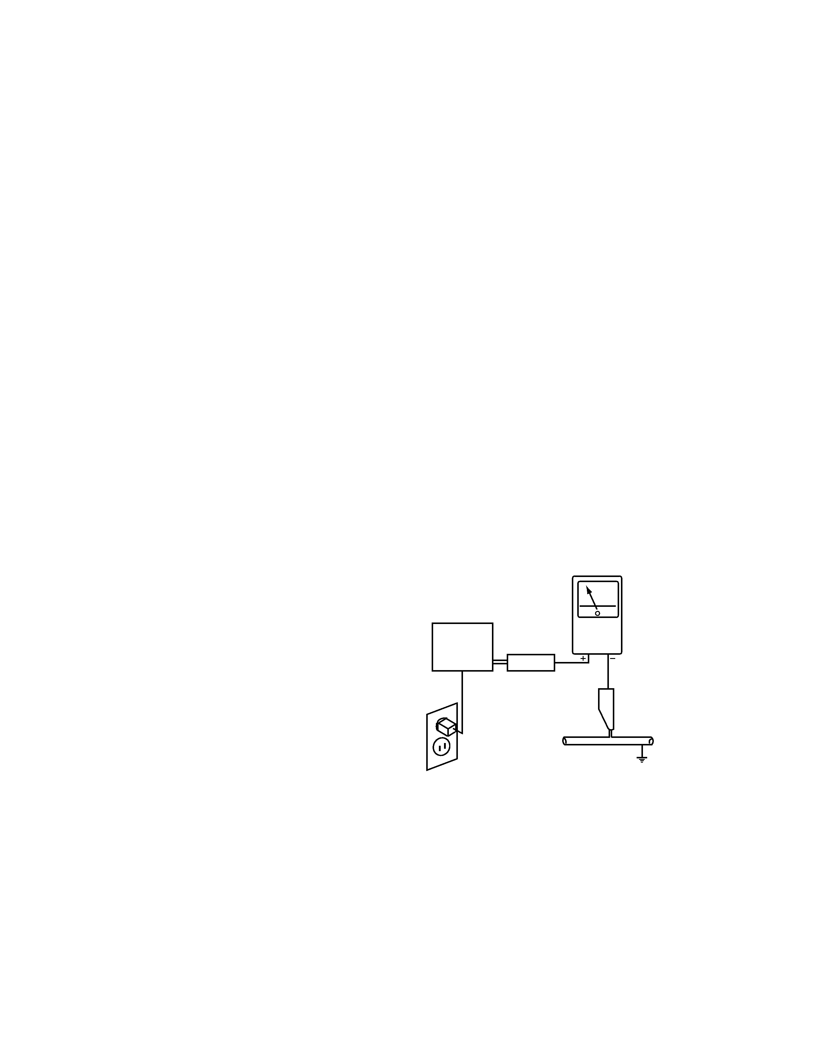
Leakage Current Hot Check
Plug the AC line cord directly into a 120V AC 60Hz outlet (do not
use an isolation transformer for this check). Turn the AC power
switch on.
Using a "Leakage Current Tester (Simpson Model 229 equivalent)",
measure for current from all exposed metal parts of the cabinet
(screwheads on the rear), particularly any exposed metal part having
a return path to the chassis, to a known earth ground (water pipe,
conduit, etc.). Any current measured must not exceed 0.5mA.
ANY MEASUREMENTS NOT WITHIN THE LIMITS
OUTLINED ABOVE ARE INDICATIVE OF A
POTENTIAL SHOCK HAZARD AND MUST BE
CORRECTED BEFORE RETURNING THE SET TO
THE CUSTOMER.
1. SAFETY INFORMATION
This service manual is intended for qualified service technicians ; it is not meant for the casual do-it-
yourselfer. Qualified technicians have the necessary test equipment and tools, and have been trained
to properly and safely repair complex products such as those covered by this manual.
Improperly performed repairs can adversely affect the safety and reliability of the product and may
void the warranty. If you are not qualified to perform the repair of this product properly and safely, you
should not risk trying to do so and refer the repair to a qualified service technician.
WARNING
This product contains lead in solder and certain electrical parts contain chemicals which are known to the state of California to cause
cancer, birth defects or other reproductive harm.
Health & safety code section 25249.6 - proposition 65
Leakage
current
tester
Reading should
not be above
0.5mA
Device
under
test
Test all
exposed metal
surfaces
Also test with
plug reversed
(Using AC adapter
plug as required)
Earth
ground
AC Leakage Test
3
RVD-XG10, RVD-XG10ED, RVA-VK10
1.2 PRODUCT SAFETY NOTICE
Many electrical and mechanical parts in PIONEER set have special
safety related characteristics. These are often not evident from
visual inspection nor the protection afforded by them necessarily
can be obtained by using replacement components rated for higher
voltage, wattage, etc. Replacement parts which have these special
safety characteristics are identified in this Service Manual.
Electrical components having such features are identified by marking
with a
on the schematics and on the parts list in this Service
Manual.
The use of a substitute replacement component which dose not have
the same safety characteristics as the PIONEER recommended
replacement one, shown in the parts list in this Service Manual,
may create shock, fire, or other hazards.
Product Safety is continuously under review and new instructions
are issued from time to time. For the latest information, always
consult the current PIONEER Service Manual. A subscription to,
or additional copies of, PIONEER Service Manual may be obtained
at a nominal charge from PIONEER.
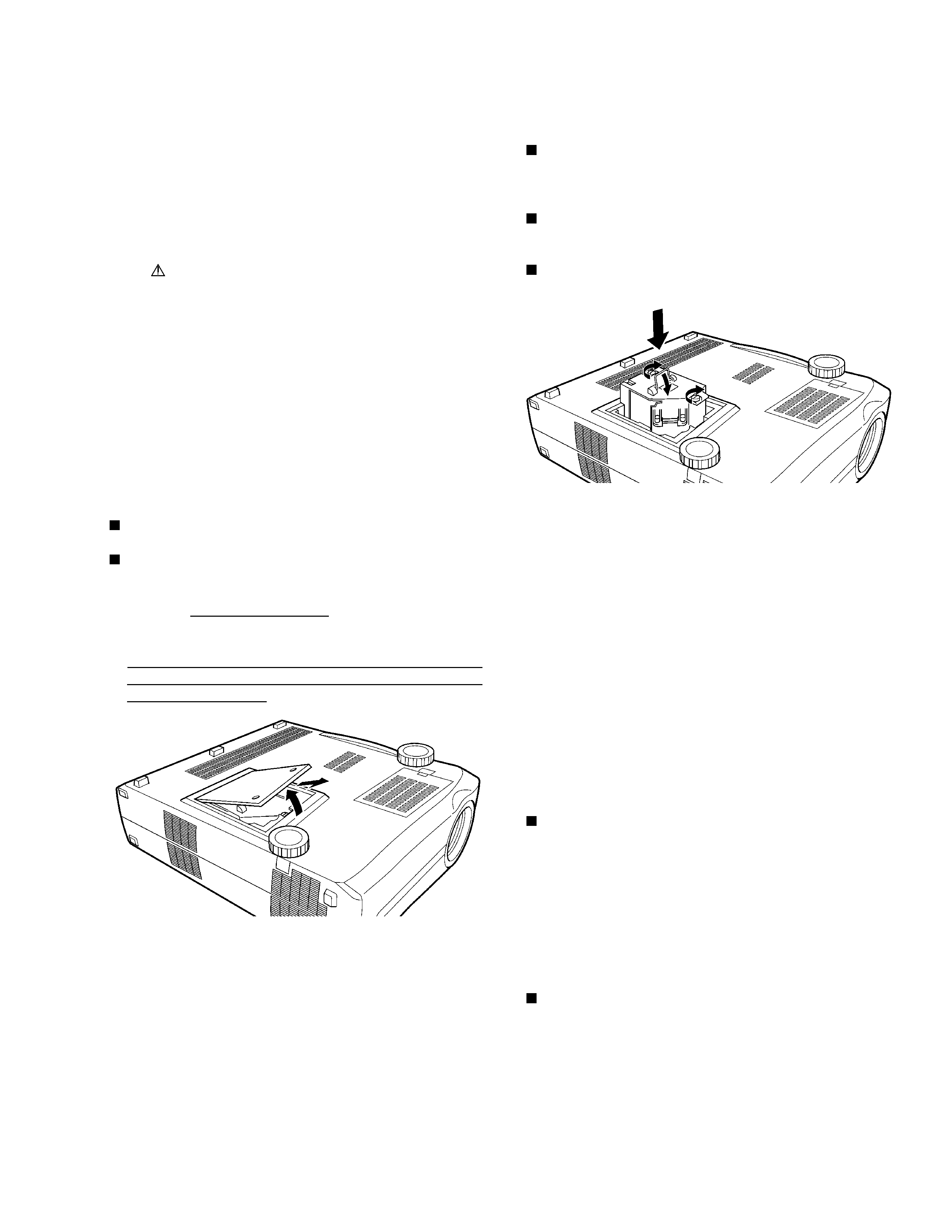
1.3 REPLACING THE LAMP
The system sets the interlock switch to OFF when the cover is
removed. For safety reasons, the power cannot be turned ON.
Be sure to disconnect the power plug when replacing the lamp.
The projector will still be very hot inside just after the power is
turned off.
Therefore, wait more than one hour after turning off the power
and check that the projector has cooled down inside before
replacing the lamp.
Replacing the lamp while the projector is being used or
immediately after it has been stopped will cause burns because
the lamp is still very hot.
1.4 CAUTION: HIGH TEMPERATURE
The mirror case and lamp assembly of this system become hot during
operation. Before servicing, turn the power off and wait until the
system cools down.
1.5 CHARGED SECTION
Charged section
The circuit in which the commercial AC power is used as it is without
passing through the power supply transformer. If the charged section
is touched, there is a risk of electric shock. In addition, the measuring
equipment can be damaged if it is connected to the GND of the
charged section and the GND of the non-charged section while
connecting the set directly to the commercial AC power supply. In
this case, be sure to connect the set via an insulated transformer and
supply the current.
Charged section (Power supply primary side)
1. AC FILTER Assy
2. The primary side of the DC POWER SUPPLY Assy
3. AC INLET
4. Power Switch (S2303)
5. AC Power Cord
6. Interlock Switch (S2301)
7. Thermostat (S2302)
Push down the handle in
the direction shown.
Never touch the light bulb or the reflecting mirror with your bare
hands. Dirt left behind from fingerprints or from your hands could
cause the lamp to overheat, and this in turn could shorten the
effective life of the lamp.
Be sure to read the instruction manual provided with your Liquid
crystal projector before replacing the lamp. (Also be sure to reset
to the lamp life meter after replacing the lamp.)
Push down the handle in the direction shown.
4
RVD-XG10, RVD-XG10ED, RVA-VK10
2. EXPLODED VIEWS AND PARTS LIST
NOTES:
· Parts marked by "NSP" are generally unavailable because they are not in our Master Spare Parts List.
· The mark found on some component parts indicates the importance of the safety factor of the part.
Therefore, when replacing, be sure to use parts of identical designation.
· Screws adjacent to mark on the product are used for disassembly.
CO
M
PU
TE
R
M
AC
XG
A
M
O
NIT
O
R
M
AC
O
UT
23
18
24
21
22
22
20
1
2
13
12
16
29
Lens Cap
19
28
15
14
27
4
26
25
10
3
17
RVD-XG10ED Only
RVD-XG10 Only
11
RVD-XG10 Only
9
7
5
6
8
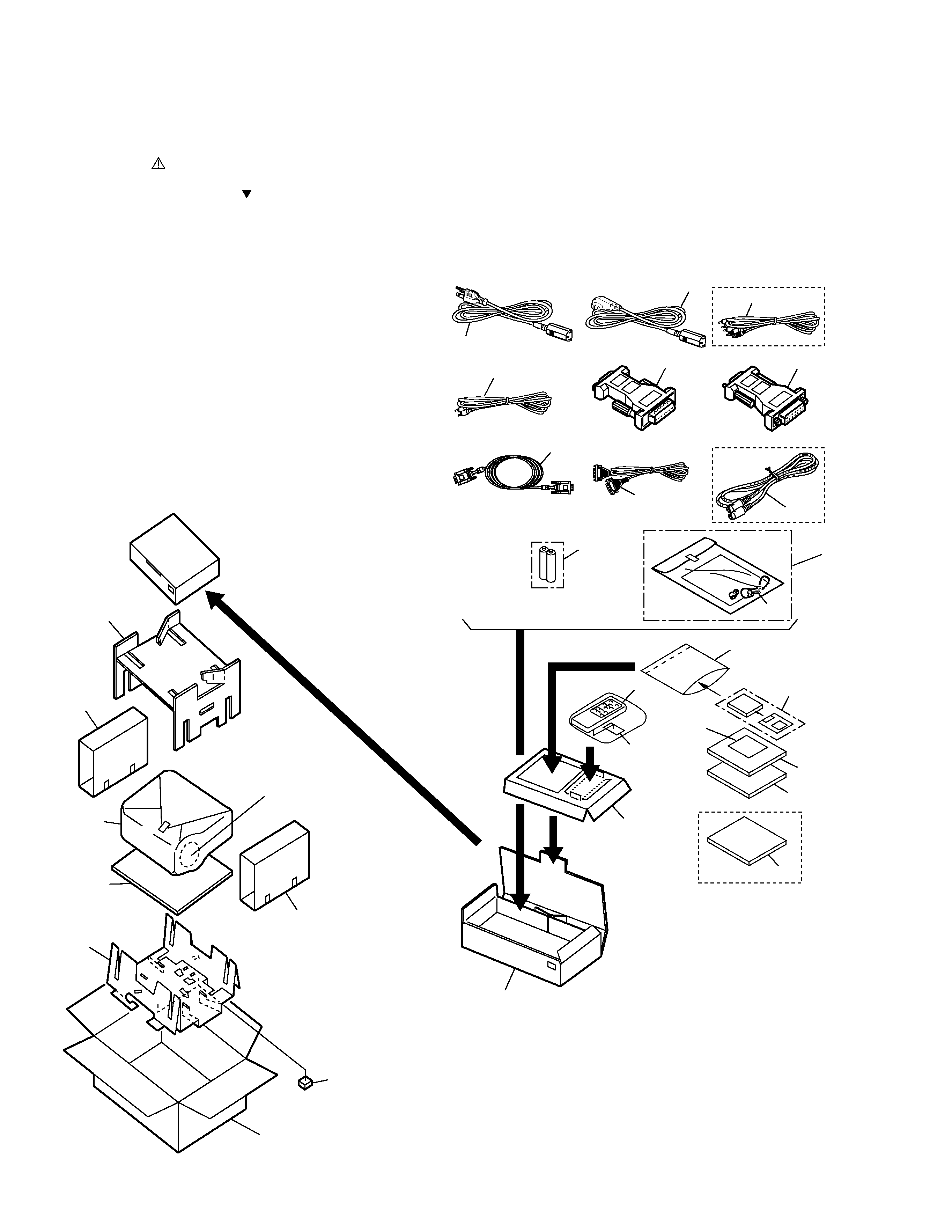
2.1 PACKING FOR RVD-XG10 AND RVD-XG10ED
5
RVD-XG10, RVD-XG10ED, RVA-VK10
1
ACCESSORY CASE
AHC9004
2
ACCESSORY PAD
AHC9005
3
CORD FOR CONNECTING
ADE9016
COMPUTER
4
LENS CAP SET
AEA9002
(HOLDER + SCREW + STRING)
5
POWER CORD
ADG9008
6
POWER CORD
ADG9009
7
STEREO MINI PLUG CORD
ADE9023
8
AV CORD
See Contrast table (2)
9
CONVERSION ADAPTER
ADE9009
(FOR MACINTOSH INPUT)
10
CONVERSION ADAPTER
ADE9010
(FOR MACINTOSH OUTPUT)
NSP
11
DRY CELL BATTERY (R6P,AA) AEX-010
12
REMOTE CONTROL UNIT
AXD9004
(CU-V156)
13
BATTERY COVER
AZN9010
14
OPERATING INSTRUCTIONS ARE9003
(ENGLISH / FRENCH)
15
OPERATING INSTRUCTIONS ARC9007
(SPANISH)
NSP
16
VINYL BAG
AHG1083
17
SCREW
PMB40P200FZK
18
PACKING CASE
See Contrast table (2)
19
PACKING SHEET
AHG1172
20
PAD (UPPER)
AHA9006
21
PAD (UNDER)
AHA9007
22
PAD (SIDE)
AHB9005
23
SPACER
AHB9006
24
SUB PAD
AHB9007
25
RS-232C CABLE
ADE9017
26
S-VIDEO CORD
See Contrast table (2)
27
FLOPPY DISK
AWX9002
28
OPERATING INSTRUCTIONS See Contrast table (2)
(GERMAN/ITALIAN)
NSP
29
FD CAUTION
ARM9006
(2) CONTRAST TABLE
RVD-XG10/TUCYL and RVD-XG10ED/TUCYL have the same construction except for the following :
Mark
No.
Symbol and Description
RVD-XG10/TUCYL
RVD-XG10ED/TUCYL
Remarks
Part No.
8
AV CORD
ADE9022
Not used
18
PACKING CASE
AHD9019
AHD9018
26
S-VIDEO CORD
ADE9021
Not used
28
OPERATING INSTRUCTIONS
Not used
ARC9006
(GERMAN / ITALIAN)
(1) PACKING FOR RVD-XG10 AND RVD-XG10ED PARTS LIST
Mark No.
Description
Part No.