ORDER NO.
PIONEER ELECTRONIC CORPORATION 4-1, Meguro 1-Chome, Meguro-ku, Tokyo 153-8654, Japan
PIONEER ELECTRONICS SERVICE, INC. P.O. Box 1760, Long Beach, CA 90801-1760, U.S.A.
PIONEER ELECTRONIC (EUROPE) N.V. Haven 1087, Keetberglaan 1, 9120 Melsele, Belgium
PIONEER ELECTRONICS ASIACENTRE PTE. LTD. 253 Alexandra Road, #04-01, Singapore 159936
PIONEER ELECTRONIC CORPORATION 1999
RRV2125
T ZZY APR. 1999 Printed in Japan
RF DEMODULATOR
RFD-1
CONTENTS
1. SAFETY INFORMATION ..................................... 2
2. EXPLODED VIEWS AND PARTS LIST ............... 3
3. BLOCK DIAGRAM AND SCHEMATIC DIAGRAM 6
4. PCB CONNECTION DIAGRAM ......................... 10
5. PCB PARTS LIST .............................................. 13
6. ADJUSTMENT ................................................... 14
7. PANEL FACILITIES AND SPECIFICATIONS ..... 14
THIS MANUAL IS APPLICABLE TO THE FOLLOWING MODEL(S) AND TYPE(S).
Type
Model
RFD-1
Power Requirement
MY
O
AC220 - 230V
Remarks
2
RFD-1
1. SAFETY INFORMATION
This service manual is intended for qualified service technicians ; it is not meant for the casual do-it-
yourselfer. Qualified technicians have the necessary test equipment and tools, and have been trained
to properly and safely repair complex products such as those covered by this manual.
Improperly performed repairs can adversely affect the safety and reliability of the product and may
void the warranty. If you are not qualified to perform the repair of this product properly and safely, you
should not risk trying to do so and refer the repair to a qualified service technician.
WARNING
Lead in solder used in this product is listed by the California Health and Welfare agency as a known reproductive toxicant which may
cause birth defects or other reproductive harm (California Health & Safety Code, Section 25249.5).
When servicing or handling circuit boards and other components which contain lead in solder, avoid unprotected skin contact with
the solder. Also, when soldering do not inhale any smoke or fumes produced.
NOTICE
(FOR CANADIAN MODEL ONLY)
Fuse symbols
(fast operating fuse) and/or
(slow operating fuse) on PCB indicate that replacement parts must
be of identical designation.
REMARQUE
(POUR MODÈLE CANADIEN SEULEMENT)
Les symboles de fusible
(fusible de type rapide) et/ou
(fusible de type lent) sur CCI indiquent que les pièces
de remplacement doivent avoir la même désignation.
ANY MEASUREMENTS NOT WITHIN THE LIMITS
OUTLINED ABOVE ARE INDICATIVE OF A POTENTIAL
SHOCK HAZARD AND MUST BE CORRECTED BEFORE
RETURNING THE APPLIANCE TO THE CUSTOMER.
2. PRODUCT SAFETY NOTICE
Many electrical and mechanical parts in the appliance
have special safety related characteristics. These are
often not evident from visual inspection nor the protection
afforded by them necessarily can be obtained by using
replacement components rated for voltage, wattage, etc.
Replacement parts which have these special safety
characteristics are identified in this Service Manual.
Electrical components having such features are identified
by marking with a
on the schematics and on the parts list
in this Service Manual.
The use of a substitute replacement component which does
not have the same safety characteristics as the PIONEER
recommended replacement one, shown in the parts list in
this Service Manual, may create shock, fire, or other hazards.
Product Safety is continuously under review and new
instructions are issued from time to time. For the latest
information, always consult the current PIONEER Service
Manual. A subscription to, or additional copies of, PIONEER
Service Manual may be obtained at a nominal charge from
PIONEER.
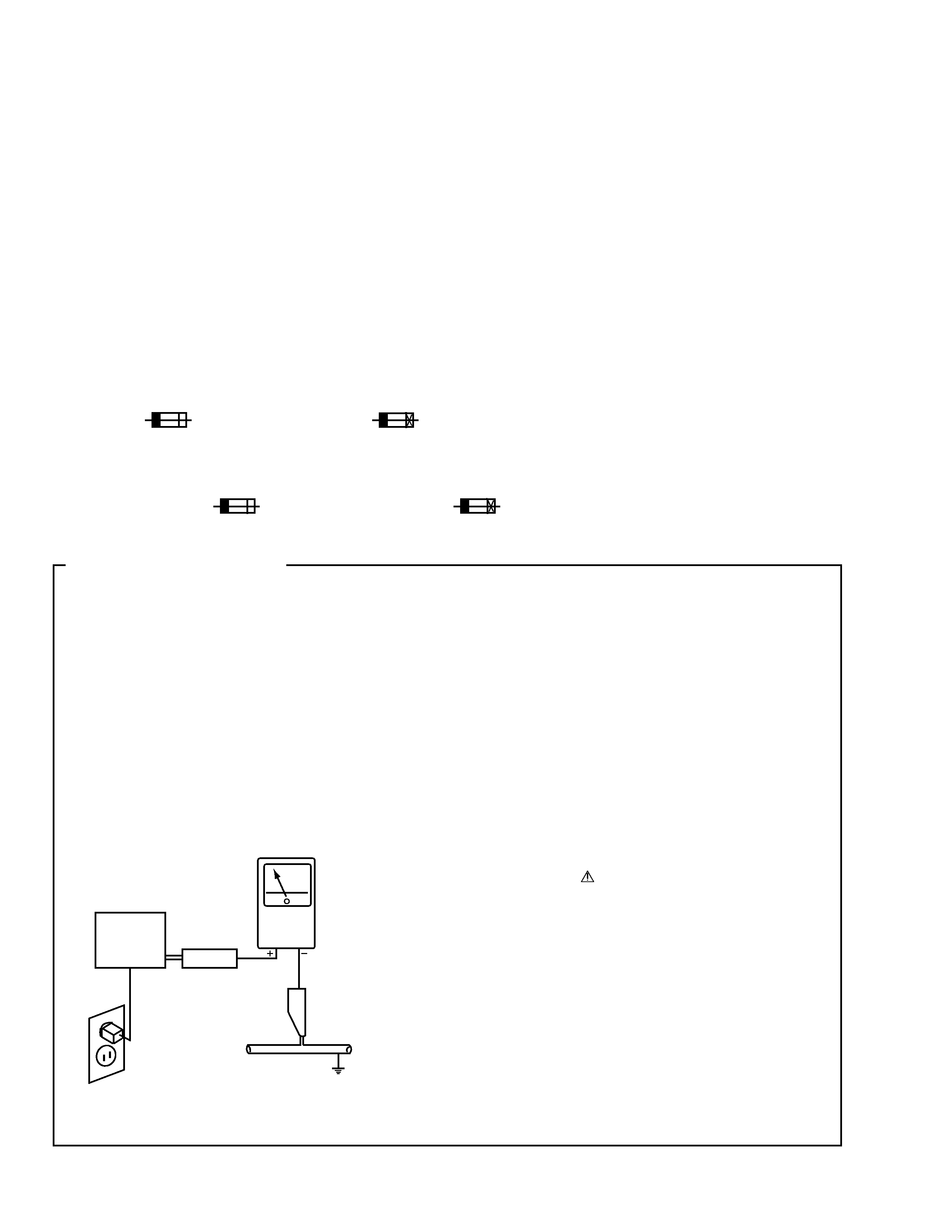
1. SAFETY PRECAUTIONS
The following check should be performed for the
continued protection of the customer and service
technician.
LEAKAGE CURRENT CHECK
Measure leakage current to a known earth ground (water
pipe, conduit, etc.) by connecting a leakage current tester
such as Simpson Model 229-2 or equivalent between the
earth ground and all exposed metal parts of the appliance
(input/output terminals, screwheads, metal overlays, control
shaft, etc.). Plug the AC line cord of the appliance directly
into a 120V AC 60Hz outlet and turn the AC power switch
on. Any current measured must not exceed 0.5mA.
(FOR USA MODEL ONLY)
Leakage
current
tester
Reading should
not be above
0.5mA
Device
under
test
Test all
exposed metal
surfaces
Also test with
plug reversed
(Using AC adapter
plug as required)
Earth
ground
AC Leakage Test
3
RFD-1
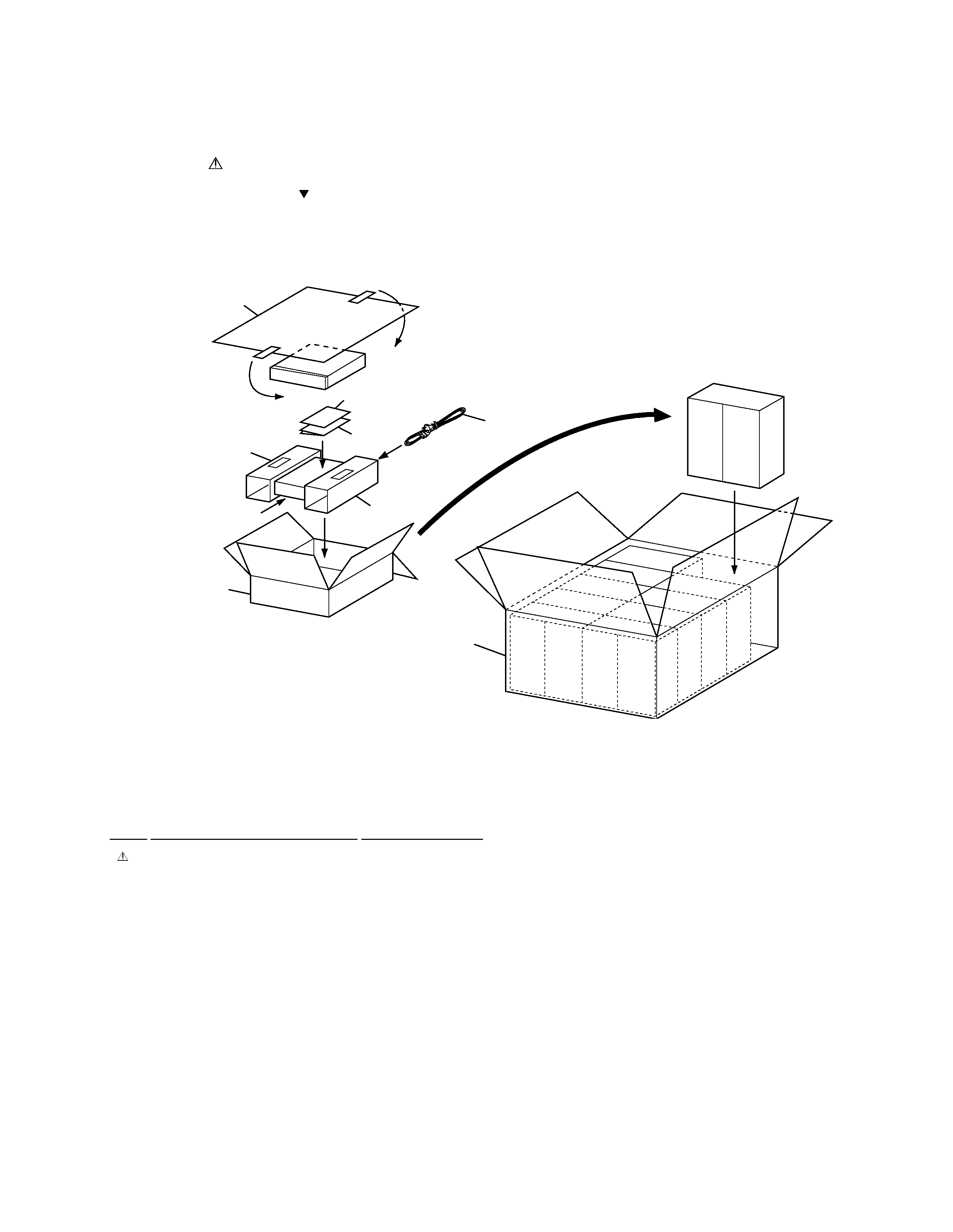
2.1 PACKING
1
Power Cord
ADG1127
NSP
2
Warranty Card
ARY7022
3
Operating Instructions
ARE7212
(English/French/German/Italian
/Dutch/Swedish/Spanish/Portuguese)
4
Protector
DHA1235
5
Packing Sheet
RHC1050
6
Packing Case
AHG7058
7
Master Carton
AHG7060
PACKING PARTS LIST
Mark No.
Description
Part No.
2. EXPLODED VIEWS and PARTS LIST
NOTES:
· Parts marked by "NSP" are generally unavailable because they are not in our Master Spare Parts List.
· The mark found on some component parts indicates the importance of the safety factor of the part.
Therefore, when replacing, be sure to use parts of identical designation.
· Screws adjacent to mark on the product are used for disassembly.
FRONT
FRONT
PIONEER
PIONEER
PIONEER
PIONEER
PIONEER
5
2
3
1
4
6
7
4
4
RFD-1
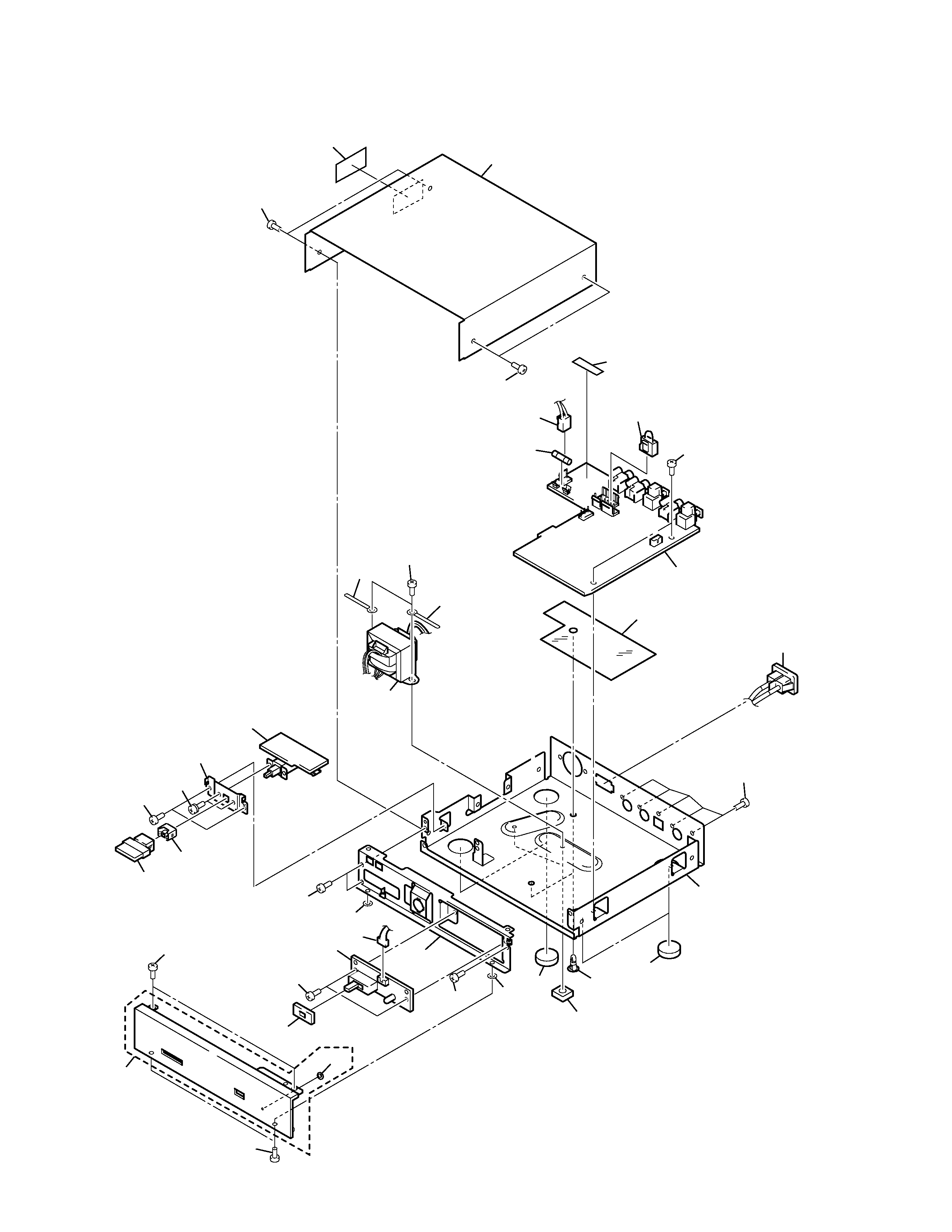
2.2 EXTERIOR
23
26
17
26
32
5
4
8
27
2
16
7
27
18
15
11
12
15
14
14
3
6
26
26
26
33
26
26
20
13
26
28
19
1
22
21
10
26
29
29
9

5
RFD-1
(1) EXTERIOR PARTS LIST
Mark No.
Description
Part No.
1
SW Assy
VWR1303
2
DEM Assy
VWV1601
NSP
3
LED Assy
VWY1048
4
Fuse (FU1: T250mA)
AEK1048
5
Housing Assy (3P)
VKP2178
6
Housing Assy (4P)
VKP2179
7
AC Inlet Assy
VKP2183
8
Housing Assy (7P)
AKP7037
9
Power Transformer
VTT1153
(AC220-230V)
NSP
10
Front Stay
DND1140
11
Locking Card Spacer
ONK1035
12
Disc Guard
PNM1245
13
Guide Ring
VEC-151
14
Washer
VEC1254
15
Poron Leg
VEC1987
16
Sheet B (PVC)
VEC1990
17
Bonnet Case
VNA1952
NSP
18
Main Chassis
ANA7084
19
SW Stay
VNE2148
20
Power Knob
VAC1030
21
Cushion
AEC7225
22
Front Panel Assy
AXA7072
23
Caution Label
ARW7036
24
········
25
········
26
Screw
BBZ30P060FZK
27
Screw
BBZ30P080FCC
28
Screw
PMA30P060FMC
NSP
29
Cord Stopper
ZCB-069Z
30
········
31
········
32
Fuse Label
VRW1727
33
LED Lens
DNK2331
Mark No.
Description
Part No.